Advertisement
Table of Contents
- 1 Table of Contents
- 2 Preventing Static Electricity
- 3 Important for Laser Products
- 4 Disassembly Method
- 5 Flow of Functional Operation until
- 6 TOC Read (MD)
- 7 Maintenance of Laser Pickup (CD)
- 8 Maintenance of Laser Pickup(MD)
- 9 Description of Major Ics 1-41~68
- Download this manual
See also:
Instruction Manual
SERVICE MANUAL
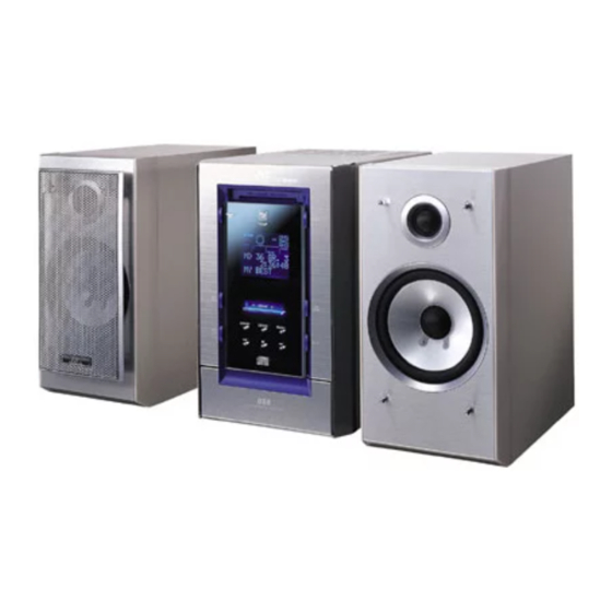
COMPACT COMPONENT MD SYSTEM
SP-NXMD1
Contents
Safety precautions
Adjustment method
(CD/MD section)
Flow of functional operation until
TOC read (CD)
CA-NXMD1R/CA-NXMD1 SP-NXMD1
1-2
1-3
1-5
1-6
1-32
1-37
COPYRIGHT
2001 VICTOR COMPANY OF JAPAN, LTD.
Replacement of laser pickup (CD)
Replacement of laser pickup(MD)
NX-MD1R/NX-MD1
Area suffix [NX-MD1R]
B ------------------------------ U.K.
E ---------- Continental Europe
EN ----------- Northern Europe
Area suffix [NX-MD1]
A ------------------------ Australia
US -------------------- Singapore
UB ------------------- Hong Kong
UP -------------------------- Korea
1-38
1-39
1-39
1-40
1-40
1-41~68
No.21041
Oct. 2001
Advertisement
Table of Contents

Subscribe to Our Youtube Channel
Related Manuals for JVC NX-MD1R


Summary of Contents for JVC NX-MD1R
-
Page 1: Table Of Contents
NX-MD1R/NX-MD1 SERVICE MANUAL COMPACT COMPONENT MD SYSTEM NX-MD1R / NX-MD1 Area suffix [NX-MD1R] B ------------------------------ U.K. E ---------- Continental Europe EN ----------- Northern Europe Area suffix [NX-MD1] A ------------------------ Australia US -------------------- Singapore UB ------------------- Hong Kong UP -------------------------- Korea... - Page 2 NX-MD1R/NX-MD1 1. This design of this product contains special hardware and many circuits and components specially for safety purposes. For continued protection, no changes should be made to the original design unless authorized in writing by the manufacturer. Replacement parts must be identical to those used in the original circuits. Services should be performed by qualified personnel only.
-
Page 3: Preventing Static Electricity
NX-MD1R/NX-MD1 Preventing static electricity 1. Grounding to prevent damage by static electricity Electrostatic discharge (ESD), which occurs when static electricity stored in the body, fabric, etc. is discharged, can destroy the laser diode in the traverse unit (optical pickup). Take care to prevent this when performing repairs. - Page 4 NX-MD1R/NX-MD1 5. Attention when MD traverse unit is decomposed *Please refer to "Disassembly method" in the text for pick-up and how to detach the substrate. *Please refer to "Disassembly method" in the text for pick-up and how to detach the substrate.
-
Page 5: Important For Laser Products
NX-MD1R/NX-MD1 Important for laser products 5.CAUTION : If safety switches malfunction, the laser is able 1.CLASS 1 LASER PRODUCT to function. 2.DANGER : Invisible laser radiation when open and inter 6.CAUTION : Use of controls, adjustments or performance of lock failed or defeated. Avoid direct exposure to beam. -
Page 6: Disassembly Method
NX-MD1R/NX-MD1 Disassembly method Top cover <Main body section> Removing the top cover (See Fig.1 and 2) Remove the four screws A attaching the top cover from the back side of the main body. Remove the two screws B attaching the top cover from the both sides of the main body. - Page 7 NX-MD1R/NX-MD1 Removing the system control board CN605 Card wire support board (See Fig.4) CN602 CN603 Prior to performing the following procedure, remove the top cover. Prior to performing the following procedure, remove the rear cover. Remove the screw D attaching the card wire support board, then remove the card wire support board.
- Page 8 NX-MD1R/NX-MD1 Removing the regulator board (See Fig.7) Prior to performing the following procedure, remove the top cover. Prior to performing the following procedure, remove the rear cover. CN995 Prior to performing the following procedure, remove CN903 the system control board.
- Page 9 NX-MD1R/NX-MD1 Removing the MD mechanism assembly (See Fig.9) Prior to performing the following procedure, remove the top cover. Prior to performing the following procedure, remove the rear cover. Earth wire Prior to performing the following procedure, remove the system control board.
- Page 10 NX-MD1R/NX-MD1 Removing the power board (See Fig.12) Prior to performing the following procedure, remove the top cover. Prior to performing the following procedure, remove the rear cover. Prior to performing the following procedure, remove the system control board. Prior to performing the following procedure, remove the main amplifier board.
- Page 11 NX-MD1R/NX-MD1 Removing the CD mechanism assembly (See Fig.13 and 14) Prior to performing the following procedure, remove the top cover. Prior to performing the following procedure, remove the rear cover. Fun motor assembly Prior to performing the following procedure, remove the system control board.
- Page 12 NX-MD1R/NX-MD1 Removing the front panel assembly (See Fig.15) Prior to performing the following procedure, remove the top cover. Front panel assembly Bottom chassis Prior to performing the following procedure, remove Claw f the rear cover. Prior to performing the following procedure, remove the system control board.
- Page 13 NX-MD1R/NX-MD1 <Front panel assembly section> Prior to performing the following procedure, remove the front panel assembly. MD bracket Location hole g Removing the front board (See Fig.16) Location hole g Remove the two screws Y attaching the MD Front board bracket.
- Page 14 NX-MD1R/NX-MD1 <MD mechanism assembly section> Prior to performing the following procedure, remove the top cover. Prior to performing the following procedure, remove Earth plate board the rear cover. Prior to performing the following procedure, remove Card wire the MD mechanism assembly.
-
Page 15: Nx-Md1R/Nx-Md1
NX-MD1R/NX-MD1 <Speaker section> Joints a Note : Avoid replacing individual parts. Removing the front cover (See Fig.1 to 3) Pull out the saran net toward the front while disengaging the four joints a. Insert the tip of a flat-bladed screwdriver or a similar tool into the joints b between the main body and the front cover from the bottom of the main body. - Page 16 NX-MD1R/NX-MD1 Removing the woofer speaker (See Fig.4) Prior to performing the following procedure, remove the front cover. Remove the four screws A on the front of the body. Pull out the woofer speaker toward the front and disconnect the wire (yellow and black,blue and black) from the two speaker terminals.
- Page 17 NX-MD1R/NX-MD1 CL. base assembly <CD Mechanism Assembly> Hook a Removing the CL. Base Assembly and Hook a Tray (Refer to Figs. 1 to 5.) 1. Remove the two screws A fastening the CL. base assembly from the top of the CD mechanism assembly.
- Page 18 NX-MD1R/NX-MD1 Removing the TRAMECHA Assembly (Refer to Figs. 6 to 9.) Remove the CL. base assembly and tray. Reference: The TRAMECHA assembly can be Idle gear removed without removal of the mechanism P.C. board. TRAMECHA 1. If the TRAMECHA assembly is lowered and it is...
- Page 19 NX-MD1R/NX-MD1 Removing the Mechanism P.C. Board (Refer to Fig 10.) Flexible wire Reference:The mechanism P.C. board can be removed without removal of the TRAMECHA assembly. Shorting round Note: Before disconnecting the flexible wire coming CN601 on Soldered from the pickup from the connector, be sure to...
- Page 20 NX-MD1R/NX-MD1 Flexible wire Removing the Pickup (Refer to Figs. 11 to 14.) Shorting round Remove the CL. base assembly and tray. Remove the TRAMECHA assembly. Reference: The pickup can be removed without CN601 on removal of the mechanism P.C. board.
- Page 21 NX-MD1R/NX-MD1 Reinstalling the Pickup Assembly Part k (Refer to Figs. 15 and 16.) Part j Reference: Refer to the explanation of "Removing the Pickup" on the preceding page. Pickup assembly 1. Fit the P.S. spring and rack plate to the pickup.
- Page 22 NX-MD1R/NX-MD1 <MD mechanism section> Removing the MD servo board (See Fig.1 and 2) CN521 Turn over the body and disconnect the card wires MD servo board from connectors CN408, CN521 and the flexible wire from CN407 on the MD servo board.
- Page 23 NX-MD1R/NX-MD1 Removing the head lifter (See Fig.4 to 6) Move the head lifter on top of the body in the Head lifter direction of the arrow and turn around. Detach the spring from the hook of the body. Remove the head lifter with the spring.
- Page 24 NX-MD1R/NX-MD1 Removing the Loading assembly (See Fig.8 and 9) Ref: The loading assembly, the traverse mechanism assembly and the single flame will be removable after removing the loading assembly from the body. Loading assembly Prior to performing the following procedure, remove the MD servo board, the mechanism cover, the head lifter and the head assembly.
- Page 25 NX-MD1R/NX-MD1 <Loading assembly section> Slide base (R) Boss e' Removing the slide base (L) / (R) (See Fig.10) Remove the two screws E on the top side of the loading assembly. Remove the slide base (L) outward. (Release it from the joint bosses e'.)
- Page 26 NX-MD1R/NX-MD1 Removing the cartridge holder assembly (See Fig.14 and 15) Remove the two screws J on the top side of the Slide bar loading assembly. Cartridge holder assembly Eject bar Eject bar Part g Removing the slide bar and the eject bar Fig.14...
- Page 27 NX-MD1R/NX-MD1 <Traverse mechanism assembly section> Insulators Removing the Insulators (See Fig.16) Pickup unit Disengage the four insulators from the notches of the traverse mechanism chassis. Insulators Traverse machanism chassis Fig.16 Joint h Pickup guide Removing the pickup unit (See Fig.17) Turn over the traverse mechanism assembly and remove the screw K attaching the shaft holder (F).
- Page 28 NX-MD1R/NX-MD1 Removing the feed motor assembly (See Fig.19, 20) Traberse mechanism board Soldering j It is not necessary to remove the pickup unit. For the white and black harnesses extending from the feed motor assembly, unsolder the soldering i on the traverse mechanism board.
- Page 29 NX-MD1R/NX-MD1 <Reattaching the loading assembly> Reattach the eject bar to the UD base. (Fig.15 and 21) Reattach the slide bar to the loading mechanism chassis while fitting the boss marked k to the eject bar ditch k'. (Fig.21) Slide the slide bar and the eject bar in the direction of the arrow in Fig.21 and reattach the cartridge...
- Page 30 NX-MD1R/NX-MD1 Reattach the wire holder to the UD base while engaging the UD base hook marked r to the wire holder slot marked q (At the same time, the boss on the reverse side of the wire holder is fitted to the UD base round hole).
- Page 31 NX-MD1R/NX-MD1 Reattach the UD base while engaging the four pins on both sides of the UD base to the notches of the loading mechanism base and placing the edge (marked e") of the cartridge holder assembly under the hook e of the loading mechanism base. (Fig.24) Hook e"...
- Page 32 NX-MD1R/NX-MD1 Adjustment Method (CD/MD section) 1. Jigs and test instruments Laser power meter Laser power meter sensor (or disk sensor) Premastered disk (MRG-1018 or TGYS1) Recordable disk (MDW-74/AU1) 2. CD check method Remove the four screws retaining the top cover from the rear panel and the two screws retaining it from the left and right side panels.
- Page 33 NX-MD1R/NX-MD1 4. Adjustment and check items 1) CD section (1) Indication of the C1 error (2) Cancel of the C1 error indication 2) MD section (1) Setup of the TEST MODE 1 (2) Initialization of the EEPROM (3) Adjustment of the laser power...
- Page 34 NX-MD1R/NX-MD1 2) MD section (2) Initialization of the EEPROM (1) Setup of the TEST MODE 1 (The EEPROM can be initialized on the precondition that the While pressing both the STOP setup of the TEST MODE 1 is complete. After setup of the...
- Page 35 NX-MD1R/NX-MD1 (4) Adjustment of the disk Insert the premastered disk. Reading of TOC ends. Press the MD PLAY key on the remote controller. FL indication ON TUNING Automatic adjustment starts. Adjustment OK? FL indication FL indication XX: Refer to the NG judgment code table.
- Page 36 NX-MD1R/NX-MD1 For investigating the mode in which an error Key to press Mode occurred during the disk adjustment, freeze the SLEEP key (Remote controller) FOCUS SEARCH set in the mode by pressing the proper key "6" key (Remote controller) PIT ROUGH SERVO (refer to the table on the right) on the remote "7"...
-
Page 37: Flow Of Functional Operation Until
NX-MD1R/NX-MD1 Flow of functional operation until TOC read (CD) Check Point Slider turns REST Play Key Power ON Confirm that the voltage at the pin32 SW ON. of IC251 is "H"\"L"\"H". Automatic tuning of TE offset Laser ON Detection of disc... - Page 38 NX-MD1R/NX-MD1 Flow of functional operation until TOC read (MD) Power ON MD play key Check Point Slider turns REST Confirm that the voltage Switch ON. at the pin 9 of CN408 are 0V Mechanism Operation ON Confirm that the voltage...
-
Page 39: Maintenance Of Laser Pickup (Cd)
NX-MD1R/NX-MD1 Maintenance of laser pickup (CD) Replacement of laser pickup (CD) (1) Cleaning the pick up lens Before you replace the pick up, please try to Turn off the power switch and,disconnect the clean the lens with a alcohol soaked cotton power cord from the AC OUTLET. -
Page 40: Maintenance Of Laser Pickup(Md)
NX-MD1R/NX-MD1 Maintenance of laser pickup (MD) Replacement of laser pickup (MD) 1. Cleaning of pickup lens Change the MD pickup by referring Prior to changing the pickup, clean the pickup lens. to "Removing the MD pickup" in the Disassembly Method. -
Page 41: Description Of Major Ics 1-41~68
NX-MD1R/NX-MD1 Description of major ICs AK4519VF (IC480) : A/D, D/A converter 1.Terminal layout 2.Block diagram VA AGND VB VD DGND AINL Decimation Clock MCLK Modulator VCML Filter Divider CMODE AINR LRCK Decimation Modulator VCMR SCLK Filter VRAD Serial I/O SDTO... - Page 42 NX-MD1R/NX-MD1 AN22000A(IC601):RF & SERVO AMP 1. Terminal layout 2. Block diagram OFTR RF IN C.AGC CBDO COFTR RF OUT OFTR RF_EQ 3TENV NRFDET 3TOUT NRFDET SUBT FEOUT SUBT TEOUT TEBPF VDET VDET VREF GCTL TBAL FBAL CDDG VCC 3. Pin function...
- Page 43 NX-MD1R/NX-MD1 BD7910FV (IC450) : Pre driver 1.Block diagram Mute Pre driver SVcc Vregin 2.Pin function Symbol Function Symbol Function Vreg IN Regulator input and regulator Non connect power supply VOD2 Sync.output (Lower power MOS,drain) Reg GN Regulator GND "H"bridge GND (Lower power MOS,source)
- Page 44 NX-MD1R/NX-MD1 BR93LC66F (IC590) : 256 x 16 bit serial EEPROM 1. Terminal layout 2. Block diagram Power supply voltage detector Command code Control High voltage Write disable generator Clock generation Address Address 8bits Command 8bits buffer decoder register 4096bits EEPROM array...
- Page 45 NX-MD1R/NX-MD1 GP1U271X (IC721) : Receiver for remote 1. Block diagram – Limiter Comparator Amp. Integrator Demodulator B.P.F DATA TC7S08F (IC340) : Buffer 1. Terminal layout 2. Block diagram IN B IN A OUT X TK11140SC (IC485) : Regulator 1.Terminal layout 2.Block diagram...
- Page 46 NX-MD1R/NX-MD1 CXA2523AR (IC310) : MD servo 1.Block diagram ADIP Amp TE/SE Amp PEAK 3TADJ FE Amp RFAGC 22 EQADJ AGCI 21 VREF COMPO 20 F0CNT COMPP 19 XSTBY ADDC 18 XLAT 17 SCLK Command I/F 16 SWDT 15 TEMP R...
- Page 47 NX-MD1R/NX-MD1 Symbol Function Pin No. Reference voltage output. VREF Equalizer center frequency setting pin. EQADJ BPF3T center frequency setting pin. 3TADJ Power supply. BPF22 center frequency setting pin. WBLADJ Tracking error signal output. Connects the sled error signal LPF capacitor.
- Page 48 NX-MD1R/NX-MD1 CXD2662R (IC350) : DSP 1.Terminal layout 2.Block diagram 16 17 18 29 27 28 90 52 CLOCK FILI XRAS GENERATOR FILO XCAS CLTV EFM / ACIRC each block ENCODER / DECODER A00~A11 COMP D0~D3 XINT SHOCK RESISTANT ASYI MEMORY CONTROLLER...
- Page 49 NX-MD1R/NX-MD1 3.Pin function Symbol Function Pin No. MNT0 Monitor output. MNT1 Monitor output. MNT2 Monitor output. MNT3 Monitor output. SWDT Data input for microcomputer serial interface. SCLK Shift clook input for microcomputer serial interface. XLAT Latch input for microcomputer serial interface.Latched at the falling edge.
- Page 50 NX-MD1R/NX-MD1 Symbol Function Pin No. XCAS External DRAM CAS output. External DRAM address output. XRAS External DRAM RAS output. External DRAM write enable. External DRAM data bus. External DRAM data bus. External DRAM data bus. External DRAM data bus. MDDTI MD-DATA mode 1 switching input.
- Page 51 NX-MD1R/NX-MD1 Symbol Function Pin No. SRDR Sled servo drive PWM output. ( ) SFDR Sled servo drive PWM output. (+) SPRD Spindle servo drive output. (PWM ( ) or polarity) SPFD Spindle servo drive output. (PWM (+) or PWM absolute value) FGIN Spindle CAV servo FG input.
- Page 52 NX-MD1R/NX-MD1 LA1838 (IC1): FM AM IF AMP&detector, FM MPX decoder 1. Block Diagram DECODER RF.AMP ANIT-BIRDIE MUTE BUFF STEREO P-DET AM IF PILOT 384KHz COMP S-METER AM/FM S-CLRVE S-METER IF-BUFF TUNING STEREO DRIVE DRIVE FM IF 2. Pin Function Symbol...
- Page 53 NX-MD1R/NX-MD1 LA4628 (IC301) : 2ch BTL AF power amplifier 1. Terminal layout 2. Block diagram VCC short protector Ripple output pin fillter -OUTR Pre driver Power POWER Load short GND1 protector +OUTR Pre driver Power GND short protector Bias Over voltage...
- Page 54 NX-MD1R/NX-MD1 LA6541 (IC801) : Servo driver 1. Terminal Layout & block diagram Vref Vin4 Vin3 Level B T L B T L Level RESET shift driver driver shift Level B T L B T L Level Regulator shift driver driver...
- Page 55 NX-MD1R/NX-MD1 LC72136N (IC2) : PLL frequency synthesizer 1. Terminal layout FM/AM LPFOUT LPFIN CLOCK FM/ST/VCO FMIN AM/FM AMIN IFCONT SDIN IFIN 2. Block diagram Phase Reference Detector Driver Charge Pump Swallow Counter Swallow Counter 1/16,1/17 4bit 1/16,1/17 4bit Unlock Detector...
- Page 56 NX-MD1R/NX-MD1 LC75345M (IC302) : Electric volume 2. Pin functin 1. Terminal layout Pin No. Symbol Function VOLDI Serial data pins and clock input pin for control VOLCE Chip enable VOLDI VOLCL Connect to GND VOLCE LOPOUT General-purpose op-amp output pin (Lch)
- Page 57 NX-MD1R/NX-MD1 MIIL1644SA-50T (IC390) : DRAM 2. Pin function 1. Terminal layout Function Pin No. Symbol Power supply(3.3V) 1.13 DO~D3 Data I/O 2.3.24.25 Write enable load adress strobe AO~A11 Adress input 6.8~12. (4K Refresh Product) 15~19.21 AO~A10 Adress input 8~12. (2K Refresh Product) 15~19.21...
- Page 58 NX-MD1R/NX-MD1 M63008FP (IC410) : 5ch Actuator driver 1.Terminal layout 2.Block diagram VBS1 VBS2 VBS2 IN3- VBS1 IN3+ IN1+ OUT3 IN1- CH3 IN OUT1 VBS1 VBS2 VM3(+) VM1(+) Vrefm1 Vrefm2 VM3(-) VM1(-) VBS1 VBS2 VM2(+) VM4(+) VM2(-) VREFO VM4(-) OUT2 HI :Sleep...
- Page 59 NX-MD1R/NX-MD1 PCM2702E (IC431) : D/A converter 1. Terminal layout 2. Block diagram Packet Audio Data Data Low-Pass OUTL Multi- Filter FIFO D– Level Over sampling Delta- wrclk Digital Filter Sigma Modulator Low-Pass DGNDU OUTR Filter mclk System Clock Audio Clock Clock SpAct™...
- Page 60 NX-MD1R/NX-MD1 MN101C49GJJ (IC801) : System micon 1. Terminal layout 100 ~ 76 26 ~ 50 2. Pin function Pin No. Symbol Function GND for A/D A/D GND KEY1 Front control switch input 1 Front control switch input 2 KEY2 Not use 6V/5.6V SAFETY DETECT...
- Page 61 NX-MD1R/NX-MD1 Pin No. Symbol Function CD 5V control FUNCTION CD MD control data I/O MD TX MD control data I/O MD RX Not use LCD data output LCD SDA LCD chip select output LCD CS LCD deta clock output LCD SCL...
- Page 62 NX-MD1R/NX-MD1 MN662790RSC (IC651) : Digital servo & digital signal prossesor 1.Terminal layout 2. Pin function No. Symbol Function No. Symbol Function BCLK Bit clock output for SRDATA PLLF2 LRCK LR signal separation output DSLBDA Not use SRDATA Serial data output...
- Page 63 NX-MD1R/NX-MD1 XC62HR3502P (IC291) : Regulator 1. Terminal layout 2. Block diagram Vout (NC) Vout Current limit Vss Vin ON/OFF Voltage Output control ON/OFF reference 3. Pin function Pin No. Symbol Function Power supply input ON/OFF ON/OFF control (NC) Not use...
- Page 64 NX-MD1R/NX-MD1 UPD780024AGKB21 (IC251) : Unit micon 1. Pin layout 2. Pin function (1/2) Symbol Function Connect to GND Non connect Synchronization/asynchronus system Reday signal input terminal MRDY CDINDEX CD emphasis CDEMP CD track No. change CDTNO CD copy right or wrong...
- Page 65 NX-MD1R/NX-MD1 2. Pin function (2/2) Symbol Function Connect to GND Referrence power supply voltage AVREF Power supply AVDD CD reset signal input /RESET Non connect Connect to power supply Not use (For flash micon) X'tal osc output X'tal osc input...
- Page 66 NX-MD1R/NX-MD1 UPD784217AGC139 (IC500) : MD control micon 1.Terminal layout 4XREC SVIB DINUNL MONICLK DRIVER_ON MONIDATA XTSL MONILT SCLK RECP SWDT SRDT COMCLK XRST COMOUT SENS COMIN XLAT AVref1 MNT3 LOAD MNT2 EJECT MNT1 AVss MNT0 DOUT_OFF DOUT_SEL CAM4 UART CAM3...
- Page 67 NX-MD1R/NX-MD1 Function Symbol Avss Connect to GND EJECT Motor driver control signal output H:EJECT L:LOAD LOAD Motor driver control signal output H:LOAD L:EJECT AVref1 Connect to power supply COMIN COMOUT COMCLK Clock input from host SRDT Data input SWDT Data output...
- Page 68 NX-MD1R/NX-MD1 LA72723(IC3): RDS demodulation 1. Terminal layout RDS-ID/READY VREF RDCL MPXIN RDDA Vdda Vssa MODE FLOUT Vddd Vssd XOUT 2. Block Diagram FLOUT VREF Vdda CLOCK Vddd RECOVERY REFERENCE (1187.5Hz) (57kHz) VOLTAGE Vssa Vssd VREF 57kHz MPXIN (SCF) ANTI ALIASING...
- Page 69 NX-MD1R/NX-MD1 VICTOR COMPANY OF JAPAN, LIMITED AUDIO & COMMUNICATION BUSINESS DIVISION PERSONAL & MOBILE NETWORK BUSINESS UNIT. 10-1,1Chome,Ohwatari-machi,maebashi-city,371-8543,Japan No.21041 200110(SV)
Need help?
Do you have a question about the NX-MD1R and is the answer not in the manual?
Questions and answers
Is it possible to be taking apart? And how do i access the laser lens?
Yes, the JVC NX-MD1R can be disassembled. To access the laser lens, follow these steps:
1. Remove the Top Cover:
- Remove four screws (A) from the back of the main body.
- Remove two screws (B) from both sides of the main body.
- Lift the back side of the top cover and remove it.
2. Remove the Rear Cover:
- First, remove the top cover.
- Remove nine screws (C) from the back of the main body.
3. Access the Laser Lens:
- After removing the covers, locate the MD pickup.
- Handle the pickup carefully to avoid damage, as the laser diode is sensitive.
These steps allow access to the internal components, including the laser lens.
This answer is automatically generated