Table of Contents
Advertisement
Advertisement
Table of Contents
Troubleshooting

Related Manuals for Skyjack SJ20


Summary of Contents for Skyjack SJ20
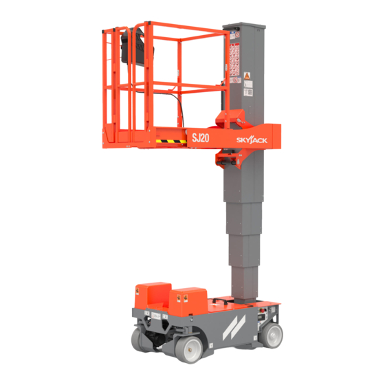
- Page 1 SERVICE MANUAL SJ20 VERTICAL MAST LIFTS 238886ABA November 16, 2021 ANSI/CSA...
- Page 2 This manual is based on serial numbers: SJ20: A601 000 001 & above Please refer to the website (www.skyjack.com) for contact information, other serial numbers, the most recent technical manuals, and USB software.
- Page 3 It may also be used to alert against unsafe practices. IMPORTANT IMPORTANT indicates a procedure essential for safe operation and which, if not followed, may result in a malfunction or damage to the MEWP . SJ20 238886ABA...
- Page 4 Notes 238886ABA SJ20...
-
Page 5: Table Of Contents
1.7-10 Optional equipment and attachments ..........21 SJ20... - Page 6 No Lift from Base Controls ............58 238886ABA SJ20...
- Page 7 Railing Maintenance and Repair . . . . . . . . . . . . . . . . . . . . . . . . . . . . . . . . . . . . . . . . . . . . . . . . . . . . . 105 SJ20...
- Page 8 Notes 238886ABA SJ20...
-
Page 9: Section 1 - Scheduled Maintenance
3000 hours, whichever occurs first. Any defective specifications and dimensions are subject to change part will be replaced or repaired by your local Skyjack without notice. dealer at no charge for parts or labor. In addition, all products have a 5 year structural warranty. -
Page 10: Maintenance And Inspection Schedule
MEWP . relative law provisions obtaining in the country. Consult Skyjack’s Service Department for optional Before attempting any repair work, disconnect the tires specifications and installation. main power connectors. -
Page 11: Hydraulic System & Component Maintenance And Repair
The use of cloth to strain the oil should be avoided to prevent lint from getting into the system. 6. When removing any hydraulic component, be sure to cap and tag all hydraulic lines involved. Also, plug the ports of the removed components. SJ20 238886ABA... -
Page 12: About This Section
MEWP parked on a flat and level surface ▪ Legend Disconnect the batteries by disconnecting the ▪ Pass main power connectors. Fail Repair any damaged or malfunction ▪ components before operating MEWP . Repaired Keep records on all inspections. ▪ Not applicable 238886ABA SJ20... -
Page 13: Owner's Annual Inspection Record
The Owner’s annual inspection record is located on the scissor assembly. It must be filled out after an annual inspection has been completed. Do not use the MEWP if an inspection has not been recorded in the last 13 months. SJ20 238886ABA... -
Page 14: Frequent/Periodic/Annual/Pre-Delivery Inspection Checklist
199341ACA Comments: The undersigned has made sure that all areas in the list have received an inspection. The undersigned has told the machine owner of all inconsistencies in the inspection and corrected them before machine operation. Owner: User: 238886ABA SJ20... -
Page 15: Visual And Daily Maintenance Inspections
Make sure that the MEWP is on a firm, level All hydraulic cylinders ▪ surface before you do the visual and daily All hydraulic manifolds maintenance inspections. If you do not obey, there ▪ is a risk of machine damage. The ground area below the MEWP ▪ SJ20 238886ABA... -
Page 16: Base
WARNING ▪ there is no damage. Do not use tires other than the tires that Skyjack Steer cylinder assembly, specifies for this MEWP . Do not mix different types of tires or use tires that are not in good condition. - Page 17 ▪ or missing parts and there is no visible damage. C - Annual inspection ▪ Make sure the castle nuts are in position ▪ and are tight. Make sure the cotter pins are correctly ▪ Figure 01 installed. SJ20 238886ABA...
-
Page 18: Platform Assembly
Fall-protection anchorages, Make sure that the fall-protection anchorages ▪ are correctly attached. Make sure the fall protection anchorages show ▪ no signs of visible damage, deformation, or cracks. 238886ABA SJ20... -
Page 19: Hydraulic/Electrical Compartment
3. If applicable, do a check on the battery fluid be at or a small distance above the top mark. levels. If the plates do not have a minimum 13 mm (1/2 inch) of solution above them, add distilled or demineralized water. SJ20 238886ABA... - Page 20 Make sure there is no visible damage. ▪ Wheel/motor assembly, Make sure there are no loose or missing ▪ fasteners. Make sure there is no visible damage. ▪ Make sure there are no loose or missing wires. ▪ 238886ABA SJ20...
-
Page 21: Lift Mechanism
Make sure the bolts are tight. ▪ Make sure there are no loose or missing parts. ▪ Make sure there are no loose or missing parts. ▪ Make sure there is no visible damage. ▪ Make sure there is no visible damage. ▪ SJ20 238886ABA... - Page 22 Notes 238886ABA SJ20...
-
Page 23: Section 2 - Maintenance Tables And Diagrams
MEDIUM 90°, FEMALE, 37° JIC, SWIVEL 100R13 SHORT 90°, FEMALE, 37° JIC, SWIVEL SHORT 90°, FEMALE, 37° JIC, SWIVEL 100R17 FEMALE, 37° JIC, SWIVEL REUSABLE MALE PIPE THREAD FITTING 300 PSI REUSABLE MALE PIPE THREAD FITTING NO FITTING 300 PSI SJ20 238886ABA... - Page 24 FEMALE, 37° JIC, SWIVEL 100R19 MEDIUM 90°, FEMALE, 37° JIC, SWIVEL FEMALE, 37° JIC, SWIVEL 100R19 LONG 90°, FEMALE, 37° JIC, SWIVEL FEMALE, 37° JIC, SWIVEL 100R19 LONG 90°, FEMALE, SAE ORFS, SWIVEL FEMALE, SAE ORFS, SWIVEL 100R15 238886ABA SJ20...
-
Page 25: Specifications And Features
Specifications and Features Section 2 – Maintenance Tables and Diagrams Table 2.2 Specifications and Features Model SJ20 Weight * 1107 kg (2440Ib) Overall Width 0.80 m (31.5 in) Overall Length 1.37 m (54 in) 0.69 m x 0.91 m Platform Size (Inside) (27.13 in x 35.66 in) -
Page 26: Maximum Platform Capacities (Evenly Distributed)
Model Rating Capacity Capacity Force (side-to-side x front-to-back) 0 m/s 159 kg 159 kg 200 N SJ20 Indoor 1 person 1 person 1.5° x 2.5° (0 mph) (350 lb) (350 lb) (45 lbf) 2066AA NOTE Occupants and materials are not to exceed the rated load. Refer to the capacity label at the entrance of the platform and the mast assembly. -
Page 27: Floor Loading Pressure Ansi/Csa
WARNING Do not use tires other than the tires that Skyjack specifies for this MEWP . Do not mix different types of tires or use tires that are not in good condition. -
Page 28: Torque Specifications
Mast to Base Mounting Bolts BOLT, Hex head (3/8"-16 x 1" Grade 8) Lift Cylinder Mounting Bolts BOLT, Hex head (3/8"-16 x 1-1/4" Grade 8) Lift Cylinder Plate Mounting Bolts BOLT, Socket - Wire lock (1/4"-20 x 1-3/4" Grade 5) 2125AB 238886ABA SJ20... -
Page 29: Torque Specifications For Fasteners (Imperial)
1/2-20 ft-lb 2200 1640 3560 2660 1 1/2-12 * Inch-Pound Force = in-lb Foot-Pound Force = ft-lb 1329 2983 2224 4827 3606 Newton-Meter = Nm 1612 NOTE Lubed includes lubricants such as lubrizing oil, grease or uncured loctite. SJ20 238886ABA... -
Page 30: Torque Specifications For Fasteners (Metric)
2849 2137 ft-lb 1886 1415 2699 2024 M36 x 4.00 2557 1918 3659 2744 1613 Inch-Pound Force = in-lb Foot-Pound Force = ft-lb Newton-Meter = Nm NOTE: Lubed includes lubricants such as lubrizing, oil, grease, or uncured Loctite. 238886ABA SJ20... -
Page 31: Torque Specifications For Hydraulic Couplings & Hoses
Max. Min. Max. Min. Max. Min. Max. Min. Max. 1/4" 6.75 1/4" 3/8" 3/8" 1/2" 27.66 1/2" 5/8" 46.33 5/8" 3/4" 72.33 3/4" 1" 100.5 1" 1 1/4" 101.5 1 1/4" 1 1/2 1 1/2 2" 2" 1614 SJ20 238886ABA... - Page 32 Notes 238886ABA SJ20...
-
Page 33: Section 3 - System Component Identification And Schematics
Section 3 – System Component Identification and Schematics SJ20 238886ABA... -
Page 34: Electrical Symbol Chart
RESISTOR TILT SWITCH TRANSISTOR SINGLE POLE VACUUM POTENTIOMETER SINGLE THROWN LEVEL SENSOR SWITCH RELAY DOUBLE POLE TEMPERATURE SINGLE POLE DOUBLE POLE DOUBLE THROW SWITCH DOUBLE THROW SINGLE THROW RELAY RELAY RELAY TRIPLE POLE RHEOSTAT DIODE DOUBLE THROW RELAY 238886ABA SJ20... -
Page 35: Hydraulic Symbol Chart
NORMALLY THREE WAY VALVE MOTOR OPEN PORT CLOSED VALVE THREE POSITION TWO POSITION TWO POSITION FOUR WAY TWO WAY THREE WAY VALVE CLOSED CENTER NORMALLY CLOSED PORT OPEN VALVE PRESSURE PILOT LINES Dashed MAIN LINES Solid TRANSDUCER SERVO SJ20 238886ABA... -
Page 36: Wire Number And Color Code
This table is to be used as a wire number/color reference for electrical drawings and schematics. All wire numbers will retain their original color coding, for example if wire 7 is red, wire 7A, 7B, and 7C will also be red. 238886ABA SJ20... -
Page 37: Hydraulic Parts List
STEER CYLINDER 234711 VALVE, Check 234269 FILTER, 7 Micron return 234270 FILTER, 7 Micro return 234720 MANIFOLD, SJ20 Main 234654 VALVE, Flow control 234703 PUMP , 3.59 CC gear 234715 VALVE, 2000 PSI relief 234716 VALVE, 3000 PSI cross port relief... -
Page 38: Electrical Parts List
SWITCH, Toggle - Diagnostic 115573 SWITCH, Toggle - Brake release 171911 SWITCH, Toggle - Outdoor option (Optional) 147054 SWITCH, Platform horn 220494 SWITCH, SGLE option (Optional) 149536 SWITCH, Base - Idle/Platform/Base 147053 SWITCH, Emergency stop - Base control 238886ABA SJ20... -
Page 39: Hydraulic Connections
Hydraulic Connections Section 3 – System Component Identification and Schematics 3.6 Hydraulic Connections Lift Cylinder Power Unit Right Left Steer Steer Steer Cylinder M234628AA SJ20 238886ABA... -
Page 40: Platform Control Box Wiring
INDOOR LIGHT BLACK YELLOW CAN HI LIFT ORANGE/RED GREEN CAN LO DECK EXT GRAY/ORANGE BLACK LOADCELL PWR BROWN/WHITE BLACK 120A CAN LO CAN LOW GREEN CAN HI CAN HIGH YELLOW 28-29 WHITE 120A SPARE BLACK WHITE WHITE WHITE M234028AD 238886ABA SJ20... -
Page 41: Platform Control Cable Wiring
08C-PU/WH-20 08-PU/WH-20 51-BK/GN-20 00-WH-18 00-WH-18 60-BK/RD/GN-20 EMERGENCY 07-RED-16 STOP 08-PU/WH-18 120-BK-20 08-PU/WH-18 09-OR/RD-20 12A-GY/OR-20 82A-BR/WH-20 SCANL CANL-GN-20 CANH-YL-20 120 OHM SCANH 120A-BK-20 00-WH-18 SPLICE SHOULD BE IN CONNECTOR SHELL 16 PIN X1 16 PIN X1 CONNECTOR CONNECTOR M220967AA SJ20 238886ABA... -
Page 42: Platform Control Box Wiring - Sgle
INDOOR LIGHT BLACK YELLOW CAN HI LIFT ORANGE/RED GREEN CAN LO DECK EXT GRAY/ORANGE BLACK LOADCELL PWR BROWN/WHITE BLACK 120A CAN LO CAN LOW GREEN CAN HI CAN HIGH YELLOW WHITE 28-29 WHITE 120A SPARE BLACK WHITE WHITE M234135AD 238886ABA SJ20... -
Page 43: Platform Control Cable Wiring - Sgle
08-PU/WH-18 HORN 08-PU/WH-18 08C-PU/WH-20 08-PU/WH-20 51-BK/GN-20 00-WH-18 00-WH-16 60-BK/RD/GN-20 EMERGENCY 07-RED-16 STOP 08-PU/WH-18 120-BK-20 08-PU/WH-18 09-OR/RD-20 12A-GY/OR-20 82A-BR/WH-20 CANL-GN-20 SCANL SGLE KIT 09-OR/RD-20 CANH-YL-20 120 OHM SCANH 120A-BK-20 00-WH-18 16 PIN X1 16 PIN X1 CONNECTOR CONNECTOR M234136AD SJ20 238886ABA... -
Page 44: Beeper
WIRE LABEL BLACK 3.12 Base Limit Switch WIRE CAVITY BROWN BLUE BLACK BLACK/WHITE YELLOW/GREEN NOT USED 3.13 Platform Limit Switches TO PIN 7 Service Position TO BK/WH TO BK/WH TO PIN 5 Deck Extended TO PIN 6 M215817AC_M234204AC_M234218AD_M234219AE 238886ABA SJ20... -
Page 45: Motor And Controller Connections
Motor and Controller Connections Section 3 – System Component Identification and Schematics 3.14 Motor and Controller Connections Power Unit Right Motor Left Motor M234099AC SJ20 238886ABA... -
Page 46: Mast Cable
CANHI-YL-20 SCANL CANLO-GN-20 CANLO-GN-20 TO LOAD CELL SDRN JUNCTION BOX SDRN BASE INTERFACE MAST INTERFACE APPLY EXTRA LABLE TO J1 WIRE POSITION WIRE LABEL 08C-PU/WH-18 OUTDR JUMPER 07-RD-16 08-PU/WH-18 CAN HI 08C-PU/WH-18 CAN LO 08C-PU/WH-18 OUTDR JUMPER M234109AC 238886ABA SJ20... -
Page 47: Major Component Identification
3.16 Major Component Identification Platform Control Console Load Cell Junction Box Platform Maintenance Lock Load Cells ZAPI Controller Deck Extended Limit Switch Main Disconnect Switch Base Controls Charger Base Limit Switch Service Position Limit Switch M69442AB SJ20 238886ABA... -
Page 48: Hydraulic Schematic
3.17 Hydraulic Schematic LIFT CYLINDER PLATFORM STEERING CYLINDER 3000 psi LIFT 3H-14 4H-23 4H-24 2000 psi CHASSIS 3.59 CC/REV 0.079 in 2900 - 6400 RPM 2H-13 M234001AB SJ20 238886ABA... -
Page 49: Base Control Wiring
TO ZAPI A CONN TO ZAPI B CONN BRAKE MAST RELASE CABLE SWITCH DIAG CONN HORN BP-29 MOTION BEEPER S10 KEY SWITCH EMERGENCY LIFT/LOWER STOP DIAGNOSTIC SWITCH 30ACR CB1 15A BREAKER CB2 10A BREAKER BRAKE RELASE SWITCH HORN M234197AB SJ20 238886ABA... -
Page 50: Main Harness - Zapi A
PIN 16 - N/U PIN 34 - N/U TO MAST LOWER SOLENOID PIN 35 - N/U PIN 17 - CHAL - BLUE/WHITE PIN 1 - 13B ORANGE PIN 18 - CANL - GREEN PIN 2 - 13 ORANGE M234155AE SJ20 238886ABA... -
Page 51: Main Harness Wiring - Zapi A
CANH-YL-20 CHBR-BU-18 00R-WH-18 TO MOTOR CONTROLS 19A-OR/BK-18 23-BK/WH-18 14-BK-18 13B-OR-18 19-OR/BK-16 30R-BU/RD-18 13-OR-18 30L-BU/RD-18 CANH-YL-20 TMPR-BK/WH-18 TMPL-BK/WH-18 S08L D30L TO TELE MATIC BRK2 TO LEFT TO LEFT MOTOR TO MAST TO LOWER M234155AE_pg2 BRAKE SENSOR CONTROL BOX LOWER SJ20 238886ABA... -
Page 52: Main Harness - Zapi B
TO MAST POSITION OPTION LIMIT SW 14A-BK-18 21-BL/RD-18 60-BK/GN-18 03C-GN/PU-18 13A-OR-18 14A-BK-18 10-BU/WH-18 13A-OR-18 19B-GN/BK-18 10-BL/WH-18 TO MOTOR 07-RD-18 TO LOWER BASE CONTROLLER 19B-GN/BK-18 CONTROL 30-BL/RD-18 30-BL/RD-18 07-RD-18 08C-PU/WH-18 49-GN-16 08L-PU/WH-18 30A-BL/RD-18 60-BK/GN-18 03C-GN/PU-18 22-OR/BU-18 49-GN-16 30A-BL/RD-18 M234156AC SJ20 238886ABA... -
Page 53: Electrical Schematic
MOTOR MOTOR OUTDOOR + BRAKE - - BRAKE + SWITCH P9-2 P7-2 HEIGHT MOTOR BRAKE P9-1 P7-1 SENSOR PL-3 D05B OUTDOOR INDOOR OPTION X1-14 LIGHT X3-10 BATTERY CHARGE X1-15 INDICATOR WHITE X1-16 X2-6 X3-11 3.22 Electrical Schematic M234002AC SJ20 238886ABA... - Page 54 Notes 238886ABA SJ20...
-
Page 55: Section 4 - Troubleshooting Information
“probable cause.” The information in the right-hand column, in bold text, represents the “remedy” to the “probable cause” directly beside it. See the example below for clarification. 1. Probable cause Remedy SJ20 238886ABA... -
Page 56: Electrical System
16. Loose or broken wire 07 from base key switch to Check continuity. Replace if defective. machine controller pin B12 17. Loose or broken wire 07 from base key switch to upper Check continuity. Replace if defective. control box E-Stop switch S4 238886ABA SJ20... -
Page 57: No Lift Or Steer Functions
Check continuity. Replace if defective. steer (4H-24) coils 4.2-3 No Lift from Base or Platform 1. Loose or broken wire 14 from lift coil 3H-14 to Check continuity. Replace if defective. machine controller pin A25 2. Defective coil 3H-14 Replace coil SJ20 238886ABA... -
Page 58: No Lower From Base Or Platform
Check wiring and switch. Repair or replace if 3. Defective enable switch or wiring on upper contol joystick defective. 4. Defective ground wire 00 from machine controller Check continuity. Replace if defective. pin P-32 to B- 5. Defective Joystick Replace if defective 238886ABA SJ20... -
Page 59: No Lift/Lower From Platform Controls
Check continuity. Replace if defective. machine controller pin A30 8. Loose or broken wire 30R from BK1 pin P7-2 to Check continuity. Replace if defective. machine controller pin A28 9. Defective brake BRK1 or BRK2 Check brakes. Replace if defective. SJ20 238886ABA... -
Page 60: Hydraulic System
2. Steer crossover relief valve RV2 set too low or Check and adjust valve setting. Replace if stuck open. defective. Check cylinder and all steer linkage. Repair or 3. Steer cylinder C5 bypassing, or mechanically binding replace defective componants as required. 238886ABA SJ20... -
Page 61: Section 5 - Procedures
5. Turn the main power disconnect switch to the “ ” off position. After completing any procedure which involves modifying, adjusting, or replacing any hydraulic or electrical components, perform all of the function tests given in your unit’s operation Manual. SJ20 238886ABA... -
Page 62: Display Module
M65-M2_TEMP MOTOR TEMPERATURE M140-LOW_BATT LOW BATTERY VOLTAGE - LIFT LOCKED M66-LOW_BATT LOW BATTERY M141-TILT_ERXX XX TILT SENSOR ERROR M74-CTRL_ERR DRIVER SHORT CIRCUIT M142-CHARGING IN CHARGE M75-CTRL_ERR CONTACTOR DRIVER FAULTY M144-CTRL_ERR INTERNAL BUS ERROR M78-JSTK_VERR ACCELERATOR VOLTAGE NOT OK 238886ABA SJ20... - Page 63 EV XX COMMON PILOT M194-CTRL_ERR AUXILIARY BATTERY SHORT CIRCUIT M233-CTRL_ERR SHORT CIRCUIT POWER MOSFET M195-BRK1_ERR SHORT CIRCUIT POSITIVE COIL BRAKE M234-CTRL_ERR EV SHORT-CIRCUIT M196-M1_ERR SHORT CIRCUIT MOTOR PHASE M235-CTRL_ERR CTRAP THRESHOLD M197-CTRL_ERR SECONDARY INCORRECT VERSION M236-CTRL_ERR CURRENT GAIN SJ20 238886ABA...
- Page 64 NOT READY CONTROL DRIVER POWER S65-M3_TEMP MOTOR TEMPERATURE S159-CTRL_ERR HVIL FAIL S66-LOW_BATT LOW BATTERY S160-TILTED MACHINE TILTED S74-CTRL_ERR DRIVER SHORT CIRCUIT S161-M3_ERR HIGH RPM S75-CTRL_ERR CONTACTOR DRIVER FAULTY S163-M3_ERR ED SLIP NOT MATCHED S78-JSTK_VERR ACCELERATOR VOLTAGE NOT OK S169-M3_ERR_XX ENCODER ERROR XX 238886ABA SJ20...
- Page 65 TEMP SENSOR FAULT S10-CTRL_ERR INCORRECT RAM MEMORY S251-CTRL_ERR INCORRECT BATTERY S211-M3_ERR STALL ROTOR S253-CTRL_ERR FAULT FIELD ORIENTED CONTROL S212-M3_ERR POWER NOT PAIRED SHORT CIRCUIT CONTROL PILOT COIL S254-CTRL_ERR BRAKE S213-C1_ERR LC POSITIVE COIL OPEN S214-2H-13_ERR OPEN COIL EVP SJ20 238886ABA...
-
Page 66: Wheel Reinstallation And Torquing Procedure
Contaminants include dust, dirt, sand, water or other foreign particles. 4. Install the inner and outer bearings with the tapered end first. The grease should allow the bearings to stick to the bearing cups inside the wheel assembly. 238886ABA SJ20... - Page 67 8. To limit rust bleed, it is recommended that a few drops of grease be applied to the two small 5. Use a hub puller to remove the wheel from the tapped holes on the front wheels. motor. SJ20 238886ABA...
- Page 68 4. Loosen the castle nut to remove the torque. Do not rotate the wheel. 5. Finger tighten the castle nut until it is snug. NOTE The castle nut should be free to rotate, with the only restraint being the cotter pin. 238886ABA SJ20...
-
Page 69: Battery Maintenance
MEWP . manual. Charging Solid Charger output is output yellow active. Charge Current profile/ algorithm N/A. error or fault/ display error code Select Current charge charging N/A. profile algorithm SJ20 238886ABA... -
Page 70: Charger Profiles
330 - 425 Ah flooded #73 (P-0-7-3) Trojan - T105 ELPT Flooded, 6V, 225 Ah 150 - 250 Ah 6V, 8V, 12V flooded #3 (P-0-0-3) *The batteries used for these charger profiles are connected in a series-parallel circuit. Delta-Q IC-650 Charger Profiles 238886ABA SJ20... -
Page 71: Charger Troubleshooting
Internal charger fault. Disconnect AC and battery from charger for a minimum of 30 seconds. If it fails again, contact Power Factor Correction (PFC) Failure: PFC F-0-0-2 Skyjack service. excessive leakage fault. F-0-0-3 PFC has taken too long to boost. -
Page 72: Charger Error Codes
Battery connections are loose or corroded. Check ▪ connections. Extra loads. Turn off other devices running on the battery ▪ This error automatically clears once the charger is reset ▪ by cycling DC or by loss of AC for over 10 minutes. ▪ 238886ABA SJ20... - Page 73 New batteries, if charged when already full, may also cause this error. Disconnect and reconnect the batteries a few times. Check the battery voltage and cable connections. ▪ This error automatically clears once the condition has ▪ been corrected. SJ20 238886ABA...
- Page 74 Internal charger error. Disconnect AC and the battery for ▪ a minimum of 30 seconds and retry. has triggered an alarm If the problem persists, contact Delta-Q Technologies. ▪ This error automatically clears once the condition has ▪ been corrected. 238886ABA SJ20...
- Page 75 E-0-4-6 Invalid PDO Length This error automatically clears once the condition has ▪ been corrected A battery or some other source has been connected to ▪ E-0-4-7 Platform overvoltage alarm the charger that exceeds the hardware’s design limits. SJ20 238886ABA...
-
Page 76: Mast Lubrication
(1-1/2") wide strip along the outside front corners of each mast section. Do not apply lubricant to the topmost outer mast. 5. Wait 10 minutes for the lubricant to dry. 6. Use the base controls to retract the mast. Lubricate Lubricate Lubricate 238886ABA SJ20... -
Page 77: Inner Mast Lubrication
4. Remove and set aside the top mast cover and wing screws. 5. Apply DuPont Multi-Use Lubricant (158692) or any PTFE wax based dry lubricant, behind and around all top wear pads in each section of the mast. SJ20 238886ABA... -
Page 78: Platform Removal
4. Loosen the strain relief from the bottom of the housing and pull out the limit switch wires. 7. Extend the platform a little bit so you can access the front rollers. 8. Remove and set aside the two front rollers. 238886ABA SJ20... - Page 79 10. Remove the bolts and nuts that secure the lower 12. Disconnect the connection from the junction box platform to the mast. to the mast cable. 11. Make sure the load cells stay attached to the mast. SJ20 238886ABA...
- Page 80 13. Remove and set aside the hardware from the junction box. 14. Put the junction box on the chassis. 15. Tilt the lower platform backwards. 16. Use an appropriate lifting device or a second person to help remove the lower platform. 238886ABA SJ20...
-
Page 81: Platform Installation
4. Use the screws removed earlier to secure the junction box to the lower platform. 3. Use the bolts and nuts removed earlier to secure the lower platform to the mast load cells. 5. Connect the junction box connector to the mast electrical connector. SJ20 238886ABA... - Page 82 7. Insert the front rollers between the traverse platform and the lower platform. 13. Connect the platform control cable to the mast electrical housing. 8. Use the bolts and washers removed earlier to secure the front rollers. 9. Push the platform in fully. 238886ABA SJ20...
-
Page 83: Lift Cylinder Removal
2. Disconnect the hydraulic hose from the bottom of 4. Remove and set aside the hardware from the the holding valve manifold. Put a cap and plug on bottom of the chassis that secures the lift cylinder. all open hydraulic ports and fittings. SJ20 238886ABA... - Page 84 7. Use lifting straps to raise the lift cylinder out of the knob from the holding valve manifold. mast. 8. Set aside the lift cylinders on a protective surface. 6. Remove and set aside the mast cover and wing screws. 238886ABA SJ20...
-
Page 85: Lift Cylinder Installation
2. Use the bolts and washers removed earlier to secure the lift cylinder from the bottom of the 4. Install the hex standoff and red knob on the chassis. holding valve manifold. SJ20 238886ABA... - Page 86 7. Put the mast cover on top of the mast. valve coil. 8. Fasten it in place with the wing screws removed earlier. 6. Use the bolts and washers removed earlier to secure the lift cylinder to the mast. 238886ABA SJ20...
-
Page 87: Mast And Lift Cylinder Removal
5. Cut zip ties along the cable bundles to free the 10. Cut the tie wraps that secure the AC power cable mast cable. to the cable carrier and existing cable bundles. SJ20 238886ABA... - Page 88 17. Use lifting straps to raise the mast assembly above the chassis. 18. Set aside the mast assembly. 13. Disconnect the hydraulic hose from the bottom of the holding valve manifold. Put a cap and plug on all open hydraulic ports and fittings. 238886ABA SJ20...
-
Page 89: Mast And Lift Cylinder Installation
4. Install the hex standoff and red knob on the holding valve manifold. 2. Use the bolts and washers removed earlier to 5. Connect the electrical connector to the holding secure the mast assembly to the chassis. valve coil. SJ20 238886ABA... - Page 90 7. Open the service compartment cover. 8. Connect the mast electrical connector to the main harness. 12. Use new pop rivets to secure the AC inlet to the 9. Use tie wraps to secure the mast cable to the chassis. existing cable bundles. 238886ABA SJ20...
- Page 91 13. Use the nut removed earlier to secure the green ground wire from the AC inlet to the chassis 14. Use tie wraps to secure the AC power cable to the existing cable bundles. 15. Install the platform. Refer to section 5.8 Platform Installation. SJ20 238886ABA...
-
Page 92: Wear Pad Replacement
Mast 5 4. At the rear of the machine, drill out the rivets that secure the AC inlet to the chassis. 5. Pull out the AC inlet. 6. Disconnect the wires from the back of the AC inlet. 238886ABA SJ20... - Page 93 9. Remove and set aside the screws that secure the 12. Remove and set aside the cable clips from the mast electrical housing to the mast. mast cable. 10. Remove the rivets and washers that secure the AC outlet to the mast. Set aside the washers. SJ20 238886ABA...
- Page 94 Set the steel weights and mast cable aside. 16. Remove and discard the front wear pads and pop 14. Use hoist rings and lifting straps to raise mast 5 rivets from the bottom of the mast. until the bottom wear pads are visible. 238886ABA SJ20...
-
Page 95: Remove Mast 4 Through 2 And Wear Pads
17. Remove mast 5 completely and set it aside on a protective surface. 2. Wrap lifting straps around the mast below the top wear pads. 3. Raise the mast until the bottom wear pads are visible. SJ20 238886ABA... - Page 96 6. Remove mast 4 completely and set it aside on a protective surface. 5. Remove and discard the pop rivets and front wear pads at the bottom of the mast. 7. Repeat steps 1 through 6 with the remaining masts until there is only one mast left. 238886ABA SJ20...
-
Page 97: Replace The Top Wear Pads
(234168) to the rear of the mast. 4. Repeat steps 2 and 3 for masts 2 through 4. 2. Use new pop rivets to attach two new thick and short wear pads (234170) to the front of the mast. SJ20 238886ABA... -
Page 98: Install The Mast Cable
3. Use the three cable clamps removed earlier to secure the mast cable to the cable carrier in three places. 4. Lower the rest of the mast cable down mast 1 while you install the next mast section. 238886ABA SJ20... -
Page 99: Install The Masts 2 Through 4 And Bottom Wear Pads
2. Use lifting straps to put mast 2 onto mast 1. Make sure the holding valve cutout faces the rear of the machine. 5. Use new pop rivets to attach two new thick and long wear pads (234171) to the front of the mast. SJ20 238886ABA... - Page 100 7. Use the three cable clamps removed earlier to 9. Put a weighted roller into the cable loop. secure the cable to the mast 2 cable carrier. 238886ABA SJ20...
-
Page 101: Install The Mast 5 And Bottom Wear Pads
2. Keep the mast 5 raised so that the bottom part is visible. 3. Use new thread rolling screws to attach two new thin and short wear pads (234169) to the rear of the mas. 12. Repeat steps 2 through 11 for masts 3 to 4. SJ20 238886ABA... - Page 102 7. Use new pop rivets and the washers removed earlier to mount the AC outlet box to the side of 5. Pull the mast cable out of mast 1 and lower it mast 5. between mast 4 and mast 5. 238886ABA SJ20...
- Page 103 10. Insert the weighted roller into the cable loop. to attach the mast cable to the inner face of mast 11. Fully lower mast 5 onto the chassis. 9. Raise mast 5 until the cable loop is visible. SJ20 238886ABA...
-
Page 104: Install The Lift Cylinders And Platform
Black wire to the bronze terminal ▪ White wire to the silver terminal ▪ 5.13-8 Install the lift cylinders and platform 1. Install the lift cylinders. Refer to section 5.10 Lift Cylinder Installation. 2. Install the platform. Refer to section 5.8 Platform Installation. 238886ABA SJ20... -
Page 105: Railing Maintenance And Repair
Section 5 – Procedures 5.14 Railing Maintenance and Repair Skyjack MEWPs have been designed to make sure compliance with the relevant design standards applicable for that particular unit at the time of manufacture. As such, any repairs made to the... - Page 106 Notes 238886ABA SJ20...
- Page 108 www.skyjack.com...
Need help?
Do you have a question about the SJ20 and is the answer not in the manual?
Questions and answers
what does driver short circuit code mean
For the Skyjack SJ20, a driver short circuit is indicated by error codes such as M241-COIL_ERRXX (short circuit coil EVAUX) or S138-SERVICE (service mode short circuit control pilot coil). These errors mean a short circuit has been detected in the respective coil or control pilot circuit, which can affect machine operation and may require service intervention to resolve the electrical fault.
This answer is automatically generated