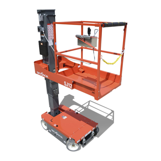
Skyjack SJ12 Service Manual
Vertical mast
Hide thumbs
Also See for SJ12:
- Operation manual (84 pages) ,
- Operating manual (60 pages) ,
- Operation and installation manual (36 pages)

Related Manuals for Skyjack SJ12


Summary of Contents for Skyjack SJ12
- Page 1 SERVICE MANUAL SJ12, SJ16 VERTICAL MAST 213558ADA January 17, 2022 ANSI/CSA, CE , AS...
- Page 2 This manual is for MEWPs with serial numbers: SJ12 & SJ16: A600 000 001 - A600 999 999 Please refer to the website (www.skyjack.com) for contact information, other serial numbers, the most recent technical manuals, and USB software.
- Page 3 It may also be used to alert against unsafe practices. IMPORTANT IMPORTANT indicates a procedure essential for safe operation and which, if not followed, may result in a malfunction or damage to the MEWP . SJ12, SJ16 213558ADA...
- Page 4 Notes SJ12, SJ16 213558ADA...
-
Page 5: Table Of Contents
Torque Specifications for Hydraulic Couplings & Hoses ........38 SJ12, SJ16... - Page 6 4.2-12 Steer Only Inoperative ............78 SJ12, SJ16...
- Page 7 Charger Maintenance ............98 SJ12, SJ16...
- Page 8 Railing Maintenance and Repair ........... . . 140 SJ12, SJ16...
- Page 9 Notes SJ12, SJ16 213558ADA...
- Page 10 Notes SJ12, SJ16 213558ADA...
-
Page 11: Section 1 - Scheduled Maintenance
2 years or 3000 hours, whichever occurs first. Any defective part will be replaced or repaired by your local Skyjack dealer at no charge for parts or labor. In addition, all products have a 5 year structural warranty. -
Page 12: Maintenance And Inspection Schedule
MEWP . relative law provisions obtaining in the country. Consult SKYJACK’s Service Department for optional Before attempting any repair work, disconnect the tires specifications and installation. main power connectors. -
Page 13: Hydraulic System & Component Maintenance And Repair
The use of cloth to strain the oil should be avoided to prevent lint from getting into the system. 6. When removing any hydraulic component, be sure to cap and tag all hydraulic lines involved. Also, plug the ports of the removed components. SJ12, SJ16 213558ADA... -
Page 14: Maintenance Hints
Dirty, dusty, high moisture environments may cause the hydraulic system to be contaminated more quickly. 2. Maintain a sufficient quantity of clean hydraulic oil of the proper type and viscosity in the hydraulic reservoir. 3. Keep all connections tight. SJ12, SJ16 213558ADA... -
Page 15: About This Section
Frequent PDI/Frequent inspection procedure, refer to service bulletins found Inspection every 200 days in our web site: www.skyjack.com for updates related or 200 hours. to service and maintenance of this MEWP . Perform Scheduled Maintenance and Inspection Annual... -
Page 16: Owner's Annual Inspection Record
The Owner’s annual inspection record is located on the mast assembly. It must be filled out after an annual inspection has been completed. Do not use the MEWP if an inspection has not been recorded in the last 13 months. SJ12, SJ16 213558ADA... -
Page 17: Frequent/Periodic/Annual/Pre-Delivery Inspection Checklist
Frequent/Periodic/Annual/Pre-Delivery Inspection Checklist Section 1 – Scheduled Maintenance 1.4 Frequent/Periodic/Annual/Pre-Delivery Inspection Checklist SJ12, SJ16 213558ADA... -
Page 18: General Inspections
Section 1 – Scheduled Maintenance General inspections 1.5 General inspections 1.5-1 Service Bulletins Go to www.skyjack.com and use your machine’s Do an inspection of the MEWP in this sequence. serial number to find related open service bulletins. WARNING 1.5-2 Annual Inspection Do not operate a MEWP that does not function Do a check on the machine’s service record to find... -
Page 19: Base Inspections
Make sure there are no loose or missing ▪ thoroughly with a terminal cleaning tool or fasteners and lock-pins. wire brush. Make sure the steer linkages and bushings are ▪ correctly attached. Make sure there is no visible damage. ▪ SJ12, SJ16 213558ADA... - Page 20 Make sure there is no dirt or blockages. ▪ WARNING Brakes (B, C) Do not use tires other than the tires that Skyjack B - Frequent/periodic/pre-delivery Inspection ▪ specifies for this MEWP . Do not mix different types Make sure there are no loose or missing of tires or use tires that are not in good condition.
- Page 21 Make sure the castle nut is in position and is ▪ tight. Figure 02 Make sure the cotter pin is correctly installed. ▪ If the cotter pin is not installed, refer to ▪ Torque Specifications for proper torque information. SJ12, SJ16 213558ADA...
- Page 22 Do a check on these areas for chafed, corroded, ▪ and loose wires: Base to platform cables and wiring harness ▪ Hydraulic and electrical compartment wiring ▪ harnesses. Motor controller ▪ Make sure the motor controller has no damage ▪ and is correctly attached. SJ12, SJ16 213558ADA...
-
Page 23: Mast Inspections
Refer to 5.9 Mast Lubrication Procedure for the Make sure there is no visible damage. ▪ ▪ mast lubrication procedure. Tilt sensor Make sure the tilt sensors are correctly ▪ attached and there is no visible damage. SJ12, SJ16 213558ADA... -
Page 24: Platform Inspections
Make sure that the documents are in good ▪ no signs of visible damage, deformation, or condition, and you can read them. cracks. Always put the manuals and other documents ▪ back in the storage box after use. SJ12, SJ16 213558ADA... -
Page 25: Function Tests
Before you do the function tests, look for the ▪ operation manual with the same serial number as your MEWP . The operation manual has the instructions on which tests to do and how to do them correctly and successfully. SJ12, SJ16 213558ADA... - Page 26 Notes SJ12, SJ16 213558ADA...
-
Page 27: Section 2 - Maintenance Tables And Diagrams
MEDIUM 90°, FEMALE, 37° JIC, SWIVEL 100R13 SHORT 90°, FEMALE, 37° JIC, SWIVEL SHORT 90°, FEMALE, 37° JIC, SWIVEL 100R17 FEMALE, 37° JIC, SWIVEL REUSABLE MALE PIPE THREAD FITTING 300 PSI REUSABLE MALE PIPE THREAD FITTING NO FITTING 300 PSI SJ12, SJ16 213558ADA... - Page 28 FEMALE, 37° JIC, SWIVEL 100R19 MEDIUM 90°, FEMALE, 37° JIC, SWIVEL FEMALE, 37° JIC, SWIVEL 100R19 LONG 90°, FEMALE, 37° JIC, SWIVEL FEMALE, 37° JIC, SWIVEL 100R19 LONG 90°, FEMALE, SAE ORFS, SWIVEL FEMALE, SAE ORFS, SWIVEL 100R15 SJ12, SJ16 213558ADA...
-
Page 29: Specifications And Features - Ansi/Csa
4.9 L (1.3 gal) 4.9 L (1.3 gal) 1835AB * Weights are approximate; refer to serial nameplate for specific weight. ** Refer to Section 6.4 Move the MEWP for Transport in the Operation manual for more details. SJ12, SJ16 213558ADA... -
Page 30: Specifications And Features - Ce, As
ATF Dexron III Tank Capacity 4.9 L 4.9 L 1838AB * Weights are approximate; refer to serial nameplate for specific weight. **Refer to Section 6.4 Move the MEWP for Transport in the Operation manual for more details. SJ12, SJ16 213558ADA... -
Page 31: Maximum Platform Capacities (Evenly Distributed) Ansi/Csa
12.5 m/s Option 2073AA NOTE Occupants and materials are not to exceed rated load. Refer to the capacity label at the entrance of the platform and the mast assembly for additional information and models equipped with options. SJ12, SJ16 213558ADA... -
Page 32: Floor Loading Pressure Ansi/Csa
NOTE The LCP or that an individual surface can withstand varies from structure to structure and is generally determined by the engineer or architect for that particular structure. Floor Loading Pressure SJ16 SJ12 SJ12, SJ16 213558ADA... -
Page 33: Floor Loading Pressure - Ce, As
NOTE The LCP or that an individual surface can withstand varies from structure to structure and is generally determined by the engineer or architect for that particular structure. Floor Loading Pressure SJ16 SJ12 SJ12, SJ16 213558ADA... - Page 34 Intermixing tires of different types or using tires of types other than those originally supplied with this equipment can adversely affect stability. Therefore, replace tires only with the exact original Skyjack- approved type. Failure to operate with matched approved tires in good condition may result in death or serious injury.
-
Page 35: Torque Specifications
BOLT, Hex head (5/16”-18 x 3/4”, Grade 8) (Mast 4, SJ16) Roller Mount Left/Right BOLT, Hex head (5/16”-18 x 3/4”, Grade 8) (Mast 4, SJ16) Chain Mount Assy (Mast 5, SJ16) BOLT, Hex head (5/16”-18 x 3/4”, Grade 8) 1909 SJ12, SJ16 213558ADA... -
Page 36: Torque Specifications For Fasteners (Imperial)
2200 1640 3560 2660 * Inch-Pound Force = in-lb Foot-Pound Force = ft-lb 1 1/2-12 1329 2983 2224 4827 3606 Newton-Meter = Nm 1612 NOTE Lubed includes lubricants such as lubrizing oil, grease or uncured loctite. SJ12, SJ16 213558ADA... -
Page 37: Torque Specifications For Fasteners (Metric)
2137 ft-lb 1886 1415 2699 2024 M36 x 4.00 2557 1918 3659 2744 1613 Inch-Pound Force = in-lb Foot-Pound Force = ft-lb Newton-Meter = Nm NOTE: Lubed includes lubricants such as lubrizing, oil, grease, or uncured Loctite. SJ12, SJ16 213558ADA... -
Page 38: Torque Specifications For Hydraulic Couplings & Hoses
Min. Max. Min. Max. Min. Max. Min. Max. 1/4" 6.75 1/4" 3/8" 3/8" 1/2" 27.66 1/2" 5/8" 46.33 5/8" 3/4" 72.33 3/4" 1" 100.5 1" 1 1/4" 101.5 1 1/4" 1 1/2 1 1/2 2" 2" 1614 SJ12, SJ16 213558ADA... -
Page 39: Section 3 - System Component Identification And Schematics
Section 3 – System Component Identification and Schematics SJ12, SJ16 213558ADA... -
Page 40: Electrical Symbol Chart
TILT SWITCH TRANSISTOR SINGLE POLE VACUUM POTENTIOMETER SINGLE THROWN LEVEL SENSOR SWITCH RELAY DOUBLE POLE TEMPERATURE SINGLE POLE DOUBLE POLE DOUBLE THROW SWITCH DOUBLE THROW SINGLE THROW RELAY RELAY RELAY TRIPLE POLE RHEOSTAT DIODE DOUBLE THROW RELAY SJ12, SJ16 213558ADA... -
Page 41: Hydraulic Symbol Chart
THREE WAY VALVE MOTOR OPEN PORT CLOSED VALVE THREE POSITION TWO POSITION TWO POSITION FOUR WAY TWO WAY THREE WAY VALVE CLOSED CENTER NORMALLY CLOSED PORT OPEN VALVE PRESSURE PILOT LINES Dashed MAIN LINES Solid TRANSDUCER SERVO SJ12, SJ16 213558ADA... -
Page 42: Wire Number And Color Code
This table is to be used as a wire number/color reference for electrical drawings and schematics. All wire numbers will retain their original color coding, for example if wire 7 is red, wire 7A, 7B, and 7C will also be red. SJ12, SJ16 213558ADA... -
Page 43: Hydraulic Component Parts List
MOTOR, Drive (Right) 139412 MOTOR, Drive (Left) 151270 PUMP , DC motor 146559 PUMP , Hand 122420 QUICK DISCONNECT 108721 ORIFICE (0.055”) (Lowering speed) (SJ12) 159416 ORIFICE (0.043”) (Lowering speed) (SJ16) 141518 ORIFICE (0.031”) 158852 CONTROLLER (Priority flow) SJ12, SJ16 213558ADA... -
Page 44: Electrical Component Parts List
BATTERY CHARGER INDICATOR (Platform control console) BP-29 103057 BEEPER, 4-28 VDC Slow pulsing (Base control centre) BP-49 146649 HORN, 24V (Low tone) 117325 CIRCUIT BREAKER (15 Amp) 117325 CIRCUIT BREAKER (15 Amp) Parts list continued on following page. SJ12, SJ16 213558ADA... - Page 45 CONTROLLER ASSEMBLY 147054 N.O. CONTACT, Horn (Platform control console) 147053 N.C. CONTACT, Off/Platform/Base (Base control centre) 147054 N.O. CONTACT, Off/Platform/Base (Base control centre) 147053 N.C. CONTACT, Emergency stop (Base control centre) 195940 HOUR METER 157375 SWITCH, Tilt SJ12, SJ16 213558ADA...
-
Page 46: Cylinders And Port Identifications
Section 3 – System Component Identification and Schematics Cylinders and Port Identifications 3.6 Cylinders and Port Identifications Steer Cylinder Lift Cylinder Lowering Orifice 2H-13 Emergency Lowering Valve To Main Manifold M157322AB_3 SJ12, SJ16 213558ADA... -
Page 47: Wheel Brake And Port Identifications
3.7 Wheel Brake and Port Identifications Wheel Brake (Right) To Brake Manifold Wheel Brake (Left) To Brake Manifold To Drive Motor (Left) To Main Manifold Drive Motor (Right) To Drive Motor (Right) Drive Motor (Left) To Main Manifold M149106AA_S3 SJ12, SJ16 213558ADA... -
Page 48: Powerpack And Port Identifications
Section 3 – System Component Identification and Schematics Powerpack and Port Identifications 3.8 Powerpack and Port Identifications To Main Manifold To Main Manifold Test Port Relief Valve Pump Powerpack Manifold Motor M151460AD_s3b SJ12, SJ16 213558ADA... -
Page 49: Platform Control Box Wiring
LEFT STEERING VS+ BROWN/RED WHITE/GREEN GREEN/BLACK BLACK/WHITE RIGHT WHITE RED/BLACK FWD/UP YELLOW JOYSTICK VS+ PURPLE/WHITE WHITE/BLACK C8/C7/C6 JUMPER REV/DOWN PURPLE/WHITE GREY PROP . OUT ORANGE/BLACK BLUE C1/C2/C3 GREEN WHITE BLACK C4/C5 JUMPER ENABLE VS+ PURPLE/WHITE WHITE/BLUE M213344AD SJ12, SJ16 213558ADA... -
Page 50: Platform Control Box Wiring - Sgle
JOYSTICK HARNESS BLUE/BLACK WHITE/RED LEFT BROWN/RED WHITE/GREEN STEERING VS+ BLACK/WHITE RIGHT WHITE FWD/UP YELLOW PURPLE/WHITE WHITE/BLACK JOYSTICK VS+ REV/DOWN PURPLE/WHITE GREY ORANGE/BLACK PROP . OUT BLUE WHITE BLACK PURPLE/WHITE WHITE/BLUE ENABLE VS+ 9 PIN JOYSTICK CONNECTOR M223599AB SJ12, SJ16 213558ADA... -
Page 51: Platform Control Box Cable
RED/WHITE #6 RING W/ DIODE NOT USED BLACK/WHITE FEMALE WIRE PIN BLUE/BLACK FEMALE WIRE PIN GREEN/WHITE 16GA FERRULE GREEN/BLACK MALE SPADE RED/BLACK FEMALE SPADE JUMPER JUMPER JUMPER GREEN (SPLICED) GREEN (SPLICED) GREEN 16GA FERRULE JUMPER JUMPER M213344AD SJ12, SJ16 213558ADA... -
Page 52: Platform Control Box Cable - Sgle
RED/WHITE #6 RING W/ DIODE NOT USED BLACK/WHITE FEMALE WIRE PIN BLUE/BLACK FEMALE WIRE PIN GREEN/WHITE 16GA FERRULE GREEN/BLACK MALE SPADE RED/BLACK FEMALE SPADE JUMPER JUMPER JUMPER GREEN (SPLICED) GREEN (SPLICED) GREEN 16GA FERRULE JUMPER JUMPER M228851AB SJ12, SJ16 213558ADA... -
Page 53: Terminal Strip
3.13 Terminal Strip 07 07a 02 02 59b 59c 59e 59f 59k 59g 59h 59j 15a 16a 17 71 17b 59a 14b 14 14a 19 72 21 19a 29 28a 13 23 17a 24 D15A D16A M229318_TerminalStrip SJ12, SJ16 213558ADA... -
Page 54: Brake And Main Manifold And Hydraulic Identifications
To Lift Cylinder To Pothole Cylinder Counterbalance Valve To Steer Cylinder To Steer Cylinder To Powerpack Manifold To Right Drive Motor Main Manifold To Right Drive Motor To Powerpack Manifold To Left Drive Motor To Left Drive Motor M158154AB_4 213558ADA SJ12, SJ16... -
Page 55: Disc Brake Kits And Torque Specifications
1 - TORQUE CASTLE NUT TO 237 Nm 2 - TORQUE BRAKE BOLTS TO 115 Nm 3 - TORQUE MOUNTING BOLTS TO 115 Nm OIL TYPE SECTION B-B SPRING ARRANGEMENT CATERPILLAR T0-4 SAE 30 HYDRAULIC OIL (200 mL) M154839AA_S3 213558ADA SJ12, SJ16... -
Page 56: Hydraulic Schematic
B=REVERSE 0.031'' 4H-23 4H-24 LEFT RIGHT 4H-16A 4H-15A OPTION FORWARD REVERSE TEST PORT LIFT RELIEF STEER 2000 PSI (SJ12) RELIEF 2700 PSI (SJ16) 1500 PS1 PRIORITY STEERING SYSTEM 4H-14A 2H-17 RELIEF LIFT BRAKE 3000 PSI RELEASE 4000 PSI SAE 06... -
Page 57: Base Control Wiring Diagram
07 07a 02 02 59b 59c 59e 59f 59k 59g 59h 59j 15a 16a 17 71 17b 59a 14b 14 14a 19 72 21 19a 29 28a 13 23 17a 24 D15A D16A 05A-PU/BK-14 07-RD-14 10E-BU/WH-16 10E-BU/WH-16 DETAILS OF “A” 07-RD-14 08-PU/WH-14 08-PU/WH-14 M229318AB_2 213558ADA SJ12, SJ16... -
Page 58: Base Control Wiring Diagram
28CR 59ACR 21CR1 21CR1 UP/DOWN KEY SWITCH EMERGENCY 07 07a 02 02 59b59c59e 59f 59k59g59h 59j 15a16a 17 71 17b59a14b 14 14a 19 72 21 19a 29 28a 13 23 17a 24 D15A D16A MAIN HARNESS M229318AB SJ12, SJ16 213558ADA... -
Page 59: Main Electrical Harness
PIN 7 - 23 BLACK/WHITE TO TELEMATICS PIN 8 - 24 BLUE/BLACK B(+) - GREEN/PURPLE PIN 9 - 49 GREEN 18X - RED/BLACK PIN 10 - 59 ORANGE/BLACK PIN 11 - 07B RED PIN 12 - N/U M229317AB_pg1 213558ADA SJ12, SJ16... -
Page 60: Main Electrical Harness
TO CB1 CCT BREAKER 03A-GN/PU-14 02-WH-16 TO HORN 49-GN-16 18X-RD/BK-14 TO TRACKUNIT TELEMATICS B(+)-GN/PU-14 OK OK TO MAST CABLE - TO MAST CABLE - TO ELEVATED TO MAST LOWER TO POTHOLE LIMIT M229317AB_pg2 FUNCTIONS POWER DRIVE LIMIT SW SOLENOID SWITCH SJ12, SJ16 213558ADA... -
Page 61: Mast Control Cable
BLUE X1/A9 X2/3 WHITE/BLACK X1/A10 X2/4 RED/BLACK X1/C9 X2/6 GREEN/BLACK X1/C6 X2/11 ORANGE/BLACK X1/B6 X2/10 CONNECTOR 'X2' BLUE/BLACK X1/B4 X2/8 CONNECTOR 'X3' BLACK/WHITE X1/B3 X2/7 RED/WHITE X1/C4 X2/5 LIMIT SWITCHES GREEN/WHITE X1/B5 X2/9 BLUE/WHITE X1/A6 X3/3 M212113AC 213558ADA SJ12, SJ16... -
Page 62: Limit Switches
WIRE WIRENUMBER CAVITY WIRE WIRENUMBER CAVITY BROWN BLACK BLACK BLUE BLACK/WHITE BLACK HOURMETER + BLACK BROWN BLACK/WHITE BLACK/WHITE BLUE BROWN YELLOW/GREEN NOT USED NOT USED YELLOW/GREEN NOT USED NOT USED BLUE YELLOW/GREEN NOT USED NOT USED M213192AD SJ12, SJ16 213558ADA... -
Page 63: Electrical Schematic (Ansi/Csa)
S7-6 FORWARD SOLENOID D02-6 ENABLE 17CR ENABLE STEER RELAY 4H-23 BLACK/WHITE RIGHT SOLENOID S7-2 D02-7 D17B-1 RIGHT 2H-21 POTHOLE HOLDING SOLENOID S7-3 D02-7 LEFT 4H-24 BLUE/BLACK JOYSTICK LEFT SOLENOID D02-8 HORN SWITCH BP-49 GREEN/WHITE HORN WHITE M216897AE 213558ADA SJ12, SJ16... -
Page 64: Electrical Schematic (Ce)
FORWARD SOLENOID S7-6 D02-6 ENABLE 17CR ENABLE STEER RELAY 4H-23 BLACK/WHITE RIGHT SOLENOID S7-2 D02-7 D17B-1 RIGHT 2H-21 POTHOLE HOLDING SOLENOID S7-3 D02-7 LEFT 4H-24 BLUE/BLACK JOYSTICK LEFT SOLENOID D02-8 HORN SWITCH BP-49 GREEN/WHITE HORN WHITE M221597AE 213558ADA SJ12, SJ16... -
Page 65: Electrical Schematic (As)
FORWARD SOLENOID S7-6 17CR D02-6 ENABLE ENABLE STEER RELAY 4H-23 BLACK/WHITE RIGHT SOLENOID S7-2 D02-7 D17B-1 RIGHT 2H-21 POTHOLE HOLDING SOLENOID S7-3 D02-7 LEFT 4H-24 BLUE/BLACK JOYSTICK LEFT SOLENOID D02-8 HORN SWITCH BP-49 GREEN/WHITE HORN WHITE M221598AE 213558ADA SJ12, SJ16... -
Page 66: Elevate Telematics Harness
SUPPLIED WITH TRACK UNIT TELEMATICS BASE CONTROL PANEL CONNECT 19B, 18X, 17, 07, AND B+ TO TELEMATICS UNIT SB+1 TO BASE CONTROL TERMINALS DISCARD JUMPER NORMALLY CONNECTED CONNECTIONS FOR BMS MOTOR CONTACTOR JUMPER 228570 CONNECTIONS FOR CHARGER M228562AD SJ12, SJ16 213558ADA... -
Page 67: Section 4 - Troubleshooting Information
“remedy.” The information preceded by a number represents the “probable cause.” The following line, noted by a dash represents the “remedy” to the “probable cause” directly above it. See example below for clarification. 1. Probable cause Remedy SJ12, SJ16 213558ADA... - Page 68 Notes SJ12, SJ16 213558ADA...
-
Page 69: Electrical System Troubleshooting
Close switch. Check continuity between wire #05 S28. and wire #5A on switch. Replace if defective. 16. Loose or broken wire #5A from Base Emergency Stop switch S28 to Idle/PLTF/Base Key switch Check continuity. Replace if defective. SJ12, SJ16 213558ADA... - Page 70 Check continuity. Replace if defective. to Circuit Breaker CB2. 20. Defective or tripped circuit breaker CB2. Reset Circuit Breaker. Replace if defective. 21. Loose or broken wire #02 from Circuit Breaker Check continuity. Replace if defective. CB2 to Base terminal block. SJ12, SJ16 213558ADA...
-
Page 71: All Controls Except For Down Function Inoperative
16. Defective motor controller. Check motor controller input and output voltage. Replace if defective. 17. Defective Motor DCM1. Supply the Motor DCM1 with 24 volt supply and a B- across motor to check operation of Motor DCM1. Replace if defective SJ12, SJ16 213558ADA... -
Page 72: All Controls Inoperative From Base Control Console
Check continuity through coil. Replace if defective. 12. Loose or broken wire #19B from Limit switch LS3 Check continuity. Replace if defective. to Control box connector pin #C9. 13. Defective Limit switch LS3. Check limit switch. Replace if defective. SJ12, SJ16 213558ADA... -
Page 73: Up Function Slow From Base Control Console
14CR1. 2. Loose or broken wire #02 from base terminal Check continuity. Replace if defective. block to lift speed relay2 14CR1. 3. Defective lift speed relay2 14CR1. Check relay. Replace if defective. SJ12, SJ16 213558ADA... -
Page 74: No Down Function From Base Control Console
Check continuity. Replace if defective. connector pin #5. 7. Loose or broken wire #02 from Platform connector X1 pin #A2 to Joystick S7 connector Check continuity. Replace if defective. pin #8. 8. Defective joystick S7. Check joystick. Replace if defective. SJ12, SJ16 213558ADA... -
Page 75: No Up Function From Platform Controls
#C4 on cable. Check for loose or corroded or its connections. connections on cable connectors.Replace if wire is defective. 17. Loose or broken wire #19B from Diagnostic Check continuity. Replace if defective. switch S5 to Mast Control cable. SJ12, SJ16 213558ADA... -
Page 76: Up Function Slow From Platform Control Console
Lift Speed Relay 14CR. 2. Loose or broken wire #02 from Base terminal Check continuity. Replace if defective. block to Lift Speed Relay 14CR. 3. Defective Lift Speed Relay 14CR. Check relay. Replace if defective. SJ12, SJ16 213558ADA... -
Page 77: 10 No Down Function From Platform Controls
2H-21. 2. Loose or broken wire #02 from base terminal Check continuity. Replace if defective. block to pothole release valve coil 2H-21. 3. Defective pothole release valve coil 2H-21. Check continuity through coil. Replace if defective. SJ12, SJ16 213558ADA... -
Page 78: 12 Steer Only Inoperative
5. Loose or broken wire #23 from Mast function Check continuity. Replace if defective. cable to Base terminal block. 6. Open diode D23. Check diode. Replace if defective. SJ12, SJ16 213558ADA... -
Page 79: 14 Left Steer Inoperative
P2 pin #8 to Steer Left Valve coil Check continuity. Replace if defective. 4H-24. 8. Loose or broken wire #02 from Base terminal Check continuity. Replace if defective. block to Steer Left Valve coil 4H-24. SJ12, SJ16 213558ADA... -
Page 80: 15 No Drive Forward Or Reverse
Check limit switch. Replace if defective. switch LS2. 18. Loose or broken wire #72 from Pothole Limit Check continuity. Replace if defective. switch LS2 to Base terminal block. 19. Open diode D72. Check diode. Replace if defective. SJ12, SJ16 213558ADA... -
Page 81: 16 Brake Will Not Release
LS1. 2. Defective high speed limit switch LS1. Test switch. Replace if defective. 3. Loose or broken wire #21 from high speed limit Check continuity. Replace if defective. switch LS1 to base terminal block. SJ12, SJ16 213558ADA... -
Page 82: 19 Forward Drive Function Inoperative
Forward Valve coil 4H-16A. 10. Loose or broken wire #02 from Base terminal Check continuity. Replace if defective. block to Forward Valve coil 4H-16A. 11. Defective Forward Valve coil 4H-16A. Check continuity. Replace if defective. SJ12, SJ16 213558ADA... -
Page 83: 20 Reverse Drive Function Inoperative
Check continuity. Replace if defective. block to Reverse Valve coil 4H-15A. 11. Defective Reverse Valve coil 4H-15A. Check continuity. Replace if defective. 4.2-21 Two or More Functions at One Time 1. Shorted diode(s). Check continuity of all diodes. Replace if defective. SJ12, SJ16 213558ADA... -
Page 84: Hydraulic System Troubleshooting
3. Lift Relief valve R3 is defective or is set Check pressures and adjust if necessary. Replace if incorrectly. defective. 4. Platform weight excessive. Reduce platform load to maximum capacity. SJ12, SJ16 213558ADA... -
Page 85: Platform Will Not Lower
2. Brake Override Valve V1 is defective. Check valve. Replace if defective. 3. Defective Brakes BR1 and/or BR2. Inspect wheel motor assembly. Check if hydraulic pressure is available at brake hubs.Rebuild/repair brake hubs if required. Replace if defective. SJ12, SJ16 213558ADA... -
Page 86: 12 Platform Does Not Steer
Adjust valve. Replace if damaged. correctly. 5. Mechanical binding in king pins. Check for binding. Repair as needed. 4.3-13 Platform Steers Very Slowly 1. Priority steer valve FC1 defective or not adjusted Adjust valve. Replace if defective. correctly. SJ12, SJ16 213558ADA... -
Page 87: Section 5 - Procedures
Base lift resistor * 4.8 volts refers to full stroke on the joystick. 24 volts represents a full charge on the battery pack. ** Values given are with all connections tight and free from corrosion + or - 10%. SJ12, SJ16 213558ADA... -
Page 88: Troubleshooting - Diagnostic Switch
The design of this equipment and the tilt switch require it to be installed in a specific direction. Below The SJ12 and SJ16 machines are equipped with a you will find a picture indicating the direction of TS1 diagnostic switch for the purpose of troubleshooting. -
Page 89: Hydraulic System Adjustments
11. Reinstall wires #15A and #16A to the valve coils. 12. Remove the gauge from the system pressure test port. 13. Store prop rod back to its holder, then lower service access door and secure it. Push the transverse deck back to the working position. SJ12, SJ16 213558ADA... -
Page 90: Steer Relief Pressure Adjustment
10. Remove the gauge from the system pressure test port. 11. Store prop rod back to its holder, then lower service access door and secure it. Push the transverse deck back to the working position. SJ12, SJ16 213558ADA... -
Page 91: Electronic Tilt Switch Setup Procedure
Green LED 8. Install new switch to mount (in the same orientation as the old switch) and connect switch plug to 6 pin connector. NOTE The tilt circuit is only powered when activating a function. SJ12, SJ16 213558ADA... - Page 92 19. Reinstall any covers that were removed. 20. Close the base cover making sure it is secure. Retract the transverse deck to the stored position. 21. Remove chock or wheel blocks. 22. Proceed to Test and Verify Tilt Circuit. SJ12, SJ16 213558ADA...
-
Page 93: Reprogramming Existing Tilt Switch
Results: The new zero position has been Pull out “ ” emergency stop buttons. learned. 10. Verify switch is powered. (Red or green LED will turn on solid) Red LED Green LED Red LED Red LED Green LED Green LED SJ12, SJ16 213558ADA... -
Page 94: Test And Verify Tilt Circuit
Red LED specified degrees out from the zero/ home position. On together, no blinking when Green & Red LED fault detected. Tilt Circuit Test 1. Refer to section 2 for test tilt sensor procedure. SJ12, SJ16 213558ADA... -
Page 95: Wheel Reinstallation And Torquing Procedure
2. Remove and set aside the castle nut. 3. Remove and discard the cotter pin. A new one will be required for re- installating the integrated hub wheel. 5. Install the wheel onto the brake. SJ12, SJ16 213558ADA... - Page 96 9. Bend the ends of the cotter pin to secure the castle nut. 10. To limit rust bleed, it is recommended that a few drops of grease be applied to the two small tapped holes on the front wheels. SJ12, SJ16 213558ADA...
- Page 97 Notes SJ12, SJ16 213558ADA...
-
Page 98: Battery Maintenance
MEWP . manual. Charging Solid Charger output is output yellow active. Charge Current profile/ algorithm N/A. error or fault/ display error code Select Current charge charging N/A. profile algorithm SJ12, SJ16 213558ADA... -
Page 99: Charger Profiles
U.S. Battery - US 250 XC/XC2 Flooded-lead, 6V, 255 Ah Trojan - T105 ELPT Flooded, 6V, 225 Ah 150 - 250 Ah 6V, 8V, 12V flooded #3 (P-0-0-3) *The batteries used for these charger profiles are connected in a series-parallel circuit. Delta-Q IC-650 Charger Profiles SJ12, SJ16 213558ADA... -
Page 100: Charger Troubleshooting
The charger has been unable to calibrate the F-0-0-4 current offset. The voltage drop across the DC relay is too high F-0-0-5 while the relay is closed. Large difference between internal DC-DC and F-0-0-6 battery sense currents. SJ12, SJ16 213558ADA... -
Page 101: Charger Error Codes
Battery connections are loose or corroded. Check ▪ connections. Extra loads. Turn off other devices running on the battery ▪ This error automatically clears once the charger is reset ▪ by cycling DC or by loss of AC for over 10 minutes. ▪ SJ12, SJ16 213558ADA... - Page 102 New batteries, if charged when already full, may also cause this error. Disconnect and reconnect the batteries a few times. Check the battery voltage and cable connections. ▪ This error automatically clears once the condition has ▪ been corrected. SJ12, SJ16 213558ADA...
- Page 103 Internal charger error. Disconnect AC and the battery for ▪ a minimum of 30 seconds and retry. has triggered an alarm If the problem persists, contact Delta-Q Technologies. ▪ This error automatically clears once the condition has ▪ been corrected. SJ12, SJ16 213558ADA...
- Page 104 Invalid PDO Length This error automatically clears once the condition has ▪ been corrected A battery or some other source has been connected to ▪ E-0-4-7 Platform overvoltage alarm the charger that exceeds the hardware’s design limits. SJ12, SJ16 213558ADA...
-
Page 105: Pothole Limit Switch(Ls2) Replacement And Adjustment
2. Attempt to drive forward or reverse. The MEWP Limit Switch Replacement should not move forward or backward when 1. Mount loosely the new limit switch assembly: , pothole protection is on a block. using the hardware removed previously. SJ12, SJ16 213558ADA... -
Page 106: Mast Lubrication Procedure
1-1/2” wide along the outside corners of each section of the mast except to top/outer mast. Lubricate 5. Allow 10 minutes for the lubricant to dry, then retract the mast using the base controls. Lubricate Figure 06 Mast Lubrication Zone. SJ12, SJ16 213558ADA... -
Page 107: Inner Wear Pads Lubrication
2. For replacement rollers, pack the thrust washers and the sides of the replacement rollers with grease prior to installation. Figure 08 Inner wear pads lubrication. SJ12, SJ16 213558ADA... -
Page 108: Mast Roller Inspection/Maintenance
3. Inspect for metal shavings and dusty residue around the roller mounts and on the chain. This could indicate roller and/or chain erosion. Monitor for visible (magnetic) dusting and feel rollers for any grooving. Figure 11 Mast Top Cover Installation. SJ12, SJ16 213558ADA... -
Page 109: Mast Chain Visual Inspection
5.11-1 Chain Thorough If there is any reason to suspect a chain of damage, examination or if the mast is apart for other repairs then a thorough chain examination or replacement is recommended. SJ12, SJ16 213558ADA... -
Page 110: Chain Thorough Examination
Any lack of free movement Stiff links under load 5% material loss on any link, Worn link & pins leaving height of 11.5 mm Corroded links Any evidence Abnormal Turned pin Turned or protruding pin abnormally Any evidence protruding pins SJ12, SJ16 213558ADA... -
Page 111: Mast Disassembly Procedure
Tie the harness NOTE and the platform control cable to the platform. SJ16 machines have one more mast section than the SJ12 machines. Some of the following steps Control (as indicated) apply only to the SJ16 machines. Cable Quick... - Page 112 12. Raise the platform over the mast and set aside. Figure 16 Top Cover Removal 10. Support the platform using suitable lifting straps. Remove the hardware securing the platform to the mast. Set aside. Remove Figure 17 Platform Hardware Removal Figure 19 Platform Removal SJ12, SJ16 213558ADA...
-
Page 113: Mast Section 5 Removal (Sj16 Only)
Attach lifting straps away from mast grab handle and receptacle box. 1. Disconnect the chains by removing the hardware securing the chain mounts inside mast section 5 as shown. Cable Wrap Figure 20 Harness Clamps Figure 21 Chain Tensioner Disconnection (Section 5) SJ12, SJ16 213558ADA... -
Page 114: Mast Section 4 Removal
NOTE It is recommended that 2 lifting straps (or similar) be attached evenly to mast section 4 for a straight, even lift. NOTE For SJ12 - Attach lifting straps away from mast grab handle and receptacle box. SJ12, SJ16 213558ADA... - Page 115 3. Lift the mast section up to a suitable working height and remove the lower wear pads. Mark the location of each wear pad. Figure 25 Wear Pads Removal (Section 4) Figure 27 Mast Section 4 Removal SJ12, SJ16 213558ADA...
-
Page 116: Mast Section 3 Removal
Figure 28 Section 3 Chains (SJ16 Only) Figure 29 Section 2 to Section 4 Chains NOTE It is recommended that 2 lifting straps (or similar) be attached evenly to mast section 3 for a straight, even lift. SJ12, SJ16 213558ADA... - Page 117 Figure 30 Chain Tensioner Disconnection (Section 3) 4. Lift the mast section up to a suitable working height and remove the lower wear pads. Mark location of each wear pad. Figure 32 Mast Section 3 Removal Figure 31 Wear Pads Removal (Section 3) SJ12, SJ16 213558ADA...
-
Page 118: Mast Section 2 Removal
2 as shown in figure below. 2. Cut all the cable ties securing the harnesses to the cylinder mount bracket. Rod Pin Cylinder Cotter Pin Cable Ties Figure 33 Rod Pin Removal Figure 34 Section 2 Chains SJ12, SJ16 213558ADA... - Page 119 5. Lift the mast section up to a comfortable working height and remove the lower wear pads. Mark the location of each wear pad. Figure 35 Section 1 to Section 3 Chains Figure 36 Wear Pads Removal (Section 2) SJ12, SJ16 213558ADA...
-
Page 120: Mast Section 1 Removal
Set the 1. Pull the chains attached to mast section 1 out of mast section aside. the mast column and lay them against the front of the mast. Figure 37 Section 2 Removal Figure 38 Section 1 Chains SJ12, SJ16 213558ADA... - Page 121 Figure 41 Power Inlet Removal switch harness. NOTE Disconnect the harness ground wire connected to a mast mounting bolt at the base of the mast. SJ12, SJ16 213558ADA...
-
Page 122: Mast Roller Replacement
Tap the roll pins into the holes. 6. Apply Loctite 242 (blue) to the threads and install the bolts. Torque to 18 ft-lb IMPORTANT Once installed, the rollers must turn freely. Check rotation before assembling the mast. Figure 43 Mast Section 1 Removal SJ12, SJ16 213558ADA... -
Page 123: Mast Assembly Procedure
Install the inlet with a 1/16” rivet in each hole. (ANSI/CSA only) Figure 45 Mast Hardware Installation 3. Organize and route the harnesses at the back end of the base. Leave enough length to properly secure them with the clamps. Rivet Figure 48 Power Inlet Installation SJ12, SJ16 213558ADA... -
Page 124: Mast Section 2 Installation
Make sure they do not tangle. Pads Front Wear Pads Figure 51 Wear Pads Installation (Mast Section 2) 5. Fully lower the section in place. 6. Remove tape to release the limit switch. Figure 50 Mast Section 1 Chains SJ12, SJ16 213558ADA... -
Page 125: Mast Section 3 Installation
2. Figure 53 Section 2 Chains Figure 52 Section 1 to Section 3 Chains NOTE It is recommended that 2 lifting straps (or similar) be attached evenly to mast section 3 for a straight, even lift. SJ12, SJ16 213558ADA... - Page 126 Figure 55 Chain Tensioner Installation (Section 3) Front Wear 7. Fully lower mast section 3. Guide the electrical Pads harnesses and the control cable enclosure out of the mast column. Figure 54 Wear Pads Installation (Section 3) SJ12, SJ16 213558ADA...
-
Page 127: Mast Section 4 Installation
Figure 56 Section 2 to Section 4 Chains Figure 57 Section 3 Chains (SJ16 Only) NOTE It is recommended that 2 lifting straps (or similar) be attached evenly to mast section 4 for a straight, even lift. SJ12, SJ16 213558ADA... - Page 128 Chain Block Figure 59 Wear Pads Installation (Section 4) Tensioner 7. Fully lower mast section 4. Guide the electrical harnesses and the control cable enclosure out of the mast column. Figure 58 Chain Tensioner Installation (Section 4) SJ12, SJ16 213558ADA...
-
Page 129: Mast Section 5 Installation (Sj16 Only)
4. Install the rear (short) wear pads with the 10-32 x 3/8” screws. Install the front (long) wear pads using 3/16” rivets. Rear Wear Pads Front Wear Pads Figure 61 Wear Pads Installation (Section 5) Figure 60 Section 3 to Section 5 Chains SJ12, SJ16 213558ADA... -
Page 130: Extending Platform Installation
(ANSI/CSA Only). of the mast column. Strain Relief AC Power Supply Harness Receptacle Outlet Figure 64 AC Power Supply Harness Connection SJ12, SJ16 213558ADA... - Page 131 Refer to section 3.22 Limit Switches. 7. Connect the platform control cable quick connector. Limit Switch Platform Control Harness Cable Figure 65 Platform Installation Manual Box Figure 67 Platform Harnesses Installation SJ12, SJ16 213558ADA...
-
Page 132: Lift Cylinder Replacement
10. Install the mast cover Figure 69 Mast Cover Installation Figure 70 Mast Top Cover Removal 11. Perform a full function test before putting machine into service as outlined in Specifications and Features - CE, AS of the operating manual. SJ12, SJ16 213558ADA... - Page 133 It is recommended that 2 lifting straps (or similar) be attached evenly to the cylinder mounting bracket on mast section 2 for a straight, even lift. Figure 72 Mast Positioning 4. Turn the main power disconnect switch to the off position. SJ12, SJ16 213558ADA...
- Page 134 Only) Rivet Figure 74 Power Inlet Removal 8. Lower the mast so that is slightly supported by Figure 76 Mast Removal the lifting straps. SJ12, SJ16 213558ADA...
-
Page 135: Lift Cylinder Removal
D i s c o n n e c t Harness Figure 78 Cylinder Hardware Figure 80 Manifold Hose and Harness Disconnection 5. Lift the cylinder carefully out of the base while ensuring the valve on the base of the cylinder is clear. SJ12, SJ16 213558ADA... -
Page 136: Lift Cylinder Installation
3. Connect the hydraulic hose to the cylinder manifold, then torque the hose fitting to 19 ft-lb (26 N·m) . 4. Connect the harness plug to the valve coil. Figure 81 Cylinder Positioning Figure 83 Manifold Hose and Harness Connection SJ12, SJ16 213558ADA... -
Page 137: Mast Assembly Installation
2 for a straight, even lift. 1. Carefully lift the mast assembly over the lift cylinder and slowly lower the mast in place. Make sure the harnesses are clear while lowering the mast. Figure 84 Cylinder Hardware Installation Figure 85 Mast Installation SJ12, SJ16 213558ADA... - Page 138 Install the socket with the ground pin down using a 1/16” rivet in each hole. Rivet Green Green Bronze Bronze Silver Silver Figure 89 Power Inlet and Harness Installation Figure 87 Mast Positioning SJ12, SJ16 213558ADA...
- Page 139 2 with the rod pin and cotter pin. 9. Refer to 5.10-6 Extending Platform Installation for platform installation. 10. Perform a full function test as outlined in the Rod Pin operating manual. Cotter Pin Figure 91 Rod Pin Installation SJ12, SJ16 213558ADA...
-
Page 140: Railing Maintenance And Repair
Railing Maintenance and Repair 5.16 Railing Maintenance and Repair Skyjack MEWPs have been designed to make sure compliance with the relevant design standards applicable for that particular unit at the time of manufacture. As such, any repairs made to the... - Page 141 Notes SJ12, SJ16 213558ADA...
- Page 143 www.skyjack.com...
Need help?
Do you have a question about the SJ12 and is the answer not in the manual?
Questions and answers