Table of Contents
Advertisement
Advertisement
Table of Contents

Related Manuals for Hach FL1500


Summary of Contents for Hach FL1500
- Page 1 DOC343.53.80573 FL1500 Flow Logger 07/2017, Edition 1 User Manual...
-
Page 3: Table Of Contents
Table of Contents Specifications ......................3 General information ....................4 Safety information ......................4 Use of hazard information ..................4 Precautionary labels ..................... 5 Certification ......................5 Chemical and biological safety ................6 Product overview ......................6 Product components ....................7 Installation ........................ - Page 4 Table of Contents Configure the alarms ....................33 Configure the software totalizer ................. 35 Configure the mechanical totalizer ................36 Configure the inputs and outputs ................36 Configure flow pacing for connected samplers ............37 Configure network communications ................37 Data management .....................
-
Page 5: Specifications
Specifications Specifications are subject to change without notice. Specification Details Dimensions (H x W x D) 25.4 × 29.2 × 12.1 cm (10.0 × 11.5 × 4.75 inch), enclosure with cover only 25.4 × 31.8 × 13.3 cm (10.0 × 12.5 × 5.25 inch), enclosure with cover and mounting bracket Enclosure NEMA 4X, IP 66 (with and without removable cover) -
Page 6: General Information
Specification Details Digital inputs (advanced Two digital inputs; each digital input has a positive terminal and a shared model only) common with an input resistance of 120 kΩ and maximum input voltage of 30 V. The default threshold is 1.5 V. When the optional user-supplied threshold is used, the threshold is set at 50% of the voltage applied to the threshold pin (0 to 25 VDC) Digital outputs (advanced... -
Page 7: Precautionary Labels
Precautionary labels Read all labels and tags attached to the instrument. Personal injury or damage to the instrument could occur if not observed. A symbol on the instrument is referenced in the manual with a precautionary statement. This is the safety alert symbol. Obey all safety messages that follow this symbol to avoid potential injury. -
Page 8: Chemical And Biological Safety
4. Reposition the receiving antenna for the device receiving the interference. 5. Try combinations of the above. Chemical and biological safety D A N G E R Chemical or biological hazards. If this instrument is used to monitor a treatment process and/or chemical feed system for which there are regulatory limits and monitoring requirements related to public health, public safety, food or beverage manufacture or processing, it is the responsibility of the user of this instrument to know and abide by any applicable regulation and to have sufficient and... -
Page 9: Product Components
Figure 2 Typical system configuration 1 USB memory stick to USB A port 5 Flo-Tote 3 sensor cable 2 USB cable from PC to USB B port 6 Flo-Dar sensor cable 3 AC power cable 7 Surcharge velocity sensor (SVS) cable 4 Sampler auxiliary cable N O T I C E Damage to the logger and PC can occur if the PC is connected to the incorrect port on the logger. -
Page 10: Installation
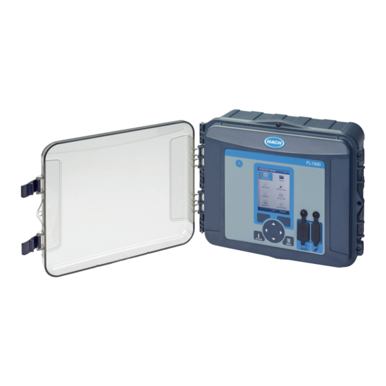
Figure 3 Product components 1 FL1500 flow logger 3 AC power cable with country-specific connector 2 Communications cable, USB A to B Installation D A N G E R Multiple hazards. Only qualified personnel must conduct the tasks described in this section of the document. - Page 11 Figure 4 Mounting dimensions English 9...
- Page 12 Figure 5 Mounting options 1 Horizontal wall, Unistrut or pipe mount 2 Vertical wall, Unistrut or pipe mount The instrument is supplied with the brackets in the horizontal position. To change to the vertical position, refer to the illustrated steps that follow. Use the pipe mounting kit for pipe installations.
-
Page 13: Electrical Installation
Electrical installation D A N G E R Electrocution hazard. Always remove power to the instrument before making electrical connections. Do not connect AC power directly to a DC powered instrument. If this equipment is used outdoors or in potentially wet locations, a Ground Fault Circuit Interrupt (GFCI/GFI) device must be used for connecting the equipment to its main power source. -
Page 14: Open The Access Door
Open the access door Open the access door to access the wiring connections. Refer to Figure Figure 7 Open the access door 1 High-voltage barrier—Remove only during power and relay installation. Wiring information D A N G E R Electrocution hazard. In order to maintain the NEMA/IP environmental ratings of the enclosure, use only conduit fittings and cable glands rated for at least NEMA 4X/IP66 to route cables in to the instrument. -
Page 15: Connect To Power
Connect to power The instrument can connect to an AC or a DC power source. When connected to AC power, an optional external backup battery can supply power if the AC power stops. Connect to AC power W A R N I N G Electrical shock and fire hazards. - Page 16 Figure 8 AC power connections Table 1 AC wiring information (AC models only) Connection Color—North America Color—EU, UK, AU Hot (L) Black Brown Neutral (N) White Blue Protective earth ground (G) Green Green with yellow stripe Connect a backup battery W A R N I N G Explosion and fire hazard.
-
Page 17: Connect To Dc Power
Install the battery near the instrument with the backup battery mounting bracket. Refer to the documentation supplied with the mounting bracket. Use a backup battery 3-pin half cable to connect the backup battery to the instrument. Refer to Figure 9 Table 2 to connect the backup battery to the DC terminal block. -
Page 18: Connect To Sensors
Figure 10 Connect to DC power Table 3 DC wiring information (DC models only) Connection Typical color 12 VDC (+) 12 VDC return (–) Black Connect to sensors Connect one or more sensors to the instrument to monitor the measurement data and calibrate the sensor. - Page 19 Figure 11 Sensor connections 1 Sensor port 1 4 Sensor port 4 (advanced model only) 2 Sensor port 2 5 Ring terminal for shield wires 3 Sensor port 3 (advanced model only) 6 Ground stud for shield wires (2x) Table 4 Sensor wiring Signal US9000 BL9000...
-
Page 20: Installation For Flo-Dar Or Flo-Tote Sensors
Table 4 Sensor wiring (continued) Signal US9000 BL9000 Flo-Dar Junction box AV9000S Flo-Tote 3 for US9000 2 V – Blue Black Green Green Green Black 1 SRQ — — Blue — — — Installation for Flo-Dar or Flo-Tote sensors Install the air reference tube and external desiccant to make sure that the pressure transducer in the sensor operates correctly. -
Page 21: Connect To Optional Devices
Connect to optional devices Refer to the steps that follow to connect the optional devices from the manufacturer. 1. Remove the power to the instrument. 2. Open the access door. Refer to Open the access door on page 12. 3. Put the cable through a strain relief fitting. 4. - Page 22 Figure 13 Optional device connections (advanced model shown) 1 RS485 6 Sampler (AS950 sampler is recommended) 2 Rain gauge 7 IO9004 module 3 Digital outputs (2x) 8 Analog input 4 Digital inputs (2x) 9 Analog outputs (3x) 5 Totalizer, mechanical Table 5 AS950 sampler wiring (auxiliary half cable 8528500/8528501) Connection Color...
- Page 23 Table 5 AS950 sampler wiring (auxiliary half cable 8528500/8528501) (continued) Connection Color Signal Description BLK INHIB Black Inhibit/Start Auxiliary control input—Start a sampler after the sampling program on another sampler ends. As an alternative, start a sampler when a trigger condition occurs. For example, when a high or low pH condition occurs, the sampling program starts.
-
Page 24: Connect To The Relays
Connect to the relays D A N G E R Electrocution hazard. Do not mix high and low voltage. Make sure that the relay connections are all high voltage AC or all low voltage AC. W A R N I N G Fire hazard. -
Page 25: Connect To The Inputs And Outputs
Table 9 Relay wiring information Connection Signal Normally open Common Normally closed Connect to the inputs and outputs Connect a user-supplied device such as a PLC, recorder or third-party sensor to the analog input, analog output, digital input or digital output terminal blocks. Use a minimum wire gauge of 24 AWG. Make sure to obey the requirements for the input or output connection in Specifications on page 3. - Page 26 Figure 15 FL1500-powered loop 1 Analog output 2 External device Figure 16 Externally-powered loop 1 Analog output 2 External power supply 3 External device Table 12 Digital input wiring information Connection Signal Negative for THRESHOLD THRESHOLD 25 VDC maximum Negative (–)
-
Page 27: Connect To An Rs485 Network
Connect to an RS485 network Connect to an RS485 network for remote communication. 1. Remove the power to the instrument. 2. Open the access door. Refer to Open the access door on page 12. 3. Put the cable through a strain relief fitting. 4. -
Page 28: Show The Data As A Slideshow
• Channels Logging—Shows the number of logged channels. Select Channels Logging to see the measurement data for the logged channels. Use the right arrow to scroll through the measurement data for all channels. • Active Channel—Shows the active alarms. Select Active Channel to see the channel and system alarms. -
Page 29: Status Indicators
Table 15 Main menu options (continued) Option Description Option Description Calibrates the installed sensors. Shows the measurement data (the data log). Calibration Review Data Shows the status screen, event Shows the instrument details (e.g., log, alarm log, sensor data and serial number). -
Page 30: Set Up The Sensors-Setup Wizard
Push the UP and DOWN arrows to change the value. Push the LEFT and RIGHT arrows to move the cursor. Option Description About Shows the instrument description, serial number and firmware version. Status Display Sets the display to show the measurement screens in a slideshow format. Refer to Setup (slideshow) Show the data as a slideshow on page 26. -
Page 31: Flo-Dar Setup
Flo-Dar setup Pre-requisites: Install the sensor in the process and the sensor cable in the logger before this task is started. Use the Sensor Setup menu to configure the Flo-Dar sensor for flow measurements. To use the factory-set options for the sensor, select Restore Defaults in the Sensor Setup menu. 1. -
Page 32: Av9000S Setup
4. Select Setup Port [1] (sensor name). 5. Complete the options in the Basic Settings menu. Option Description Level Calibration Sets the instrument reading for level to the same value that is measured in the flow channel. Enter the vertical distance from the bottom of the flow channel to the top of the liquid. -
Page 33: Us9000 Setup
Option Description Level Calibration Sets the instrument reading for level to the same value that is measured in the flow channel. Enter the vertical distance from the bottom of the flow channel to the top of the liquid. Sensor Direction Selects the installation direction of the sensor. Select Reversed if the sensor is installed in the reverse direction. -
Page 34: Ph Sensor Setup
1. Select Sensor Setup>Change port assignments. 2. Select the number of the sensor connector in the instrument where the sensor wires are installed. 3. Select the sensor name. Select OK. The sensor name shows next to the selected port number. 4. -
Page 35: Calibrate The Sensors
4. Select Setup Port [1] (sensor name). 5. Complete the options in the Basic Settings menu. Option Description AC Frequency Selects the power line frequency to get the best noise rejection. Options: 50 or 60 Hz (default). Calibrate the sensors Calibrate the sensors during sensor setup and at regular intervals. - Page 36 Alarms are available for the system and for the channels. The channel alarms are setpoint alarms for the recorded measurements (channels), such as the pH, level and power supply voltage. The system alarms are for sensor timeout errors, power issues or digital inputs (digital inputs are available on advanced model only).
-
Page 37: Configure The Software Totalizer
Figure 18 High setpoint example 1 Measurement value 3 Setpoint trigger off 5 Setpoint value 2 Setpoint trigger on 4 Deadband 6 Time 5. Add a system alarm as follows: a. Select System Alarms>Add New Alarm>[Select System Alarm]. b. Select the type of alarm. c. -
Page 38: Configure The Mechanical Totalizer
6. To set the totalizer to zero for a configured flow channel, select Reset. Note: If channels are added to or removed from a program, the instrument erases all data from all channels and totalizers (resettable and non-resettable). Make sure to download the data from the logger to a safe location before the program is changed. -
Page 39: Configure Flow Pacing For Connected Samplers
3. Select an option: Option Description Internal I/O Configures the inputs, outputs and relays in the instrument. External I/O Configures the inputs, outputs and relays in a connected IO9004 module. Select External I/O>IO9004>Enable. 4. Select the input or output option: Option Description Analog inputs... -
Page 40: Save Data To A Usb Stick
FSDATA Destop format. 5. Select OK and remove the USB memory stick. The instrument makes an FL1500 folder on the USB memory stick. The data files go in a new subfolder each time the instrument sends data. Import or export the instrument settings N O T I C E When the import option is used, all the user settings in the instrument are replaced with the imported settings. -
Page 41: Maintenance
Maintenance D A N G E R Multiple hazards. Only qualified personnel must conduct the tasks described in this section of the document. Maintenance schedule Table 17 shows the recommended schedule of maintenance tasks. Facility requirements and operating conditions may increase the frequency of some tasks. Table 17 Maintenance schedule Task As necessary... -
Page 42: Replace The Internal Desiccant
Figure 19 Fuse location 1 DC fuse 3 Relay fuse 2 AC fuse Replace the internal desiccant The desiccant absorbs moisture to prevent component damage. The color of new desiccant is orange. When the desiccant is full of moisture, the color of the desiccant changes to green. Replace the desiccant when the color of the desiccant is green. -
Page 43: Remove The Cover (Optional)
Figure 20 Replace the desiccant Remove the cover (optional) The instrument cover can be removed temporarily for maintenance tasks. Make sure to keep the cover on during operation to prevent direct exposure to environmental conditions. Refer to the illustrated steps that follow. English 41... -
Page 44: Troubleshooting
Troubleshooting Use the diagnostic menu to see the recorded events and alarms and to find the possible source of a problem. 1. Push MENU. 2. Select Diagnostics. 3. Select an option: Option Description Status Gives the number of logged channels, the active channel, totalizer info, and sensor port connections. - Page 45 Accessories Description Item no. Backup battery, 12 VDC lead acid 8757400 Backup battery/power supply mounting bracket 8315500 Backup battery power supply 8754500XX Backup battery 3-pin half cable 8307900 Bracket for AV9000S, BL9000 bubbler 8309300 Cable, half, to AS950 sampler, 2.7 m (9 ft) 8528500 Cable, half, to AS950 sampler, 7.6 m (25 ft) 8528501...
- Page 46 44 English...
- Page 48 *DOC343.53.80573* HACH COMPANY World Headquarters P.O. Box 389, Loveland, CO 80539-0389 U.S.A. Tel. (970) 669-3050 (800) 368-2723 (U.S.A. only) U.S.A. – orders@hach.com International – international@hach.com flowtechsupport@hach.com www.hachflow.com © Hach Company/Hach Lange GmbH, 2017. All rights reserved.
Need help?
Do you have a question about the FL1500 and is the answer not in the manual?
Questions and answers