Table of Contents
Advertisement
Quick Links
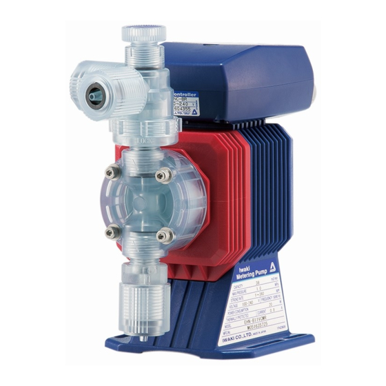
Iwaki
Electromagnetic Metering Pump
EHN-YN
Instruction manual
Thank you for choosing our product.
Please read through this instruction manual before use.
This instruction manual describes important precautions and instruc-
tions for the product. Always keep it on hand for quick reference.
©2010 IWAKI CO., LTD.
Advertisement
Table of Contents

Related Manuals for IWAKI EHN-YN


Summary of Contents for IWAKI EHN-YN
- Page 1 Instruction manual Thank you for choosing our product. Please read through this instruction manual before use. This instruction manual describes important precautions and instruc- tions for the product. Always keep it on hand for quick reference. ©2010 IWAKI CO., LTD.
-
Page 2: Order Confirmation
Order confirmation Open the package and check that the product conforms to your order. If any problem or inconsistency is found, immediately contact your distributor. a. Check if the delivery is correct. Check the nameplate to see if the information such as model codes, discharge capacity, discharge pressure and power voltage are as ordered. -
Page 3: Table Of Contents
Contents Order confirmation ............................2 Safety instructions ..............6 Warnings ................................ 7 Cautions ................................. 8 Precautions for use ............................ 10 Overview ...................12 Introduction ..............................12 Pump structure & Operating principle ...................... 12 Features ..............................13 Operational function ........................... 13 Manual mode ............................13 EXT mode .............................. - Page 4 Operation ................. 33 Before operation ............................33 Points to be checked ..........................33 Retightening of pump head fixing bolts ....................33 Use of a hexagon wrench instead of a torque wrench ................ 33 Degassing ..............................34 EHN-B/-C 11/16/21 VC/VH/PC/PH/PP/SH ..................34 EHN-B/-C 11/21 FC and EHN-B/-C 31/36 VC/VH/PC/PH/PP/FC ............36 Flow rate adjustment ..........................
- Page 5 Discharge valve set disassembly/assembly ..................58 Suction valve set disassembly/assembly .................... 60 Air vent valve set replacement (SH type) ....................61 Air vent valve set replacement (NAE type)....................62 Flow checker replacement (FCM/XFCM) ....................62 Diaphragm replacement ...........................64 Exploded view ............................. 66 Pump head, Drive unit &...
-
Page 6: Safety Instructions
Safety instructions Read through this section before use. This section describes important information for you to prevent personal injury or property damage. ■ Symbols In this instruction manual, the degree of risk caused by incorrect use noted with the following symbols. -
Page 7: Warnings
WARNINGS Turn off power before service Risk of electrical shock. Be sure to turn off power to stop the pump and related devices before service is performed. Electrical shock Stop operation If you notice any abnormal or dangerous conditions, suspend operation Requirement immediately and inspect/solve problems. -
Page 8: Cautions
CAUTIONS Qualified personnel only The pump should be handled or operated by qualified personnel with a full understanding of the pump. Any person not familiar with the product Requirement should not take part in the operation or management of the pump. Use specified power only Do not apply power other than that specified on the nameplate. - Page 9 Do not use the pump in a wet location The pump is not waterproof. Use of the pump in wet or extremely humid locations could lead to electric shock or short circuit. Prohibited Grounding Risk of electrical shock! Always properly ground the pump. Conform to lo- Grounding cal electric codes.
-
Page 10: Precautions For Use
Precautions for use • Electrical work should be performed by a qualified electrician. Otherwise, personal injury or property damage may result. Caution • Do not install the pump: –In a flammable atmosphere. –In a dusty/humid place. –In direct sunlight or wind & rain. –Where ambient temperature can exceed 40ºC or falls below 0ºC. - Page 11 • The pump has a rating of IP65, but is not waterproof. Do not operate the pump while wet with solution or water. Failure or injury may result. Immedi- ately dry off the pump if it gets wet. Caution • Do not close discharge line during operation. Solution may leak or tub- ing may break.
-
Page 12: Overview
Overview Pump characteristics, features and part names are described in this sec- tion. Introduction Pump structure & Operating principle The EHN series is a diaphragm metering pump which consists of a pump head, drive unit and control unit. A diaphragm is directly driven by electromagnetic force. Principle of operation Electromagnetic force and spring force make reciprocating motion. -
Page 13: Features
The pump starts to run at a full speed (360spm) once a flow checker detects gas lock in the pump head. * The pump stops when having failed to resolve gas lock. * The XFCM type flow checker can not be connected to the EHN-YN. Connect it to an external controller to make feed- back control. -
Page 14: Ext Mode
EXT mode ■ Proportional control (Analogue control : See page 42) The pump increases/decreases a stroke rate in the range of 0-360spm in proportion to 0-20mA. Setting two points can draw a straight line. Depending on the position of the two points, 0spm may not come at 0mA or a stroke rate may go over 360spm (The maximum stroke rate is 360spm and the pump does not exceed that rate.). -
Page 15: Divisor Programming
■ Divisor programming (Digital control : See page 46) The pump operation by the external signal. Program a divisor before operation. 1-999 pulse signals can be al- located to make one shot. * The pump can not run over a MAN speed even if a divisor is set to run the pump beyond that speed. *The pump makes one shot per pulse when a divisor is programmed to 1. -
Page 16: Priming Function
■ Priming function (See page 49) The pump runs at the maximum stroke rate while both the UP and DOWN keys are pressed. Use this function for priming or degassing. Press Press ▲+▼ keys Pump operation 1 2 3 4 5 1 2 3 ■... -
Page 17: Part Names
Part names Pump Gasket Covers a control unit mounting screw. Adjusting screw Used for opening the air vent port. Control unit Used for the start/stop of the pump and stroke rate adjust- ment/programming. Air vent port Always connect a tube. Be sure to return the tube end to a supply tank or a container. -
Page 18: Operation Panel
Operation panel STOP OVER Lights as the pump stops Lights when the pump is set running by the STOP signal. to run over 360spm through an EXT mode. Lights during EXT operation. WAIT Set point 1 and 2 Lights during a wait state. Lights when set point 1 and 2 are being set for analogue control. -
Page 19: Basic Displays
■ Basic displays Display States Manual mode. The pump is running at 360spm. A waiting state. "WAIT" indication appears. Numerical value shows a MAN speed. EXT mode with a multiplier 5. The pump is making five shots per signal. EXT mode with a divisor 5. The pump is making one short per 5-signal. -
Page 20: Alarm Displays
■ Alarm displays Display States "EXT" and "OVER" indications appear when the pump is set to run over 360spm by current signal input under analogue control, however, the pump does not exceed that maximum rate at any current value. "EXT" and "OVER" indications appear when the pump under digital control receives an external signal before the programmed shots per signal is completed. -
Page 21: Auto Restoration Displays (Fcm Type)
■ Auto restoration displays (FCM type) Display States Pre-Alarm time is being set. Alarm time is being set. Return time is being set. Alarm out is being set. The pump is running at full speed after the detection of air lock. The pump has stopped after failing to remove air lock. -
Page 22: Identification Codes
Identification codes Each code represents the following information. Pump EHN - B 11 VC 1 YN - - FCM a. Series name EHN : Multivoltage electromagnetic metering pump b. Drive unit (Average power consumption) B : 20W C : 24W c. -
Page 23: Control Unit
e. Tube connection bore Tube connection bore Tube type Remarks ø4×ø9 PVC braided tube or EVA tube ø4×ø6 Teflon or polyethylene tube EHN-11/-16/-21 FC types ø6×ø8 Teflon or polyethylene tube ø8×ø13 PVC braided tube or EVA tube ø9×ø12 Teflon or polyethylene tube ø10×ø12 Teflon tube EHN-31/-36 FC types... -
Page 24: Installation
Installation This section describes the installation of the pump, piping and wiring. Read through this section before work. Points to be observed Observe the following points when installing the pump. • Be sure to turn off power to stop the pump and related devices before service is per- formed. -
Page 25: Plumbing
Plumbing Connect tubes to the pump and install a check valve. Before operation Tube end (Side view) • Cut the tube ends flat. Necessary tools • Adjustable wrench or spanner. Tube connection ■ VC/VH/PC/PH/PP/FC/SH types a. Pass a tube into the fitting nut and slide it down to the hose adapter as far as Tube it will go. -
Page 26: Sh Type
Air vent port Determine an air vent port direction. The air vent port can rotate 90 degrees. a. Turn the lock nut anticlockwise. Air vent body A b. Adjust the direction of the air vent port. Lock nut c. Hand-tighten the lock nut, holding the air vent body A. d. -
Page 27: Check Valve Mounting
Check valve mounting Install an optional check valve to the EHN-YN (or a back pressure valve to the FC type) for the prevention of a back flow, siphon and overfeeding. In the following cases be sure to install the check valve. - Page 28 Mount a check valve at the discharge tube end. * The CA check valve and the BVC back pressure valve have R1/2 and R3/8 thread connections as well as a tube connection. Cut off and adjust the connection length to fit the check valves into tubing. CA check valve BVC back pressure valve (for FC type) R1/2...
-
Page 29: Wiring
Wiring Wiring for power voltage, earthing and external signals. Points to be observed Observe the following points during wiring work. • Electrical work should be performed by a qualified electrician. Always observe applica- ble codes or regulations. • Observe the rated voltage range, or the electrical circuit in the control unit may fail. •... -
Page 30: Signal Wire Connection
Surge voltage The electronic circuit in the control unit may fail due to surge voltage. Do not place the pump close to a high power device of 200V or more which may generate large surge volt- age. Otherwise, take any of the following measures. •... - Page 31 NOTE • Do not lay on these signal cables in parallel with a power cable. Otherwise noise is generated through the cables due to induction effect and it results in malfunction or failure. • The following products are the recommended SSRs (Solid State Relays) for signal input. Any other SSRs may cause malfunction.
- Page 32 Connect the external signal cable. a. Use a precision screwdriver to connect signal wires to the signal- line terminal block. b. Attach the power-line and signal-line terminal blocks to the PCB. c. Adjust the slackness of the signal cable, pulling it out. d.
-
Page 33: Operation
Operation This section describes pump operation and programming. Run the pump after pipework and wiring is completed. Before operation Check a flow rate, tubing and wiring. And then perform degassing and flow rate adjustment before starting operation. Points to be checked Before operation, check if... -
Page 34: Degassing
Degassing The gas needs to be expelled from the pump and tubing by degassing. Normal performance can not be ob- tained with gas in the pump. Conduct degassing in the following cases. • When the pump starts to run for the first time. •... - Page 35 Adjusting screw Rotate the adjusting screw two revolutions anticlockwise to open the air vent port (1/4 revolution for the SH type). * Do not rotate the screw three revolutions. Otherwise, liquid may come out from the air vent port. * Switch the screw to OPEN position for the SH type. Push the start/stop key and run the pump for more than ten minutes for degassing.
-
Page 36: Ehn-B/-C 11/21 Fc And Ehn-B/-C 31/36 Vc/Vh/Pc/Ph/Pp/Fc
■ EHN-B/-C 11/21 FC and EHN-B/-C 31/36 VC/VH/PC/PH/PP/FC The air vent port is not provided to the EHN-B/-C 11/12 FC type and all the EHN-B/-C 31/36 types. Install an air vent valve on a discharge line for degassing. See page 26 for detail. Follow the procedure below to conduct degassing if the air vent valve is not available. -
Page 37: Flow Rate Adjustment
Flow rate adjustment A flow rate can be adjusted by adjusting a stroke rate and stroke length. The stroke rate is indicated in spm (stroke per minutes). Stroke rate adjustment is a main way to adjust a flow rate. Stroke length is the moving distance of the plunger. A flow rate per shot can be controlled by changing stoke length. -
Page 38: Stroke Rate Adjustment
■ Stroke rate adjustment A stroke rate can be set by keypad operation from 1 to 360spm. The relation between a flow rate* and a stroke rate is shown as below. Fixed stroke length * The flow rate described on the nameplate is at 100%. -
Page 39: Stroke Length Adjustment
■ Stroke length adjustment A stroke length can be adjusted when the moving distance of the plunger is changed by the stroke length ad- justing knob. The stroke length adjustment range is 50-100% for the B type, 40-100% for C type. The relation between a flow rate* and a stroke length is shown as below. -
Page 40: Operation Programming
Operation programming Operation at each mode is individually set and controlled by keypad operation. Select a prop- er mode to make optimal operation. Minimum incre- Mode Parameters Default Setting ranges ment/decrement Manual Stroke rate*¹ 1-360 1*² Dig/Ana selection Digital/Analog dIG (Digital) dIG (digital)/ANA(Analog) Multiplier (Digital) 1-999... -
Page 41: Programming Flow
Programming flow STOP ON/OFF selection Buffer ON/OFF selection Buffer ON (Divisor) Buffer OFF (Multiplier) EXT mode selection Digital control (Divisor) Digital control (Multiplier) Power ON Buffer OFF (Divisor) Buffer ON (Multiplier) Wait state Analog control Digital/Analog selection WAIT Digital control Analog control Manual operation WAIT... -
Page 42: Operation
Operation Read this section before operation. Manual operation Run or stop the pump by keypad operation. Supply the rated power voltage to the pump. The ON LED lights and a previous mode at the last shutoff returns. * The pump waits in the manual mode when turning on power with a default setting. Push the start/stop key to return to the wait state. - Page 43 Select "ANA". Scroll through "dIG" and "ANA" selection by the UP and DOWN keys. Push the start/stop key to return to the wait state. Push the DOWN key while pressing the EXT key to program the analog control. Program the SET1 & 2. Use the UP and DOWN keys to enter a current value at SET 1.
-
Page 44: Digital Control Programming
■ Digital control programming The pump operation is controlled by the external (pulse) signal. Set a multiplier or a divisor before operation. NOTE • The pump runs at a MAN speed in the digital control. If a MAN speed is set to 200spm, the pump does not run over the speed even though a multiplier is set to run the pump at 360spm. - Page 45 Push the EXT key to call up the buffer ON/OFF selection. Scroll through "X-ON" and "X-OFF" by the UP and DOWN keys. Buffer ON/OFF selection Buffer OFF (Divisor) Buffer ON (Divisor) Buffer ON (Multiplier) Buffer OFF (Multiplier) Push the start/stop key to return to the wait state. Push the DOWN key while pressing the EXT.
- Page 46 Divisor programming Program the number of signals per shot to control the pump. The number of signals can be programmed from 1 to 999. NOTE • If a divisor is programmed to 1 so as to make one shot per pulse and the input interval of the external signal is close to a MAN speed (but not exactly in synchronization), irregular operation may occur.
- Page 47 Push the EXT key to call up the buffer ON/OFF selection. Scroll through "/-ON" and "/-OFF" by the UP and DOWN keys. Buffer ON/OFF selection Buffer OFF (Divisor) Buffer ON (Divisor) Buffer ON (Multiplier) Buffer OFF (Multiplier) Push the start/stop key to return to the wait state. Push the DOWN key while pressing the EXT key.
-
Page 48: Stop Function
STOP function The start/stop of the pump operation can be controlled by the external stop signal. • Operation stop at the stop signal input: "M-OF" The pump stops while receiving the stop signal. • Operation resumption at the stop signal input: "M-ON" The pump runs while receiving the stop signal. -
Page 49: Keypad Lock
Keypad lock Keypad lock can be active for the prevention of erroneous key operation. NOTE • Any key operation is not acceptable when the keypad lock is active. In an emergency, turn off the main power to stop operation. In this case, keypad lock state is recalled when the pump is turned on. ■... -
Page 50: Auto Restoration (Fcm Type)
Auto restoration (FCM type) NOTE • A long period of dry running damages the pump. Do not set the Alarm time over 30 minutes for the pump not to continue to run dry. ■ Auto restoration programming Push the start/stop key to return to the wait state. "WAIT"... - Page 51 Push the EXT key. Use the UP or DOWN key to adjust Return time. • The time increases/decreases in the range of 1-60 minutes/seconds as pushing the UP/DOWN keys. • Press and hold either key for three seconds for quick change. Quick change stops at 60 min/sec or "REOF".
- Page 52 Use the UP or DOWN key to set behaviour at each item. The pump keeps outputting an alarm signal during the Pre-Alarm time and Alarm time and when the pump has failed to remove gas lock and stopped running. The pump keeps outputting an alarm signal during the Pre-Alarm time and Alarm time.
-
Page 53: Auto Restoration (Fcm Type)
Error codes ■ Reset of "PErr" (Full speed operation to resolve air lock) Push the start/stop key while pressing the EXT key. The pump resumes normal operation. ■ Reset of "FLOW" (Suspended operation after failing to resolve gas lock) Push the start/stop key. The pump waits in the manual mode. -
Page 54: Maintenance
Maintenance This section describes troubleshooting, maintenance, wear part replace- ment, exploded views and specifications. Points to be observed Observe the following points during maintenance work. • Follow instructions in this manual for replacement of wear parts. Do not disassemble the pump beyond the extent of the instructions. - Page 55 States Possible causes Solutions Valve gaskets are not installed. • Install valve gaskets. Liquid can not be pumped up. Foreign matters are stuck in the pump • Dismantle, inspect and clean the valves. head valves. Replace as necessary. A ball valve is stuck on a valve seat. •...
-
Page 56: Inspection
Inspection Perform daily and periodic inspection to keep pump performance and safety. Daily inspection Check the following points. Upon sensing abnormality, stop operation immediately and remove problems ac- cording to "Troubleshooting". When wear parts come to the life limit, replace them with new ones. Contact your distributor for detail. States Points to be checked How to check... -
Page 57: Wear Part Replacement
Wear part replacement To run the pump for a long period, wear parts need to be replaced periodically. It is recommended that the following parts are always stocked for immediate replacement. Contact your nearest distributor for detail. Precautions • Solution in the discharge line may be under pressure. Release the pressure from the dis- charge line before disconnecting plumbing or disassembly of the pump to avoid solution spray. -
Page 58: Before Replacement
Before replacement First release pressure from the pump head and discharge line. Stop pump operation. Rotate the adjusting screw or open an air vent line to release pressure. NOTE • Do not rotate the adjusting screw anticlockwise three revolutions or more from the closed position. Otherwise, liquid may come out from the adjusting screw. - Page 59 Remove the air vent body B by the 17mm box wrench Air vent body B Pull out the valve set by a pair of tweezers. Place a new valve set into the pump head and screw the air Air vent body B vent body B through the lock nut.
-
Page 60: Suction Valve Set Disassembly/Assembly
Place a new valve set into the pump head. Hand-tighten the fitting into the pump head as far as it will go. Retighten it further 90 degrees with an adjustable wrench or a spanner. Fitting * Be careful not to misarrange the valve set or misplace upside down. Other- wise, leakage or flow rate reduction may result. -
Page 61: Air Vent Valve Set Replacement (Sh Type)
Air vent valve set replacement (SH type) Rotate the adjusting bolt anticlockwise until it comes off. Adjusting screw Rotate the seal nut clockwise by an adjustable wrench or a spanner until it comes off. * Seal nut threads are left-handed. Seal nut Pull out the spring, seal ring, spacer and valve ball by a pair of tweezers. -
Page 62: Air Vent Valve Set Replacement (Nae Type)
Air vent valve set replacement (NAE type) Loosen the fitting nut and remove an air bleed tube. Air bleed tube * Be careful not to get wet with a residual chemical AUTO air vent port Loosen and remove the fitting. Fitting Take the air vent valve set out of the fitting adapter. - Page 63 Remove the air vent body B by an adjustable wrench or a spanner. Lock nut Air vent body B Pull out the valve set by a pair of tweezers. Replace the valve set into the air vent body B of another flow check- er.
-
Page 64: Diaphragm Replacement
Diaphragm replacement Necessary tools • Adjustable wrench or spanner • Hexagon wrench • Torque wrench NOTE Pay attention not to loose diaphragm spacers. Always apply a proper number of diaphragm spacers. 0 or a few diaphragm spacers are inserted between the retainer and plunger for the adjustment of diaphragm location. Note that the number of diaphragm spacers varies with pump model. - Page 65 NOTE • Fit the retainer to the diaphragm with its round edge to the diaphragm. Mating parts • Check that the bracket spacer is in place. Refit the bracket spacer into the Bracket bracket, combining mating parts as necessary. Bracket spacer Screw the diaphragm into the plunger as far as it will go.
-
Page 66: Exploded View
Exploded view Pump head, Drive unit & Control unit Do not dismantle the pump beyond the extent shown in the diagram below. EHN-B/-C 11/16/21 EHN-B/-C 31/36 EHN-C 36 Air vent Air vent Cable gasket Cable nut Terminal case Diaphragm spacer Gasket Valve set* Retainer... -
Page 67: Pump Head
Pump head ■ EHN-B11/-B16/-B21/-C16/-C21 VC/VH/PC/PH Part names # of parts Pump head Fitting Fitting nut Air vent body B Lock nut Diaphragm Retainer Air vent body A Valve guide Valve seat Valve Valve gasket O ring Diaphragm spacer Hex socket cap bolt [PW•SW] Adjusting screw O ring O ring... -
Page 68: Ehn-B11/-B16/-B21/-B31/-C16/-C21/-C31/-C36 Pp
■ EHN-B11/-B16/-B21/-B31/-C16/-C21/-C31/-C36 PP Part names # of parts Pump head Fitting 1(2) Fitting nut 3(2) Air vent body B 1(0) Lock nut 1(0) Diaphragm Retainer Air vent body A 1(0) Valve guide Valve seat Valve Valve gasket O ring Diaphragm spacer Hex socket cap bolt [PW•SW] Adjusting screw 1(0) -
Page 69: Ehn-B11/-B16/-B21/-B31/-C16/-C21/-C31/-C36 Sh
■ EHN-B11/-B16/-B21/-B31/-C16/-C21/-C31/-C36 SH Part names # of parts Pump head Fitting Diaphragm Retainer Valve guide Valve seat Valve Valve gasket B Diaphragm spacer Hex socket cap bolt Valve gasket A Seal nut Adjusting bolt Spring Seal ring Valve ball Tube connector Spacer * The number of diaphragm spacers varies with pump model. -
Page 70: Ehnb-11/-B16/-B21/-B31/-C16/-C21/-C31/-C36 -Fcm/-Xfcm
■ EHNB-11/-B16/-B21/-B31/-C16/-C21/-C31/-C36 -FCM/-XFCM Part names # of parts Pump head Fitting nut Air vent body B Lock nut Diaphragm Retainer Air vent body A Valve guide Valve seat Valve Valve gasket O ring Diaphragm spacer Hex socket cap bolt [PW•SW] Adjusting screw O ring O ring... -
Page 71: Specifications/Outer Dimensions
Specifications/Outer dimensions Specifications Information in this section is subject to change without notice. ■ Pump VC/VH/PC/PH/PP Discharge Stroke length Power Current Flow rate Stroke rate Connection Weight Model code pressure con. value ml/min EHN-B11 EHN-B16 ø4×ø9 0.5-1.0 (50-100) EHN-B21 EHN-B31 ø8×ø13 1-360 EHN-C16... -
Page 72: Control Unit
Power voltage* 100-240VAC 50/60Hz *1 The maximum applied voltage from the EHN-YN to an external contact is 12V at 5mA. When using a mechanical relay, the minimum application load should be 5mA or below. *2 When the pump receives the external pulse signal during operation for the set number of shots per signal, the received signal is stored up to 255 pulses. -
Page 73: Accessories
Accessories Connection Set pressure Applicable pump mod- Wet end Model code bore Wet ends codes CA-1VC-4 EHN-B11/-B16/-B21 ø4×ø9 EHN-C16/-C21 CA-1VE-4 0.17 CA-2VC-8 EHN-C31 CA-2VE-8 ø8×ø13 CA-2VCL-8 EHN-B31 0.05 EHN-C36 CA-2VEL-8 CA-1V-4 PC/PP EHN-B11/-B16/-B21 ø4×ø9 EHN-C16/-C21 CA-1E-4 0.17 CA-2V-8 PC/PP GFRPP EHN-C31 CA-2E-8 ø8×ø13... -
Page 74: Outer Dimensions
Outer dimensions ■ EHN-B11/-B16/-B21 VC/VH/PC/PH/PP (209) (37) (21) (25) 81.5 7 16 10 ■ EHN-B31 VC/VH/PC/PH/PP (190) (16) (21) 81.5 (27) 7 16 10 Specifications/Outer dimensions... -
Page 75: Ehn-C16/-C21 Vc/Vh/Pc/Ph/Pp
■ EHN-C16/-C21 VC/VH/PC/PH/PP (227) (37) (18) (27) ■ EHN-C31/-C36 VC/VH/PC/PH/PP (208) (16) (18) (29) Specifications/Outer dimensions... -
Page 76: Ehn-B11/-B21 Fc
■ EHN-B11/-B21 FC (184) (12) (21) (25) 81.5 7 16 10 ■ EHN-C21 FC (202) (12) (18) (27) Specifications/Outer dimensions... -
Page 77: Ehn-C31/-C36 Fc
■ EHN-C31/-C36 FC (208) (16) (18) (29) Specifications/Outer dimensions... -
Page 78: Ehn-B11/-B21 Sh
■ EHN-B11/-B21 SH (205) (34) Rc1/4 OD φ 4 Rc1/4 (21) (24) 81.5 7 16 10 ■ EHN-C21 SH (226) (37) Rc1/4 OD φ 4 Rc1/4 (18) (26) Specifications/Outer dimensions... -
Page 79: Ehn-C31 Sh
■ EHN-C31 SH (226) (35) Rc1/4 OD φ 4 Rc1/4 (18) (28) ■ EHN-C36 SH (225) (34) Rc1/4 OD φ 4 Rc1/4 (18) (28) Specifications/Outer dimensions... -
Page 80: Ehn-B11/-B16-Nae
■ EHN-B11/-B16-NAE (209) (37) AIR(AUTO) (21) (25) 81.5 7 16 10 ■ EHN-C16/-C21-NAE (227) (37) AIR(AUTO) (18) (27) Specifications/Outer dimensions... -
Page 81: Ehn-B11/-B16-/B21-Fcm/-Xfcm
■ EHN-B11/-B16-/B21-FCM/-XFCM (209) (37) (21) 81.5 (25) (37) 7 16 10 ■ EHN-C16/-C21-FCM/-XFCM (227) (37) OUT AIR (18) (27) (37) Specifications/Outer dimensions... - Page 84 IWAKI Norge AS TEL : (43)23 38 49 00 FAX : 23 38 49 01 China IWAKI Pumps (Guandong) Co., Ltd. TEL : (86)750 3866228 FAX : 750 3866278 Singapore IWAKI Singapore Pte. Ltd. TEL : (65)6316 2028 FAX : 6316 3221 China GFTZ IWAKI Engineering &...
Need help?
Do you have a question about the EHN-YN and is the answer not in the manual?
Questions and answers