Table of Contents
Advertisement
Quick Links
Advertisement
Table of Contents

Subscribe to Our Youtube Channel
Related Manuals for Jireh STIX


Summary of Contents for Jireh STIX
- Page 1 STIX DX0022 Rev 01 Manual Flange Scanner...
- Page 2 SAFETY WARNINGS / PRECAUTIONS KEEP THIS MANUAL – DO NOT LOSE THIS MANUAL IS PART OF THE STIX AND MUST BE RETAINED FOR THE LIFE OF THE PRODUCT. PASS ON TO SUBSEQUENT OWNERS. Ensure any amendments are incorporated with this document.
-
Page 3: Table Of Contents
TABLE OF CONTENTS Identification Chapter 1.1. Product Brand 1.2. Manufacturer Product Specifications Chapter 2.1. Intended Use 2.1.1. Operating Limits 2.1.2. Operating environment 2.1.3. User 2.2. Unintended Use 2.3. Dimensions and Weight 2.4. Environmental Sealing 2.5. Performance Specifications Definitions Chapter 3.1. Definition of Symbols System Components Chapter 4.1. - Page 4 Maintenance Chapter Troubleshooting Chapter 8.1. Technical Support Spare Parts Chapter 9.1. Flange Scanner Components 9.1.1. Encoder Connector Type 9.2. STIX Kit Components 9.3. Probe Holder Components 9.3.1. Arm Style 9.3.2. Pivot Button Style 9.4. Variable Components 9.4.1. Frame Bars Disposal Chapter Limited Warranty Chapter...
- Page 5 PAGE iv of iv...
-
Page 6: Product Brand
Chapter 1 IDENTIFICATION 1.1. Product Brand This user manual applies to the STIX - Flange Scanner which is used for a variety of flange coupling inspection applications such as flange face corrosion. 1.2. Manufacturer DISTRIBUTOR: MANUFACTURER: Jireh Industries Ltd. 53158 Range Road 224... -
Page 7: Product Specifications
Chapter 2 PRODUCT SPECIFICATIONS 2.1. Intended Use The scanner’s primary purpose is to move an inspection tool over a cylindrical surface for inspection of flanges. The intended surface is to: be free of excess rust, scale, ferrous debris, ice, frost ►... -
Page 8: Unintended Use
11 in 29.8 cm 11.7 in Frame Weight: 2.4 kg 5.3 lb Encoder Cable Length 16.4 ft (Standard Kit) 2.4. Environmental Sealing Watertight (not submersible) (contact Jireh Industries Ltd. on page 1 for details) DX0022 Rev 01 PAGE 3 of 33... -
Page 9: Performance Specifications
2.5. Performance Specifications X-Axis Encoder Resolution: 9.05 counts/mm 230.0 counts/inch PAGE 4 of 33... -
Page 10: Definitions
Chapter 3 DEFINITIONS 3.1. Definition of Symbols Instructions to ‘look here’ or to ‘see this part’. Denotes movement. Instructing user to carry out action in a specified direction. Indicates alignment axis, can also indicate insertion or movement of parts. Alerts user that view has changed to a reverse angle. -
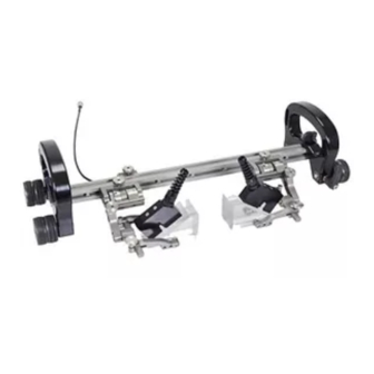
Page 11: System Components
- Spring-Loaded Encoder - Frame Bar with Ruler Fig. 2 Fig. 3 Fig. 4 DXA001- BGS053- BG0090- - Irrigation Kit - STIX Flange Scanner Case - Magnetic Wheel Fig. 5 Fig. 6 Fig. 7 CMG007 DXA002 BTS031 - 3/8 in Wrench... -
Page 12: Tools
Fig. 11 Fig. 12 The 3 mm hex driver is sufficient for all typical operations and adjustments (Fig. 11) of the STIX. The 3/8 in wrench is used to remove and install buttons on the probe (Fig. 12) holders. DX0022 Rev 01... -
Page 13: Flange Scanner Frame
4.3. Flange Scanner Frame - Loosen black wing knobs to loosen the flange scanner’s pivot Fig. 13 4.3.1. Articulated Side Frames To pivot the articulated side frames to accommodate various diameter sizes, follow these steps: Loosen the two black wing knobs on the sides of the articulated side frame (Fig. - Page 14 - Diameter indicator - Place on inspection surface Fig. 17 Fig. 15 Observe the diameter indicators to assist with setting the scanner to the correct diameter required (Fig. 17) Tighten the black wing knobs (Fig. 16) Place the scanner on the flange to be inspected (Fig.
-
Page 15: Probe Centre Spacing
4.3.2. Probe Centre Spacing Probe centre spacing is adjusted using these following steps: - Slide the articulated side frame along the frame bar to adjust probe spacing Fig. 18 The articulated side frame operates with a firm friction fit. Slide the one half of the articulated side frame along the frame bars to achieve the probe spacing required (Fig. - Page 16 - Set probe spacing and configure guides Fig. 19 When probe spacing as been completed , position the flange (Fig. 19) scanner guides as required (see Flange Scanner Guides on page 13) Probe spacing may also be achieved by placing the wedge in alternate pivot button holes of the probe holder (see Pivot Buttons on page 19) DX0022 Rev 01...
-
Page 17: Dovetail Handle
4.4. Dovetail Handle The dovetail handle offers a means of scanner control. Removal of the dovetail handle is available to accommodate low profile scanning when required. - Loosen black wing knob to reposition or remove Fig. 20 To reposition or remove the dovetail handle from the frame bar, Loosen the dovetail handle’s black wing knob (Fig. -
Page 18: Brake
4.5. Brake Two red knobs activate the system brake and hold the scanner in a required position. - Activate brake - Deactivate brake Fig. 22 Fig. 23 Rotate the two red knobs clockwise to activate system braking (Fig. 22) Rotate the two red knobs anti-clockwise to deactivate system braking (Fig. - Page 19 - Position guides against the flange - Tighten knobs Fig. 26 Fig. 27 Gently press the guides against the edge of the flange (Fig. 26). TIP: Ensure flange scanner guides are not pressed tightly to the edge of the flange. If positioned tightly to the flange edge, scanner movement may be affected due to the guides...
-
Page 20: Magnetic Wheels
4.7. Magnetic Wheels WARNING! MAGNETIC MATERIAL. The magnetic wheels produce a magnetic field which may cause failure or permanent damage to items such as watches, memory devices, CRT monitors, medical devices or other electronics. People with pacemakers or ICD’s must stay at least 25 cm (10 in) away. Eight magnetic wheels are included with the system. -
Page 21: Wheel Installation
4.7.2. Wheel Installation Locate and position the threaded side of the magnetic wheel way from the scanner axle. By hand, screw the magnetic wheel onto the scanner axle. Grip the magnetic wheel by hand and using the supplied 3 mm hex driver , tighten (Fig. -
Page 22: Spring-Loaded Encoder
4.9. Spring-Loaded Encoder The spring-loaded encoder wheel utilizes vertical travel to maintain contact pressure with the scan surface. To install the encoder follow these steps: - Attach to frame bar - Place on scan surface Fig. 35 - Tighten knob Fig. -
Page 23: Spring-Loaded Probe Holder
4.11. Spring-Loaded Probe Holder Probe Holder Arm Adjustment Knob Arm Clamp Screw Yoke Probe Holder Arm Pivot Button - Spring-loaded probe holder Fig. 40 4.11.1. Probe Holder Setup To mount a probe/wedge in the spring-loaded probe holder, follow these steps: - Remove probe holder arms - Attach probe holder arms Fig. -
Page 24: Pivot Buttons
Tighten the probe holder arm adjustment knob and the arm clamp screw (Fig. 43) - Remove probe holder arms Fig. 43 4.12. Pivot Buttons Available in a variety of shapes and sizes fitting various wedge dimensions. Use the supplied 3/8 in wrench to remove and install pivot (Fig. -
Page 25: Configurations
Chapter 5 CONFIGURATIONS 5.1. Two Probe - Two probe configuration Fig. 45 PAGE 20 of 33... -
Page 26: Operation
Chapter 6 OPERATION 6.1. Setup on a scan surface Mount the appropriate phased array and wedges to the probe holders (see Spring-Loaded Probe Holder on page 18). - Attach wedges to the probe holders Fig. 46 - Loosen black wing knobs and pivot to desired diameter size Fig. - Page 27 - Adjust probe centre spacing Fig. 48 Tighten the black wing knobs (Fig. 48) Adjust the articulated side frame (see Probe Centre Spacing on page 10) Place the scanner upon the flange surface to be inspected (Fig. 48) TIP: Use caution when placing equipment on the scan surface.
- Page 28 - Ensure proper spring-loaded encoder placement - Spring-loaded encoder not contacting inspection surface Fig. 50 F ig. 51 Ensure the spring-loaded encoder is contacting the flange (Fig. 50) In the event that the spring-loaded encoder does not contact the flange (Fig.
- Page 29 - Release brakes to begin scanning Fig. 53 Release the brakes and begin the scanning procedure. (Fig. 53) PAGE 24 of 33...
-
Page 30: Maintenance
Chapter 7 MAINTENANCE General cleaning of components is important to keep your system working well. All components that have no wiring or cables are completely waterproof. Components can be washed with warm water, dish soap and a medium bristle brush. Before using the scanner, ensure all connectors are free of water and moisture. -
Page 31: Troubleshooting
Magnetic wheels Brakes are Ensure the brakes are unlocked when using the become loose. engaged. scanner (see Brake on page 13). 8.1. Technical Support For technical support contact Jireh Industries (contact Jireh Industries Ltd. on page 1) PAGE 26 of 33... -
Page 32: Spare Parts
Chapter 9 SPARE PARTS To order accessories or replacement parts for your STIX system (contact Jireh Industries Ltd. on page 1). NOTE: These drawings are for parts order. This is not a list of kit contents. 9.1. Flange Scanner Components - Flange scanner frame components Fig. -
Page 33: Encoder Connector Type
Sonatest - VEO, PRISMA TD - Focus Scan, Handy Scan, Pocket Scan Pragma PAUT 16/128, PragmaLite / Pragma UT400 - Encoder connector type Fig. 56 NOTE: Additional encoder connector styles available. (contact Jireh Industries Ltd. on page 1) PAGE 28 of 33... -
Page 34: Stix Kit Components
Irrigation Kit, 2-4 Probe DXA002 STIX Flange Case PHG014 2 Probe Spare Parts Kit BG0091 Cable Clips EA470 3/8 in Wrench EA414 3 mm Hex Driver - STIX - Flange scanner kit components Fig. 57 DX0022 Rev 01 PAGE 29 of 33... -
Page 35: Probe Holder Components
Sonatest DAAH PA Part # (0.11 Length Part # (0.38 Length Sonatest DAAH PA (0.11 NOTE: Additional probe holder pivot button types available. (0.38 (contact Jireh Industries Ltd. on page 1) BG0038-05 (1.97 BG0038-10 (3.94 (0.12 (0.09 (0.12 (0.09 BG0038-15 BG0038-20 (5.91... -
Page 36: Disposal
In accordance with European Directive on Waste Electrical and Electronic Equipment (WEEE), this symbol indicated that the product must not be disposed of as unsorted municipal waste, but should be collected separately. Refer to Jireh Industries for return and/or collection systems available in your country. DX0022 Rev 01... -
Page 37: Limited Warranty
THREE (3) YEARS from the original date of purchase. If a defect exists, at its option Jireh will (1) repair the product at no charge, using new or refurbished replacement parts, (2) exchange the product with a product that is new... - Page 38 Changes or modifications to this unit or accessories, not expressly approved by the party responsible for compliance could void the user’s authority to operate the equipment. All specifications are subject to change without notice. © 2018 Jireh Industries Ltd. DX0022 Rev 01 PAGE 33 of 33...
- Page 39 Jireh Industries Ltd. 53158 Range Road 224 Ardrossan, Alberta Canada T8E 2k4 780-922-4534 jireh.com...
Need help?
Do you have a question about the STIX and is the answer not in the manual?
Questions and answers