Table of Contents
Advertisement
Quick Links
Advertisement
Table of Contents

Related Manuals for Inalto IE60T


Summary of Contents for Inalto IE60T
- Page 1 MODEL CODE / S PRODUCT D OCUMENT IE60T ELECTRIC USER COOKTOP MANUAL...
- Page 2 Again, thank you for choosing an Inalto appliance and we look forward to being of service to you. Kind Regards,...
- Page 3 PAGE 03 PAGE CONTENT SAFETY INSTRUCTIONS YOUR INALTO COOKTOP INSTALLATION INSTRUCTIONS OPERATING YOUR COOKTOP CLEANING & MAINTENANCE TROUBLESHOOTING TECHNICAL DATA WARRANTY INFORMATION PURCHASE DETAILS...
-
Page 4: Safety Instructions
► Repairs may only be carried out by authorised service agents. ► Your Inalto cooktop is not to be used by children or persons with reduced physical, sensory or mental capabilities, or lack of experience and knowledge, unless they have been given supervision or instruction. - Page 5 PAGE 05 DECLARATION OF CONFORMITY UNPACKING The manufacturer declares that the cooktop is built using During transportation, protective packaging was used to certified materials and requires the appliance to be installed protect the appliance against any damage. After unpacking, in accordance with the standards currently in force. This please dispose of all elements of packaging in a way that will appliance must be used by a trained person for domestic not cause damage to the environment.
-
Page 6: Your Inalto Cooktop
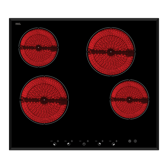
USER MANUAL PAGE 06 YOUR INALTO COOKTOP SPECIFICATIONS MODEL PRODUCT DIMENSIONS (W×D×H) CUT-OUT DIMENSIONS (W×D) IE60T 590mm, 520mm, 55mm 560mm x 490mm MODEL BURNERS OTHER x 1.80 kW radiant zones (Ø 190mm) Touch control operation 4 x Individual residual heat indicators 2 x 1.20 kW radiant zones (Ø... -
Page 7: Installation Instructions
PAGE 07 INSTALLATION INSTRUCTIONS It’s important to carefully read the following installation instructions before beginning the installation of your cooktop. IMPORTANT! The connection of this cooktop must be carried out by a suitably qualified and licensed person, in accordance with the current version of the following: ►... - Page 8 USER MANUAL PAGE 08 INSTALLATION INSTRUCTIONS LOCATING THE FI ING BRACKETS The unit should be placed on a stable, smooth surface (use the packaging). Do not apply force onto the controls protruding from the hob. Fix the hob on the work surface by screw four brackets on the bottom of hob (see picture) after installation. Adjust the bracket position to suit for different work surface’s thickness.
- Page 9 PAGE 09 CONNECTING THE HOB TO THE MAINS POWER SUPPLY The power supply should be connected in compliance with the relevant standard, or a single-pole circuit ► breaker. The method of connection is shown below. If the cable is damaged or needs replacing, this should be done by an after-sales technician using ►...
-
Page 10: Operating Your Cooktop
USER MANUAL PAGE 10 OPERATING YOUR COOKTOP BEFORE FIRST USE IMPORTANT! You should clean the ceramic cooktop surface (refer to the “Cleaning and Maintenance” section). ► You should switch on one cooking zone at a time, for 5 minutes at the maximum setting. This will help to eliminate any new smell that exists and evaporate any humidity that has formed on the heating elements during transit. -
Page 11: Choosing The Right Cookware
PAGE 1 1 OPERATING YOUR COOKTOP CHOOSING THE RIGHT COOKWARE Do not use cookware with jagged edges or a curved base. Make sure that the base of your pan is smooth, sits flat against the glass, and is the same size as the cooking zone. -
Page 12: To Start Cooking
USER MANUAL PAGE 12 TO START COOKING Do not use cookware with jagged edges or a curved base. After power on, the buzzer beeps once, all the indicators light up for 1 second ► then go out, indicating that the ceramic hob has entered the state of standby mode. - Page 13 PAGE 13 RESIDUAL HEAT INDICATORS ► After a zone is switched off, the corresponding cooking zone will show an “H” in the control panel. This means that the temperature of the zone still high enough to cause injury. ► The residual heat indicator will go out when the surface has cooled down to a safe temperature. ►...
-
Page 14: Using The Timer As A Minute Minder
USER MANUAL PAGE 14 OPERATING YOUR COOKTOP USING THE TIMER You can use the timer in two different ways: ► You can use it as a minute minder. In this case, the timer will not turn any cooking zone off when the set time is up. ►... - Page 15 PAGE 15 SETTING THE TIMER TO TURN ONE OR MORE COOKING ZONES OFF If the timer is set on one zone: Touch the”-“ or ”+” of the corresponding cooking ► zone that want to set the timer for. Set the time by touching the “-“ or “+” control of the timer. ►...
- Page 16 USER MANUAL PAGE 16 If the timer is set on more than one zone: When you set the time for several cooking zones simultaneously, decimal dots ► of the relevant cooking zones are on. The minute display shows the min. timer. The dot of the corresponding zone flashes.
-
Page 17: Cooktop Guidelines
PAGE 17 OPERATING YOUR COOKTOP COOKTOP GUIDELINES ► The first few times the cooktop is used, it may give off a burning smell. This smell will disappear completely with repeated use. ► The cooktop surface is fitted with cooking areas of different diametre and power. ►... -
Page 18: Cleaning And Maintenance
USER MANUAL PAGE 18 CLEANING & MAINTENANCE By ensuring proper cleaning and maintenance of your Inalto cooktop, you can ensure that it will have a long and fault free operation. WARNING! Do not start cleaning the cooktop until it has completely cooled. -
Page 19: Troubleshooting
PAGE 19 TROUBLESHOOTING OPERATION IN CASE OF EMERGENCY IMPORTANT! If your appliance appears to be operating incorrectly, then you should disconnect it from your mains gas and electrical supply and then contact the Residentia Group Support team on 1300 11 HELP (4357). -
Page 20: Technical Data
USER MANUAL PAGE 20 TECHNICAL DATA ELECTRICAL DETAILS Rated Voltage: 220 - 240 Volts, 50-60 Hz Supply Connection: 30A (double pole switch fuse outlet with 3mm contact gap) Max Rated Inputs: 6.0kW Mains Supply Lead: 3 core x 4mm² (not supplied) -
Page 21: Warranty Information
PAGE 21 WARRANTY INFORMATION WARRANTY TERMS & CONDITIONS IN THIS WARRANTY COOKING APPLIANCES ‘acceptable quality’ as referred to in clause 10 of this (BUILT-IN OVENS, COOKTOPS) warranty has the same meaning referred to in the ACL; ‘ACL’ means Trade Practices Amendment (Australian This document sets out the terms and conditions of the Consumer Law) Act (No.2) 2010;... - Page 22 USER MANUAL PAGE 22 Proof of purchase is required before you can make a At all times during the Warranty Period, Residentia claim under this warranty. Group shall, at its discretion, determine whether You may not make a claim under this warranty unless repair, replacement or refund will apply if an the defect claimed is due to faulty or defective parts Appliance has a valid warranty claim applicable to it.
-
Page 23: Purchase Details
PAGE 23 PURCHASE DETAILS For your records, please record details of your purchase below and staple your receipt on the opposite page. STORE DETAILS STORE NAME ADDRESS TELEPHONE PURCHASE DATE PRODUCT DETAILS MODEL NO. SERIAL NO.* * Note. Your serial number can be found on the underside of the cooktop. - Page 24 USER MANUAL PAGE 24 RECEIPT...
-
Page 25: Model Code / S
MODEL CODE / S IE60T...
Need help?
Do you have a question about the IE60T and is the answer not in the manual?
Questions and answers