Sign In
Upload
Manuals
Brands
Woodward Manuals
Controller
L-Series
Woodward L-Series Manuals
Manuals and User Guides for Woodward L-Series. We have
3
Woodward L-Series manuals available for free PDF download: Installation And Operation Manual
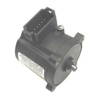
Woodward L-Series Installation And Operation Manual (130 pages)
Integrated Speed Control
Brand:
Woodward
| Category:
Controller
| Size: 1.5 MB
Table of Contents
Table of Contents
3
Regulatory Compliance
7
Electrostatic Discharge Awareness
8
Chapter 1. General Information
9
Purpose and Scope
9
How to Use this Manual
9
Intended Applications
9
Introduction
10
Basic Control Options
11
Programmable Features
11
Service Tool Software
12
Chapter 2. Mechanical Installation
13
Introduction
13
General Installation, Operation Notes and Requirements
13
Unpacking
14
Mechanical Installation
14
Figure 2-1. Linkage Design Examples
16
Figure 2-2. L-Series Outline Drawing
18
Figure 2-3. L-Series Cover Types
19
Figure 2-4A. L-Series Shaft Types
20
Figure 2-4B. L-Series Shaft Types
21
Figure 2-4C. L-Series Shaft Types
22
Chapter 3. Electrical Installation
23
Introduction
23
Shielded Wiring
23
Figure 3-1A. Typical L-Series Speed Control Application Wiring
25
Description of Electrical I/O
26
Figure 3-1B. L-Series Speed Control Connector Pin Arrangement
26
Figure 3-2. Correct and Incorrect Wiring to Power Supply
27
Figure 3-3. MPU Speed Sensing Input
28
Figure 3-4. Proximity Probe Speed Sensing Input
29
Figure 3-5. Ignition Speed Sensing Input
29
Figure 3-6. TPS Output
30
Figure 3-7. Relay Driver Output
31
Figure 3-8. Typical AUX Input Usage
33
Figure 3-9. Ground Junction Point
35
Chapter 4. Description of Operation
36
General
36
System Operation
37
Starting the Engine
37
Control Features Description
37
Speed Control Functions
38
Figure 4-1 Overview of L-Series Inputs/Outputs
38
Figure 4-2 Speed Setpoint Actions and Rates
39
Figure 4-3. 5% Droop Example
43
Figure 4-4 Remote Speed Setpoint
44
Speed Control Dynamics
45
Figure 4-5. Dual Gain Settings
46
Start Fuel Limiting
47
Figure 4-6. Single Start Fuel Limit
47
Runtime Fuel Limiting
48
Figure 4-7. Dual Start Fuel Limiters
48
Figure 4-8. Boost (External) Fuel Limit Curve
49
Temperature Sensing
50
Current Limiting Based on Temperature
50
Figure 4-9. Runtime Fuel Limit Curve
50
Control Modes
51
Fault Detection and Annunciation
52
Faults
52
Chapter 5. Service Tool
56
Introduction
56
Description
56
Figure 5-1. Example Service Tool Screen
56
Figure 5-2A. Programming Harness Connections
57
Getting Started
58
Figure 5-2B. Programming Harness Wiring
58
Monitoring the Driver
59
Figure 5-3A. Service Tool-Overview Tab
61
Figure 5-3B. Service Tool-Overview Tab (5418-2193 Software Only)
61
Figure 5-4. Service Tool-Alarms Tab
63
Figure 5-5. Service Tool-Shutdowns Tab
64
Figure 5-6. Service Tool-Internal Shutdowns Tab
64
Figure 5-7. Service Tool-Simulated I/O Tab
65
Figure 5-8. Service Tool-Identification Tab
66
Chapter 6. Configuration
67
Overview
67
Configuration Parameters
68
Figure 6-1. Configuration Selection Options
68
Figure 6-2. Configuration Editor-OVERVIEW TAB
69
Figure 6-3. Configuration Editor-SETPOINT TAB
71
Figure 6-4. Configuration Editor-CONTROL TAB
73
Figure 6-5. Configuration Editor-Modifiers Tab
77
Figure 6-6A. Configuration Editor-Fuel Limiting Tab (5418-1680 and -2226 Software Versions)
79
Figure 6-6B. Configuration Editor-Fuel Limiting Tab (5418-2193 Software Only)
80
Figure 6-6C. Configuration Editor-Fuel Limiting Tab (5418-2193 Software Only)
80
Figure 6-7. Configuration Editor-Dynamics Tab
83
Figure 6-8. Configuration Editor-Discrete I/O Tab
85
Figure 6-9. Configuration Editor-Alarm/Shutdown Tab
88
Figure 6-10. Configuration Editor-Security Tab
90
Figure 6-11. Security Tab Set Password Pop-Up
91
Figure 6-12. Password Entry Prompt
91
Load Configuration File to Control
92
Figure 6-13. Configuration Loading
92
Figure 6-14. Direct Load of Configuration File
92
Configuration Checks
93
Chapter 7. Setup and Tuning
96
Introduction
96
Tuning the Speed PID
96
Editing of Configuration Settings
97
Figure 7-1. Service Tool-Speed Dynamics
97
Figure 7-2A. Edit Configuration Settings Menu (5418-2193 Software Only)
98
Figure 7-2B. Speed Input Window (5418-1680 and -2226 Software Versions)
98
Tuning the Position PID
99
Figure 7-2C. Configuration Settings Window (5418-2193 Software Only)
99
Figure 7-3. Service Tool-PID Tuning Window
100
Figure 7-4. Service Tool-PID Tuning Properties Window
100
Position Calibration and Verification
101
Calibration Sequence Overview
101
Figure 7-5. Service Tool-Manual Position Calibration Selection
101
Position Verification
102
Figure 7-6. Service Tool-Verify Position Calibration
102
Figure 7-7. Service Tool-Manual Position Calibration
103
Figure 7-8. Service Tool-Manual Position Calibration Settings
104
Figure 7-9. Service Tool-Auto Position Calibration
105
Chapter 8. Troubleshooting
106
Introduction
106
General System Troubleshooting Guide
107
Engine/Generator Troubleshooting
107
Troubleshooting Diagnostic Fault Flags
111
Electrical Troubleshooting Guide
115
Chapter 9. Service Options
117
Product Service Options
117
Returning Equipment for Repair
118
Replacement Parts
119
How to Contact Woodward
119
Engineering Services
120
Technical Assistance
121
Appendix A. Acronyms/Abbreviations
122
Appendix B. L-Series Control Specifications
123
Figure B-1. Bode Plot of L-Series Response
127
Declarations
128
Advertisement
Woodward L-Series Installation And Operation Manual (70 pages)
Position Controller
Brand:
Woodward
| Category:
Controller
| Size: 0.81 MB
Table of Contents
Table of Contents
3
Regulatory Compliance
5
Electrostatic Discharge Awareness
6
Chapter 1. General Information
7
Purpose and Scope
7
How to Use this Manual
7
Intended Applications
7
Introduction
7
Programmable Features
8
Service Tool Software
9
Chapter 2. System Description/Application Overview
10
System Operation
10
Figure 2-1. PWM Linear Demand to Position
12
Figure 2-2. PWM Non-Linear Demand to Position
12
Figure 2-3. Analog 0-5 V Linear Demand to Position
13
Figure 2-4. Analog 0-5 V Non-Linear Demand to Position
13
Communications
14
Temperature Sensing
15
Current Limiting Based on Temperature
15
Faults
15
Chapter 3. Installation
19
Introduction
19
General Installation, Operation Notes and Requirements
19
Unpacking
20
Mechanical Installation
20
Figure 3-1. L-Series Outline Drawing
21
Figure 3-2. L-Series Cover Types
22
Figure 3-3A. L-Series Shaft Types
23
Figure 3-3B. L-Series Shaft Types
24
Electrical Installation
25
Figure 3-3C. L-Series Shaft Types
25
Description of Electrical I/O
27
Figure 3-4. Typical L-Series Position Control Application Wiring
27
Figure 3-5. Acceptable PWM Input Types
29
Figure 3-6. Relay Driver Output
30
Figure 3-7. Typical AUX1 and AUX2 Usage
31
Figure 3-8. Ground Junction Point
32
Chapter 4. Service Tool
33
Introduction
33
Description
33
Figure 4-1. Example Service Tool Screen
33
Figure 4-2A. Typical Programming Datalink Harness Wiring
34
Getting Started
35
Figure 4-2B. Programming Harness Wiring
35
L-Series Configuration
36
Configuration Parameters
37
Figure 4-3. Configuration Selection Options
37
Figure 4-4. Configuration Editor-Analog Settings
38
Figure 4-5. Configuration Editor-PWM Settings
40
Figure 4-6. Configuration Editor-Discrete Output Settings
41
Figure 4-7. Configuration Editor-Alarm/Shutdown Settings
42
Figure 4-8. Service Tool-Overview Tab
43
Figure 4-9. Service Tool-Alarms Tab
45
Figure 4-10. Service Tool-Shutdowns Tab
46
Figure 4-11. Service Tool-Internal Shutdowns Tab
46
Figure 4-12. Service Tool-Identification Tab
47
Position Calibration and Verification
48
Figure 4-13. Service Tool-PID Tuning Window
48
Figure 4-14. Service Tool-PID Tuning Properties Window
48
Calibration Sequence Overview
49
Position Verification
49
Figure 4-15. Service Tool-Verify Position Calibration
50
Figure 4-16. Service Tool-Manual Position Calibration
51
Figure 4-17. Service Tool-Manual Position Calibration Settings
51
Figure 4-18. Service Tool-Auto Position Calibration
52
Chapter 5. Troubleshooting
53
Introduction
53
General System Troubleshooting Guide
53
Engine/Generator Troubleshooting
54
Electrical Troubleshooting Guide
56
Chapter 6. Service Options
57
Product Service Options
57
Returning Equipment for Repair
58
Replacement Parts
59
How to Contact Woodward
59
Engineering Services
60
Technical Assistance
61
Appendix A. Acronyms/Abbreviations
62
Appendix B. L-Series Configuration Summary
63
Appendix C. L-Series Control Specifications
64
Figure C-1. Bode Plot of L-Series Response
67
Woodward L-Series Installation And Operation Manual (34 pages)
Brand:
Woodward
| Category:
Industrial Equipment
| Size: 1.59 MB
Table of Contents
Table of Contents
3
Warnings and Notices
5
Electrostatic Discharge Awareness
6
Regulatory Compliance
7
Chapter 1. General Information
9
Purpose and Scope
9
Intended Applications
9
L-Series Description
9
Determining Proper Valve Size
10
Figure 1-1. CV Vs Angle for L-Series Itbs
11
Figure 1-2. CV Vs Angle for L-Series Trim Valves
12
Chapter 2. Application Overview
13
Hardware Configuration Application Process
13
Figure 2-1. Application Matrix
13
Chapter 3. Installation
15
Mechanical Installation
16
Figure 3-1. Spring-Loaded Throttle Plate
17
Figure 3-2. L-Series ITB Outline Drawings
19
Figure 3-3A. LC-50 Outline Drawing (Small Bore)
20
Figure 3-3B. LC-50 Outline Drawing (Large Bore)
21
Applications (Mixer Applications)
22
Figure 3-4. Zirconia Oxygen Sensor Response
23
Figure 3-5. Pre-Catalyst Emissions
23
Figure 3-6. Post-Catalyst Emissions
23
Chapter 4. Troubleshooting
24
Chapter 5 Product Support and Service Options
25
Product Support Options
25
Product Service Options
25
Returning Equipment for Repair
26
Replacement Parts
26
Engineering Services
27
Contacting Woodward's Support Organization
27
Technical Assistance
28
L-Series Itb Specifications
29
Appendix . Acronyms /Abbreviations
30
Revision History
31
Declarations
32
Advertisement
Advertisement
Related Products
Woodward LS 4
Woodward LS-5 v2 Series
Woodward LS-522
Woodward LS-512
Woodward LS-5 Series
Woodward LS-521
Woodward easYgen LS-6XT
Woodward easYgen LS-612XT-P1
Woodward Large Electric Sonic Valve II
Woodward LESV II
Woodward Categories
Controller
Control Unit
Relays
Control Systems
Industrial Equipment
More Woodward Manuals
Login
Sign In
OR
Sign in with Facebook
Sign in with Google
Upload manual
Upload from disk
Upload from URL