BFT PHOBOS N BT Installer's Reference Manual
Hide thumbs
Also See for PHOBOS N BT:
- Installation and user manual (29 pages) ,
- Installation manual (24 pages) ,
- Installation manual (12 pages)
Table of Contents
Advertisement
Advertisement
Table of Contents

Related Manuals for BFT PHOBOS N BT


Summary of Contents for BFT PHOBOS N BT
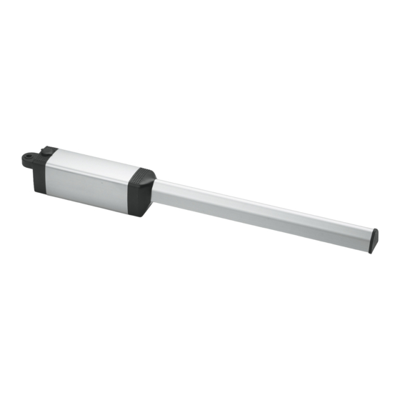
- Page 1 PHOBOS N BT & PHOBOS NL BT INSTALLER REFERENCE VERSION 101115...
- Page 2 APPLICATIONS AND CAPABILITIES Phobos N BT 32-1/2” OUTSIDE 90° 550 lbs 4” max hinge 10 feet offset* Phobos NL BT 37” OUTSIDE 110° 550 lbs 5” max hinge 16 feet offset* Maximum hinge offset does not apply to push to open applications...
-
Page 3: Installation Checklist
INSTALLATION CHECKLIST Determine the proper geometry. Pages 4 & 5. Install the Post bracket. Page 6 & 7. Install the Gate Bracket. Page 7. Install the magnet holder. Page 7 Wire the motors. Page 8. ... - Page 4 DEFINING THE BRACKET GEOMETRY A & B DIMENSIONS - For A and B dimensions, the measurement is taken from the center of the gate's hinge point to the center of the Phobos pivot point. Gate hinge Gate Gate frame post PHOBOS' PIVOT POINT PIVOT POINT For Push-to-Open applications, please call Tech Support at 877-995-8155...
- Page 5 If you are welding the post bracket, when possible, use the geometry in table 1: PHOBOS N BT 5-7/8”...
- Page 6 ARB BRACKET LENGTHS ARB BRACKET LENGTHS - To achieve the desired ARB length, use all 3 bolts on the holes that are represented by black dots on the illustration of the long bracket piece. Insert them only on the holes that are represented by black dots on the short bracket piece.
-
Page 7: Installing The Mounting Brackets
BOLT AND/OR WELD THE POST BRACKET ACCORDING TO YOUR GEOMETRY. BOLT AND/OR WELD THE GATE BRACKET ACCORDING TO YOUR GEOMETRY. Remember to measure the distance to C with a fully closed gate. Phobos N BT gate bracket Phobos N L BT gate bracket WELD OR BOLT 5-3/8”... -
Page 8: Installing The Actuator
INSTALLING THE ACTUATOR WIRE THE MOTORS - Before attaching the actuator to the mounting brackets, wire the motor cable and then install the protective cover as illustrated. WHITE 14 AWG STRANDED BLACK ATTACH THE ACTUATOR - Follow illustrations to install the actuator to the post and gate brackets. -
Page 9: Setting The Limit Switches
SETTING THE LIMIT SWITCHES 1) SET TO MANUAL OPERATION - Disengage the drive gear by using the triangular key and turning clockwise. 2) SET THE CLOSE LIMIT - Push the gate to its fully closed position. Remove the screw that holds the proximity sensor at the front end of the actuator. -
Page 10: Connecting The Motors
CONNECTING THE MOTORS DUAL MOTOR OPERATION 16 AWG SINGLE MOTOR OPERATION NOTE: For push to open applications, the RED and BLACK wires are reversed... -
Page 11: Control Inputs
CONTROL INPUTS PHOTOBEAM SENSOR WIRING RECEIVER TRANSMITTER Remove jumper ←18 Normally closed 14→ ←15 Common 13→ ←12 ←11 OPERATING DEVICES Opening devices such as exit probes, entry keypads and phone entry systems should be connected to terminals 15 (common) and 20 (open). Open and close devices such as single button push-buttons and external radio receivers should be connected to terminals 15 (common) and 16 (start) -
Page 12: Other Connections
OTHER CONNECTIONS STOP / RESET BUTTON Remove jumper Stop button or devices should be wired to terminals 15 (common) and 17 (stop). These must be normally closed contact devices. The factory installed jumper on terminal 17 must be removed. UL Block – When the system detects 2 consecutive physical obstructions, it stops the motors and ignores all additional commands. -
Page 13: Initial Programming
INITIAL PROGRAMMING NAVIGATE THE PROGRAMMING MENU Use the LCD display and the 3 buttons on the upper right corner of the Libra UL-R to navigate and manipulate the menu. Press the OK button twice to start. SELECT RADIO TRANSMITTER PROGRAMMING (ADD START) 1. - Page 14 INITIAL PROGRAMMING SETTING THE MOTOR SLOWDOWN MAIN MENU PARAM LOGIC M1 T Prior to setting the slowdown, you must time in seconds, RADIO M2 T LANGUAGE M1 T SLOW how long does it take for the gate to complete a stroke DEFAULT M2 T SLOW AUTOSET...
- Page 15 INITIAL PROGRAMMING MAIN MENU PARAM AUTOMATIC CLOSING TIMER (TCA) LOGIC RADIO 3 STEP Enabling the TCA. LANGUAGE IBL OPEN DEFAULT FAST CLS 1.From the MAIN MENU, select LOGIC. AUTOSET PHOTOC. OPEN TEST PHOT 2.From the LOGIC Sub-menu, select TCA. 1 MOT ON BLOC PERSIST 3.Switch ON by pressing the + button and then the OK button.
-
Page 16: Maintenance And Troubleshooting
Keep the screw-drive lubricated using BFT grease I101115. Do not apply grease if gears are dirty. If necessary, clean with solvent before applying. - Page 17 LIBRA BOARD TERMINALS 24 - ANTENNA GROUND (shielding) 23 - EXTERNAL ANTENNA 21 & 22 – UL BLOCK indicator. Normally open contacts that changes states (closes) during a UL Block condition. Intended for 3, 4 & 5 – MOTOR 2 (single connection of audible gate operation) connections.
- Page 18 PROGRAMMING MENU REFERENCE NAVIGATION BACK / EXIT DOWN SELECT MAIN MENU Press OK twice to enter to the programming MAIN MENU MAIN MENU DISPLAY DESCRIPTION PARAM (PARAMETERS SUB-MENU) Adjustment of all numerical values (torque, time, speed). LOGIC (LOGIC SUB-MENU) Enabling and disabling of features. RADIO (RADIO SUB-MENU) Adding and deleting of radio transmitters (remotes).
Need help?
Do you have a question about the PHOBOS N BT and is the answer not in the manual?
Questions and answers