
Related Manuals for Nice HySecurity CBOX936


Summary of Contents for Nice HySecurity CBOX936
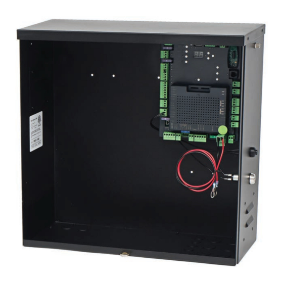
- Page 1 Installation and Programming Manual CBOX936 Vehicular gate operator control box with 936 control board CBOX with 936 control board www.ApolloGateOpeners.com | (800) 878-7829 | Sales@ApolloGateOpeners.com...
-
Page 2: Table Of Contents
CBOX936 INSTALLATION AND PROGRAMMING MANUAL CONTENTS LIST OF INSTRUCTIONS.....................2 SECTION 1: 936 CONTROL BOX OVERVIEW.............3 1.1 936 CONTROL BOARD FEATURES..................3 SECTION 2: 936 CONTROL BOX PARTS IDENTIFICATION.........5 SECTION 3: SAFETY AND UL325 USAGE CLASSES..........5 SECTION 4: 120VAC ELECTRICAL WIRING SAFETY..........11 4.1 HIGH VOLTAGE WIRE GAUGE REQUIREMENTS..............11 SECTION 5: INSTALLATION SAFETY.................12 SECTION 6: TOOLS &... -
Page 3: Section 1: 936 Control Box Overview
This manual provides documentation that covers the layout, CBOX936 is used in the following Nice installation, and programming of the Nice 936 control box for a gate operator systems with associated typical installation. Please consult your Nice distributor for more... - Page 4 CBOX936 INSTALLATION AND PROGRAMMING MANUAL CBOX936 SPECIFICATIONS OPEN/CLOSE TIME (TO 90°) 14 - 16 Seconds MAX. DEGREE OF OPENING Standard install = 105°, Special install = 120° SOLAR COMPATIBLE OPERATING TEMPERATURE -4º to 122º F (-20º to 50º C) DIMENSIONS 8.5”...
-
Page 5: Section 2: 936 Control Box Parts Identification
Some operators are restricted in their usage application. All Nice USA operators are approved for use in all four UL325 Usage Classes. Appropriate Usage Classes are shown in the Specifications. - Page 6 • The entrance is for vehicles only. Pedestrians must use • guarding is supplied for exposed rollers); separate entrance. • When utilizing a Nice 936 board, a maximum of 8 entrapment protection devices (6 BlueBUS and 2 pulse • Save these instructions.
- Page 7 CBOX936 INSTALLATION AND PROGRAMMING MANUAL PEDESTRIAN TRAFFIC CONTACT SENSORS (EDGE) The operator is intended for installation only on gates used For a gate operator utilizing a contact sensor (Edge): for vehicles. Pedestrians must be supplied with a separate • One or more contact sensors shall be located where access opening.
- Page 8 CBOX936 INSTALLATION AND PROGRAMMING MANUAL GENERAL GATE CONSTRUCTION REQUIREMENTS: automated. pGraDinG xistinG utomateD ates ypes Any existing automated gate, when the operator requires Gates shall be constructed in accordance with the replacement, shall be upgraded to conform to the provisions provisions given for the appropriate gate type listed.
- Page 9 INSTRUCTION 3 for swing gates, but there may be gate professional to correct the problem. other entrapment zones presented by the actual SAFETY DEVICE TESTING installation and adjacent structures or landscape that must be protected as well. All Nice gate operators www.ApolloGateOpeners.com | (800) 878-7829 | Sales@ApolloGateOpeners.com...
- Page 10 COMPATIBLE EXTERNAL SENSORS Only the following external sensors have been evaluated and tested with Nice 936 control boards and are approved to be used for protection against entrapment: • Nice BlueBUS Through-Beam Photo Eye •...
-
Page 11: Section 4: 120Vac Electrical Wiring Safety
BOX WITHOUT EARTH GROUND from appearing on the metal control box, the actuator, CONNECTION! or the gate itself. Nice recommends an 8 foot copper rod driven all the way into the ground with a copper clamp and 12ga copper wire minimum. GROUND... -
Page 12: Section 5: Installation Safety
* The gate being modified should be level and plumb and the gate should open easily and evenly. * Nice swing gate systems are NOT intended for installation on an incline. * These instructions assume actuator(s) has been installed per the applicable actuator installation manual. -
Page 13: Section 8: 936 Control Box Installation & Setup
CBOX936 INSTALLATION AND PROGRAMMING MANUAL SECTION 8: 936 CONTROL BOX INSTALLATION & SETUP MOUNT CONTROL BOX 1. Mount control box on same side as actuator (for dual gate systems, same side as MASTER actuator with shorter harness) and at least six feet away from the pivot arm (FIGURE 1-1). 2. -
Page 14: Instruction 2: Wire Actuator(S) To Control Board
CBOX936 INSTALLATION AND PROGRAMMING MANUAL WIRE ACTUATOR(S) TO CONTROL BOARD NOTE: Refer to 912L actuator (MX4685) or 816-X actuator (MX4684) manuals for specific instructions and diagrams for wiring the actuator to the 936 control board. 1. Strip actuator wires back 1/4”-5/16” (7- 8mm) and twist. -
Page 15: Instruction 3: Determining Bluebus Photo Eye Locations
CBOX936 INSTALLATION AND PROGRAMMING MANUAL DETERMINING BLUEBUS PHOTO EYE LOCATIONS See below for suggestions of photo eye positioning for your gate configuration. NOTE: Name designations in IMAGE 3-1 (P1, P2, etc.) are arbitrary designations used to indicate jumper settings for each photo eye location. See INSTRUCTION 4 for jumper settings. IMAGE 3-1: POSSIBLE ENTRAPMENT ZONES AND PHOTO EYE LOCATIONS P2 (Close Direction) P3 and P4 (Close Direction) -
Page 16: Instruction 4: Prepare Bluebus Photo Eyes For Install
CBOX936 INSTALLATION AND PROGRAMMING MANUAL IMPORTANT! The 936 control board will not operate without at least one monitored and functioning safety device connected to the control board. Before power is connected to the control board, install either the BlueBUS through-beam photo eyes per the instructions below or an alternative photo eye, such as the reflective EMX NIR-50-325 photo eye (per the instructions provided separately) before attempting to apply power to the control board. -
Page 17: Instruction 5: Install & Wire Bluebus Photo Eyes
CBOX936 INSTALLATION AND PROGRAMMING MANUAL INSTALL & WIRE BLUEBUS PHOTO EYES 1. Ensure alignment between receiver and transmitter brackets (H), then affix both to selected locations with included screws (I). IMPORTANT! If using the model EPMB/A non-adjustable photo eye (H), ensure the mounting surfaces for both devices are parallel with each other to ensure accurate alignment between TX and RX. -
Page 18: Instruction 6: Connect Bluebus Photo Eyes To Board
CBOX936 INSTALLATION AND PROGRAMMING MANUAL CONNECT BLUEBUS PHOTO EYES TO BOARD If the kit comes with BlueBUS photo eye pair, connect bus wires (no polarity) into 2-pin BlueBUS connector on control board (IMAGE 6-1). If an alternative reflective photo eye and reflector are provided, follow installation instructions included in the kit. -
Page 19: Power Options And Wiring
CBOX936 INSTALLATION AND PROGRAMMING MANUAL POWER OPTIONS AND WIRING There are two possible configurations available to power the 936 control board: • 12 VDC battery charged by solar panel • 12 VDC battery charged by AC-DC charger applied to battery DANGER! DO NOT CONNECT AC POWER DIRECTLY TO MAIN DC POWER CONNECTOR ON CONTROL BOARD! -
Page 20: Instruction 9A: Solar Panel Connection - 10W To 20W
• If solar panel is wired backwards, a red LED will illuminate above the connector. NOTE: For 30W solar panels and above, an external regulator must be used. Nice offers a regulator (P/N SG-4) for this purpose. See INSTRUCTION 9B for installation instructions for the SG-4 regulator. -
Page 21: Instruction 9B: Solar Panel Connection - 30W And Above
Solar panels of 30W and above must be connected to a regulator which, in turn, then connects to the battery to enable battery charging. Nice offers a regulator (P/N SG-4) for this purpose. For regulators sourced elsewhere, follow the manufacturers instructions when installing. Install and wire the 30W and above solar panels and SG-4 regulator as follows: 1. -
Page 22: Instruction 10: Power Up Control Board
6. Once safety devices (such as photo eyes) are found and determined to be functional, proceed to INSTRUCTION 11. 7. If safety devices provided in the kit are determined to be defective, contact Nice technical support. GATE LIMIT LEARNING PROCEDURE Before performing the fine adjustment to gate limits, the 936 control board must first “learn”... -
Page 23: Gate Limit Learning Procedure
CBOX936 INSTALLATION AND PROGRAMMING MANUAL GATE LIMIT LEARNING PROCEDURE 1. The control board should already be powered from battery connection. If not, apply power per INSTRUCTION 8. MOTOR 1 “CLOSE MOTOR 2 “CLOSE LIMIT” LED (RED) LIMIT” LED (RED) MOTOR 1 “OPEN MOTOR 2 “OPEN LIMIT”... -
Page 24: Instruction 12: Select Control Board Standby Mode
CBOX936 INSTALLATION AND PROGRAMMING MANUAL 11: GATE LIMIT LEARNING PROCEDURE (CONT.) 7. If a dual gate system, plug both actuator motor connectors into Control Board, ensuring that the second actuator with longer cable is plugged into MOTOR 2 connector. Press the OK button. The board automatically begins the limit learning process and the gate(s) moves automatically as follows: a) A short opening sequence at half speed to determine the number of motors. -
Page 25: Instruction 13: Bluebus Photo Eye Status & Troubleshooting
CBOX936 INSTALLATION AND PROGRAMMING MANUAL BLUEBUS PHOTO EYE STATUS & TROUBLESHOOTING Once photo eyes are recognized by the control board, the photo eye LED behavior should be checked and adjustments made as follows: 1. After power up and all BlueBUS devices are recognized, observe LED behavior in each photo eye. 2. -
Page 26: Instruction 14: Bluebus Photo Eye Alignment
CBOX936 INSTALLATION AND PROGRAMMING MANUAL BLUEBUS PHOTO EYE ALIGNMENT If adjustment of photo eye alignment is necessary, refer to the following instructions: NOTES: Photo eye testing is described in INSTRUCTION 15. Adjustment instructions apply only to EPMOB/A and EPLOB/A models. EPMB/A model is not adjustable, and must be adjusted using other mechanical means left up to the installer. -
Page 27: Instruction 15: Bluebus Photo Eye Testing
CBOX936 INSTALLATION AND PROGRAMMING MANUAL BLUEBUS PHOTO EYE TESTING Photo eyes must be tested after power is applied to the control board to ensure proper operation: 1. Apply power to control board and ensure BlueBUS devices are detected and functioning. 2. -
Page 28: Instruction 17: Installing The Audio Alarm
CBOX936 INSTALLATION AND PROGRAMMING MANUAL INSTALLING THE AUDIO ALARM IMPORTANT! The installer MUST connect the included audio alarm per these instructions. Installing the audio alarm is REQUIRED for UL325 compliance. The audio alarm (siren) included in the kit must be connected to the 936 control board to provide an audible alarm to indicate a hard shutdown of the system, which is triggered by two consecutive entrapment events. -
Page 29: Instruction 18: Assigning New Remote Control
LED lights up on the side of the receiver, then release the button. 2. Within 10 seconds, press and hold any key on the Nice remote control until the LED in the Nice receiver blinks green 3 times, indicating that the remote control is programmed to control the receiver. -
Page 30: Instruction 19: Deleting Single Remote Control
1. Press and hold the button on the side of the Nice receiver (on 936 board) until the LED on the Nice receiver illuminates green and keep the button pressed. The LED will illuminate after approximately 4 seconds. -
Page 31: Section 9: 936 Board Programming & Controls
CBOX936 INSTALLATION AND PROGRAMMING MANUAL SECTION 9: 936 BOARD PROGRAMMING & CONTROLS This section describes the navigation, menu, and programming controls for the 936 control board. See FIGURE 9-1 (below) and TABLE 21-1 (next page) for identification of the controls used to navigate and select various options, and the following pages for descriptions and diagrams of menus and the options available for programming. -
Page 32: Instruction 21: Control Board Menu Navigation
CBOX936 INSTALLATION AND PROGRAMMING MANUAL CONTROL BOARD MENU NAVIGATION Refer to FIGURE 21-1 on previous page for image of 936 control board layout, LED indicators, and controls. Menus and parameters are accessed and selected by pressing the buttons on the 936 control board as shown in Table 21-1: TABLE 21-1: 936 CONTROL BOARD BUTTON FUNCTIONS BUTTON... -
Page 33: Programming The 936 Control Board
CBOX936 INSTALLATION AND PROGRAMMING MANUAL PROGRAMMING THE 936 CONTROL BOARD 936 CONTROL BOARD PROGRAMMING OPTIONS Fc = Amount of force needed to cause the gate to stop and retract when hitting an FORCE BUTTON obstacle. SLOWDOWN BUTTON SP = Amount of slowdown (%) of gate as it nears open and close limits AUTO-CLOSE BUTTON AC = Number of seconds after opening that gate automatically closes. - Page 34 CBOX936 INSTALLATION AND PROGRAMMING MANUAL AUTO CLOSE BUTTON This option adjusts amount of time before gate automatically closes. Press the AUTO CLOSE Button. “AC” momentarily appears in the display, followed by the default of either “0” or the value last selected. Use the UP and DOWN buttons to choose 1 to 90 seconds, then press OK to accept selection.
- Page 35 CBOX936 INSTALLATION AND PROGRAMMING MANUAL RUN ALARM If an audio alarm is connected, Run Alarm determines how the audible alarm (or strobe) behaves when it is triggered. Values are as follows: • 0 = OFF (default) • 1 = Alarm sounds for 4 seconds before gate travel. •...
- Page 36 CBOX936 INSTALLATION AND PROGRAMMING MANUAL SOLENOID LOCK Solenoid Lock allows a solenoid lock to be engaged after the gate closes, but also introduces a slight delay (1 second) in gate open and closing to allow solenoid lock to engage and disengage. Values are as follows: •...
-
Page 37: Lcd Status And Error Displays
CBOX936 INSTALLATION AND PROGRAMMING MANUAL LCD STATUS AND ERROR DISPLAYS TABLE 9-1: LCD STATUS AND ERROR DISPLAY DESCRIPTIONS FLASHING Board in unlearned state. Learn button has been pressed and board ready for learn cycle. Pressing OK SOLID button begins the learn cycle. “Chasing Cursor”... -
Page 38: Section 10: Accessory Connections
CBOX936 INSTALLATION AND PROGRAMMING MANUAL SECTION 10: ACCESSORY CONNECTIONS This section describes the accessory functions, connections, and wiring for the 936 control board. See FIGURE 10-1 (below) for a visual representation of all the accessory inputs and outputs, and the following pages for a description of the I/O connectors and functions. -
Page 39: 10.1 Accessory Power Outputs
CBOX936 INSTALLATION AND PROGRAMMING MANUAL COMMUNICATIONS BlueBUS ACCESSORY INPUT INPUTS ACCESSORY OUTPUTS MOTOR POWER OUTPUTS INPUTS FIGURE 10-2: GENERAL I/O - 936 CONTROL BOARD 10.1 ACCESSORY POWER OUTPUTS Refer to FIGURE 10-1 for locations (red callouts) of the five accessory power outputs, which are described below. 24VDC 0.3A POWER OUTPUT This terminal is an internally fused (0.3A) output for powering external 24V DC accessories. -
Page 40: 10.2 Accessory Inputs
CBOX936 INSTALLATION AND PROGRAMMING MANUAL 10.2 ACCESSORY INPUTS Refer to FIGURE 10-1 and 10-2 for locations of the accessory inputs, which are described below. AUXILIARY INPUT “A”; PROGRAM OPTION “P2” This connector may be programmed (in OPTIONS) to accept 300 Hz pulse safety devices (safety or entrapment) or by default used as a step-by-step input. -
Page 41: 10.3 Accessory Outputs
CBOX936 INSTALLATION AND PROGRAMMING MANUAL FIRE INPUT Normally Open (NO) dry contact input for use as a Fire Department control switch that opens and holds gate open until the fire input is removed. BLUEBUS INPUT 2-wire non-polarized connection to BlueBUS enabled accessories. Provides monitored sensor input. AUXILIARY INPUT “C”;... -
Page 42: 10.4 Emergency Vehicle Access
CBOX936 INSTALLATION AND PROGRAMMING MANUAL 10.4 EMERGENCY VEHICLE ACCESS The automatic vehicular gate system must be designed to allow access to emergency vehicles under different operating conditions. Read all the following information. Make sure that your gate operating system is compliant with all local codes and regulations and that access for emergency vehicles is assured. -
Page 43: 10.5 Communication Bus
OVIEW CONTROLLER: • The Oview controller is an optional programming and diagnostic tool, which plugs directly into the 936 control board using an RJ45 network cable and is part of the Nice “Opera” control system. • The Oview controller can be used in “stand-alone” mode via its front-panel keypad. -
Page 44: Section 11: Appendix
CBOX936 INSTALLATION AND PROGRAMMING MANUAL SECTION 11: APPENDIX 11.1 CALCULATE SOLAR REQUIREMENTS CALCULATE SOLAR REQUIREMENTS 1. Estimate the gate traffic measured in open/close cycles per TABLE 22-1. TABLE 22-1: SOLAR PANEL WATT/CYCLE CHART DAILY CYCLES 1-10 1-20 1-40 1-60 1-80 80+ 5 Watt Solar Panel 10 Watt Solar Panel 20 Watt Solar Panel... -
Page 45: Maintenance Schedule
CBOX936 INSTALLATION AND PROGRAMMING MANUAL 11.2 MAINTENANCE SCHEDULE MAINTENANCE SCHEDULE Component Maintenance Action Annually Months Activate the primary (inherent) reverse system by blocking the gate with a solid object. The gate should reverse momentarily then stop. Re- ALARM start the gate and block again with a solid ob- ject. -
Page 46: System Troubleshooting
CBOX936 INSTALLATION AND PROGRAMMING MANUAL 11.3 SYSTEM TROUBLESHOOTING SYSTEM TROUBLESHOOTING Problem Possible Solution • Check the UL/Edge input on the gate controller. Gate opens a short • Ensure limit LEDs are functioning properly. distance, then stops and • Check for obstructions. reverses. -
Page 47: Installation Checklist
CBOX936 INSTALLATION AND PROGRAMMING MANUAL 11.4 INSTALLATION CHECKLIST • The installer and customer must each ensure that all of the following actions have been completed. • Left box is for installer check off and the right box is for customer check off. INSTALLATION CHECKLIST The gate has been checked to make sure it is level and moves freely in both directions. -
Page 48: Section 12: Part Drawings
CBOX936 INSTALLATION AND PROGRAMMING MANUAL SECTION 12: PART DRAWINGS www.ApolloGateOpeners.com | (800) 878-7829 | Sales@ApolloGateOpeners.com... - Page 49 CBOX936 INSTALLATION AND PROGRAMMING MANUAL www.ApolloGateOpeners.com | (800) 878-7829 | Sales@ApolloGateOpeners.com...
- Page 50 CBOX936 INSTALLATION AND PROGRAMMING MANUAL www.ApolloGateOpeners.com | (800) 878-7829 | Sales@ApolloGateOpeners.com...
-
Page 51: Section 13: Warranty
This warranty will be interpreted, construed, and enforced in all respects in the name plate of a manufacturer other than HySecurity or Nice and they are not a accordance with the laws of the State of Washington, without reference to its part of the base model. - Page 52 CBOX936 INSTALLATION AND PROGRAMMING MANUAL DOCUMENT REVISIONS NAME DESCRIPTION OF CHANGE DATE Curtis Harvey Rev A: Release for publication. 11/13/2019 INSTALLATION INFORMATION AND SIGN-OFFS Installation Acceptance Address where opener is located Installer name, number and address End user name and telephone number www.ApolloGateOpeners.com | (800) 878-7829 | Sales@ApolloGateOpeners.com...
Need help?
Do you have a question about the HySecurity CBOX936 and is the answer not in the manual?
Questions and answers