Table of Contents
Advertisement
Quick Links
User Manual
GE Digital Solutions
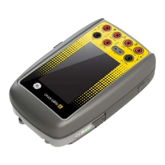
Druck DPI620 Genii
Intrinsically Safe Calibrator
and Communicator Series
User Manual – 116M5464
© 2016 General Electric Company. All Rights Reserved. Specifications are
subject to change without notice. GE is a registered trademark of General
Electric Company. Other company or product names mentioned in this
document may be trademarks or registered trademarks of their respective
companies, which are not affiliated with GE
Druck DPI 620G-IS
Advertisement
Table of Contents
Troubleshooting

Related Manuals for Druck DPI620 Genii


Summary of Contents for Druck DPI620 Genii
- Page 1 User Manual Druck DPI 620G-IS GE Digital Solutions Druck DPI620 Genii Intrinsically Safe Calibrator and Communicator Series User Manual – 116M5464 ...
-
Page 2: Table Of Contents
User Manual Druck DPI620G-IS Contents 1 Overview ......................... 10 1.1 Equipment in the Box .................. 10 1.2 Optional Items .................... 11 1.3 Observance of the User Manual .............. 11 1.4 Safety ...................... 12 General Safety Precautions .............. 12 Operation in a Hazardous Environment .......... 13 General Warnings ................... 15 Electrical warnings .................. 16 Pressure Warnings .................. 18 1.5 Preparing the Instrument ................ 19 1.6 Battery & Charger ................... 20 Charging the Battery ................ 20 Installing the Battery ................ 22 ... - Page 3 User Manual Druck DPI620G-IS Alarm Status .................... 27 Operating Modes .................. 28 1.9 Software and Firmware Upgrades .............. 29 Viewing Software Revision .............. 29 Upgrading the Unit Software .............. 29 Upgrading the HART Device Library ............ 31 1.10 Maintenance .................... 33 Cleaning .................... 33 1.11 Instrument Return .................. 34 Returned Material Procedure for USA ............ 34 Returned Goods Procedure for Europe .......... 35 Instrument Disposal in the European Union ........... 36 ...
- Page 4 User Manual Druck DPI620G-IS 2.5 Measure and Source Operations .............. 52 2.6 Example Procedure: Measure or Source Current ........... 54 Example Procedure: Measure or Source Current, CH1...... 54 Example Procedure: Measure or Source Current, CH2...... 55 2.7 Example Procedure: Measure or Source Current with Internal 15V Loop Power, CH2 ......................... 56 Example Procedure: Measure Current, Internal Loop Power, CH2 .. 57 Example Procedure: Source Current with Internal Loop Power, CH2 .. 58 2.8 Example Procedure: Measure DC Voltage ............ 59 Example Procedure: Measure DC Voltage, CH1 ........ 59 Example Procedure: Measure DC Voltage, CH2 ........ 60 2.9 Example Procedure: Source DC Voltage, CH1 .......... 61 2.10 Example Procedures: Measure or Source Frequency Signals ...... 62 Example Procedure: Measure Frequency Signals ........ 62 Example Procedure: Source Frequency Signals ........ 63 2.11 Example Procedure: Measure/Simulate RTD .......... 64 ...
- Page 5 User Manual Druck DPI620G-IS 3.3 Procedure Overview .................. 80 3.4 Set up a Leak Test ................... 83 3.5 Set the Pressure Module to Zero .............. 85 3.6 Error Indications .................... 86 4 Data Logging Operation .................. 87 4.1 Set‐up ...................... 89 4.2 Operation ...................... 91 4.3 File Review ...................... 91 4.4 Chart View ....................... 92 4.5 File Management .................... 93 Erase ...................... 93 Memory Status .................. 93 Download Files .................. 94 ...
- Page 6 User Manual Druck DPI620G-IS 6.5 External Loop Power .................. 108 6.6 Communicator Attached to a Network ............ 109 6.7 Use of Test Connections ................ 110 6.8 Viewing Primary Variables ................ 111 Device Polling .................. 112 Viewing HART® Configuration ............... 114 6.9 Start HART® SDC Application ................ 115 6.10 HART® Toolbar .................... 117 6.11 Data Display .................... 118 6.12 Editing Values .................... 119 6.13 Executing Methods .................. 121 Method Example ‐ Self‐test .............. 122 Method Example ‐ Analog Trim ............ 123 6.14 Preferences .................... 125 ...
- Page 7 User Manual Druck DPI620G-IS 8.1 Introduction .................... 135 8.2 FOUNDATION Fieldbus Configurations ............ 135 8.3 Start up ...................... 136 FOUNDATION™ Fieldbus Connections .......... 138 8.4 FOUNDATION™ Fieldbus Application – Connecting to a Network .... 142 FOUNDATION™ Fieldbus Toolbar ............ 143 Scanning For Devices ................ 145 Context Sensitive Menu ................ 148 Device State .................. 150 Troubleshooting Connection Problems .......... 154 8.5 FOUNDATION™ Fieldbus Application – Communication ...... 155 Device Focus View ................. 155 Block Navigation Tree ................ 158 Block Header Bar ................... 160 ...
- Page 8 User Manual Druck DPI620G-IS 9 PROFIBUS PA Fieldbus .................. 177 9.1 Introduction .................... 177 9.2 PROFIBUS Configurations ................ 177 9.3 Start‐up ...................... 178 PROFIBUS Connections ................. 180 9.4 PROFIBUS Application – Connecting to a Network ........ 184 PROFIBUS Toolbar ................. 185 Scanning For Devices ................ 187 Context Sensitive Menu ................ 190 Troubleshooting Connection Problems .......... 192 9.5 PROFIBUS Application – Communication ............. 193 Device Focus View ................. 193 Block Navigation Tree ................ 196 Block Header Bar ................... 198 ...
- Page 9 User Manual Druck DPI620G-IS 10.1 Before Starting .................... 214 10.2 Selection Sequence .................. 217 10.3 Calibration Procedures (CH1/CH2): Current (measure) ........ 218 10.4 Calibration Procedures (CH1/CH2): Current (source) ........ 220 10.5 Calibration Procedures (CH1/CH2): DC mV/Volts (measure) ....... 221 10.6 Calibration Procedures (CH1): DC mV/Volts (source) ........ 223 10.7 Calibration Procedures (CH1): Frequency (measure/source) ....... 225 10.8 Calibration Procedure (CH1): Frequency, Pulse Amplitude (source) .... 229 10.9 Calibration Procedure (CH1): Resistance (measure) (standard) .... 231 10.10 Calibration Procedure (CH1): Resistance (measure) (True Ohms) ... 233 10.11 Calibration Procedures (CH1): Resistance (source) ........ 234 10.12 Calibration Procedures (CH1): TC mV (measure) ........ 236 ...
-
Page 10: Overview
User Manual Druck DPI620G-IS Overview The Druck DPI 620 Genii Intrinsically Safe (DPI620G-IS) is a battery-powered instrument for use in a hazardous area. It is capable of electrical measure and source operations, HART®, Foundation Fieldbus and Profibus digital communications. It also supplies the power and user interface functions for all optional items. -
Page 11: Optional Items
User Manual Druck DPI620G-IS Optional Items The items that follow are optional items which can be used with the DPI620G-IS: • Pressure Module Carrier, MC 620-IS: this attaches directly to the DPI620G-IS to make a fully integrated pressure instrument. • Pressure Module, PM 620-IS: this attaches to the... -
Page 12: Safety
User Manual Druck DPI620G-IS Safety General Safety Precautions Read and obey all the operator's local Health and Safety regulations and Safe Working Procedures or Practices. When performing a procedure or task: • Use only the approved tools, consumable materials and spares to operate and maintain the equipment. -
Page 13: Operation In A Hazardous Environment
Ex ib IIC T4 Gb (-10°C ≤ Ta ≤ +50°C). For full details, refer to the ‘Intrinsic Safety and Quick Start’ guide. Use only Druck battery pack part number IO620G-IS- BATTERY. Special Conditions for Safe Use 1. The DPI620G-IS USB Client Connection must be connected to apparatus within a Safe Area with U 254V. - Page 14 User Manual Druck DPI620G-IS 5. The re-chargeable battery pack must be removed from the DPI620G-IS for recharging in a Safe Area using only the charging contacts and the GE charger with U 254V. No connections must be made to the IS outputs.
-
Page 15: General Warnings
User Manual Druck DPI620G-IS General Warnings • Do not use tools on the instrument that might cause incendive sparks – this could cause an explosion if used in a Hazardous Area. • Provide additional protection for equipment that may be damaged in service. -
Page 16: Electrical Warnings
User Manual Druck DPI620G-IS Electrical warnings • To prevent electrical shocks or damage to the instrument, do not connect more than 30V CAT I between the terminals, or between the terminals and the ground (earth). Any connection must be compliant with the terminal input/output parameters. - Page 17 User Manual Druck DPI620G-IS • The DC input to the DPI620G-IS battery charger is rated at 5V (+/-5%). Maximum current 2 Amps. • Equipment is suitable for short-term and long-term TEMPORARY OVERVOLTAGES that may occur between the line conductor and earth in electrical installations.
-
Page 18: Pressure Warnings
User Manual Druck DPI620G-IS Pressure Warnings • Some liquid and gas mixtures are dangerous. This includes mixtures that occur because of contamination. Make sure that the equipment is safe to use with the necessary media. • To prevent a dangerous release of pressure, isolate and bleed the system before disconnecting a pressure connection. -
Page 19: Preparing The Instrument
User Manual Druck DPI620G-IS Preparing the Instrument On receipt of the instrument check the contents in the box, listed in Section 1.1. It is recommended to retain the box and packaging for future use. 22 Feb 2017 116M5464 Revision A... -
Page 20: Battery & Charger
User Manual Druck DPI620G-IS Battery & Charger Charging the Battery With reference to Figure 1-1 Battery & Charger: 1. Connect the DC power supply/AC Adaptor to the +5V DC connection [1] on the side of the battery charger cradle. 2. Insert the battery [2] into the charger cradle at a slight angle, then push and click into place. - Page 21 User Manual Druck DPI620G-IS Battery Charge/Charger Status is shown by LED1, LED2 on the cradle (ref. Figure 1-1). Status definitions are shown in Figure 1-2. LED1 LED2 Figure 1-2 Battery Charge/Charger Status Battery charge time is approximately 8 hours. Note: To reset charger in fault condition it may be necessary to disconnect power.
-
Page 22: Installing The Battery
User Manual Druck DPI620G-IS Installing the Battery With reference to Figure 1-3: 1. Slide the battery [1] onto the underside of the instrument [2]. 2. Tighten the thumbscrews [3]. 3 1 2 Figure 1-3 Installing the Battery 22 Feb 2017... -
Page 23: Power On/Off
User Manual Druck DPI620G-IS Power On/Off Power On With reference to Figure 1-4: From OFF – momentarily press the power button [1] until the display GE logo appears. NOTE: The GE Logo will appear briefly and then the display will go blank for a number of seconds while the instrument initialises. -
Page 24: Power Off
User Manual Druck DPI620G-IS Power Off Press and Release the Power Button: The POWERDOWN OPTIONS window will be displayed. Figure 1-5 Power down Options SWITCH OFF: Full power down of DPI620G-IS – recommended if the instrument is not going to be used for several hours (the instrument requires a full re-boot on next power up). -
Page 25: Operation
User Manual Druck DPI620G-IS Operation Dashboard Navigation The Dashboard is navigated by swiping a finger from top to bottom while touching the screen. Functions screens are navigated by swiping a finger from right to left while touching the screen. Figure 1-6 Dashboard ... -
Page 26: Set Date, Time And Language
Two themes are available: Dark and Light; select the correct theme for the light level. Select: DASHBOARD >> SETTINGS >> THEME DPI620G-IS User Manual All the information required to operate the Druck DPI620G- IS, is in the Help section of the Dashboard. To access the User Manual:: DASHBOARD >> HELP >> MANUAL Connection Diagrams... -
Page 27: Alarm Status
User Manual Druck DPI620G-IS Alarm Status An Alarm Status is indicated with a Red LED on the Status button in the DASHBOARD screen; and a Red LED on the Home button in other screens. Figure 1-7 Alarm Indication To View Alarms select: DASHBOARD >> ... -
Page 28: Operating Modes
User Manual Druck DPI620G-IS Operating Modes The DPI620G-IS can be used as follows: • Calibrator (with independent functions on each of five channels). - Data logging capabilities - Documenting capabilities • HART® Communicator. • Foundation Fieldbus Communicator. • Profibus Communicator. -
Page 29: Software And Firmware Upgrades
User Manual Druck DPI620G-IS Software and Firmware Upgrades Viewing Software Revision The software revisions running on the DPI620G-IS can be viewed by selecting: D ASHBOARD >> STATUS >> SOFTWARE BUILD Note: If the software revision number is highlighted red then an upgrade is available. - Page 30 User Manual Druck DPI620G-IS 4. Connect the DPI620G-IS Client USB port to the PC (Ref: Figure 1-4). A removable disk drive (for example ‘F:’) should appear at the PC, containing a folder named ‘Install’ at the root level (e.g. F:\Install).
-
Page 31: Upgrading The Hart Device Library
User Manual Druck DPI620G-IS Upgrading the HART Device Library The HART device library is stored separately on the DPI620G-IS Storage. 1. Set the DPI620G-IS USB client port to Storage Device mode by selecting: DASHBOARD >> DEVICES >> USB CLIENT PORT 2. Locate the self-extracting file ‘DPI620_DD_library_20**_*.exe’... - Page 32 User Manual Druck DPI620G-IS The required directory structure of the DPI620G- IS storage is shown in Figure 1-9 Hart DD Directory Structure. Figure 1-9 Hart DD Directory Structure 22 Feb 2017 116M5464 Revision A Page 32 of 248...
-
Page 33: 1.10 Maintenance
User Manual Druck DPI620G-IS 1.10 Maintenance The DPI620G-IS instrument contains no user serviceable parts and should be returned to a GE service centre for repair (Ref: Section 1.11). Cleaning CAUTION Do not use solvents or abrasive materials. Clean the case and display with a lint free cloth dampened with a weak detergent solution. -
Page 34: 1.11 Instrument Return
User Manual Druck DPI620G-IS 1.11 Instrument Return Returned Material Procedure for USA If the instrument is unserviceable and requires a repair, return to a GE Service Centre or Approved Service Agent. Web site: www.gemeasurement.com Contact the GE Service Centre, either by 'phone, fax or e-mail... -
Page 35: Returned Goods Procedure For Europe
Contact the GE Service Centre, either by 'phone, fax or e-mail to obtain a Returned Material Authorization (RMA) number, providing the following information: Product (i.e. Druck DPI620G-IS) Serial number Details of defect/work to be undertaken Operating conditions... -
Page 36: Instrument Disposal In The European Union
User Manual Druck DPI620G-IS Instrument Disposal in the European Union Do not dispose of this product or its battery as household waste. Use an approved organization that collects and/or recycles the applicable item. For more information contact • GE customer service department: www.gemeasurement.com... -
Page 37: 1.12 Packaging For Storage Or Transportation
User Manual Druck DPI620G-IS 1.12 Packaging for Storage or Transportation To store the unit or to return the unit for calibration or repair carry out the following procedures: 1. Pack the Instrument. 2. To return the instrument for calibration or repair,... -
Page 38: Electrical Operations
User Manual Druck DPI620G-IS Electrical Operations This section gives examples of how to connect and use the instrument. Before starting, read the safety precautions contained in Section 1.4 and the ‘Intrinsic Safety & Quick Start Guide’. Measure & Source Functions The DPI620G-IS provides the following Functions: ... -
Page 39: Basic Calibrator Operation
User Manual Druck DPI620G-IS Basic Calibrator Operation Select: DASHBOARD >> CALIBRATOR Select the channel by performing the following tasks: • Swipe to the TASK MENU by swiping the display from right to left. Figure 2-1 Task Menu Saving Tasks At any point within the TASK MENU the currently active... -
Page 40: Electrical Tasks
User Manual Druck DPI620G-IS Note: The saved function is what is currently active in the calibrator window. It is NOT a selected Task – refer to Section 2.2.2. COPY TASK in Electrical Tasks Select ELECTRICAL TASKS from the TASK MENU. • This will allow the user to select from commonly... - Page 41 User Manual Druck DPI620G-IS Functions can be copied to FAVOURITES (refer to section 2.2.3) by selecting (tick) as shown in Figure 2-3 and selecting Copy Task . Figure 2-3 Selected Task If the required task is not available as a Default, a new task should be created using CUSTOM TASK. Refer to...
-
Page 42: Favourites
User Manual Druck DPI620G-IS Favourites Selecting FAVOURITES from the TASK MENU allows selection of all SAVED and COPIED tasks. Figure 2-4 Favourites Select the required function by selecting either the appropriate text or diagram. The DPI620G-IS will set the functions and return to the CALIBRATOR screen. -
Page 43: Custom Task
User Manual Druck DPI620G-IS Custom Task 1. Select CUSTOM TASK from the TASK MENU. The TASK SETTINGS menu will appear which will allow the user to set up Channels 1 & 2 in addition to the Pressure Channels, External (IDOS) and Communications (HART or Foundation Fieldbus). - Page 44 User Manual Druck DPI620G-IS is used for Hart®, FOUNDATION™ Fieldbus and Profibus. (Refer to sections 6, 7 and Figure 2-6 Channel Settings Menu 3. Setup a channel for measurement. • DIRECTION selects source or measure for the selected function • FUNCTION selects the function required (eg Current or Voltage).
- Page 45 User Manual Druck DPI620G-IS • UTILITY selects the required utility (Refer to Section for details). • CAPTION allows the user to change the caption, if required. 4. Once all settings have been selected, press the button at the bottom of the screen to return to the TASK SETTINGS screen.
-
Page 46: Function Utility Options
User Manual Druck DPI620G-IS Function Utility Options Function Utility options are selected in the Custom Task procedure (ref: Section 2.2.4). For each function only one utility may be active. Not all source and measure functions have associated utilities. For all options the button resets the additional readings. -
Page 47: Switch Test
User Manual Druck DPI620G-IS Switch Test This utility is available with measure or source functions. The additional values displayed show signal values (measure or source) when the instrument detects a switch opening and closing. The difference between the two values is displayed as hysteresis value for the switch. -
Page 48: Relief Valve
User Manual Druck DPI620G-IS Relief Valve This utility is only available with measure functions. This utility tests circuits or mechanisms that have a cut-out response when an input reaches a defined threshold value. The utility allows the user to select a mode of operation which can be rising or falling. - Page 49 User Manual Druck DPI620G-IS Rising Falling Figure 2-10 Relief Value Utility 22 Feb 2017 116M5464 Revision A Page 49 of 248...
-
Page 50: Measurement Display Options
User Manual Druck DPI620G-IS Measurement Display Options There are 2 display views in the CALIBRATOR screen when multiple channels are in use: ‘reduced view’ and ‘expanded view’. Reduced View The display shows a reduced view of all the selected channels (ref. Figure 2-11). - Page 51 User Manual Druck DPI620G-IS Expanded View The display shows an expanded view of the selected channel and minimizes the remaining channels (ref. Figure 2-12). Figure 2-12 Calibrator Window – CH2 Expanded View Switching Between Views In Reduced View: Tap the required channel to be expanded.
-
Page 52: Measure And Source Operations
User Manual Druck DPI620G-IS Measure and Source Operations After setting the required measure and source functions on the display, additional features can be set for each displayed function These features are selected by entering the function’s expanded view and selecting... - Page 53 User Manual Druck DPI620G-IS Percent Step: Move between HIGH & LOW values in percentage steps under time control or up/down arrow control Defined Step: Move between HIGH & LOW values in absolute steps under time control or up/down arrow control ...
-
Page 54: Example Procedure: Measure Or Source Current
User Manual Druck DPI620G-IS Example Procedure: Measure or Source Current The following examples show how to measure or source current on Channel 1 and Channel 2. Example Procedure: Measure or Source Current, CH1 Figure 2-13 shows CH1 set-up to measure or source a current with external loop power. -
Page 55: Example Procedure: Measure Or Source Current, Ch2
User Manual Druck DPI620G-IS Example Procedure: Measure or Source Current, CH2 Note: CH2 can be configured to measure or source current using internal or external loop power. For examples of internal loop power, refer to Section 2.7. Figure 2-14 shows CH2 set-up to measure or source a current with external loop power. -
Page 56: Example Procedure: Measure Or Source Current With Internal 15V Loop Power, Ch2
User Manual Druck DPI620G-IS Example Procedure: Measure or Source Current with Internal 15V Loop Power, CH2 Note: CH2 can be configured to measure or source current using internal or external loop power. For an example of external loop power, refer to Section 2.6.2. -
Page 57: Example Procedure: Measure Current, Internal Loop Power, Ch2
User Manual Druck DPI620G-IS Example Procedure: Measure Current, Internal Loop Power, CH2 Figure 2-16 shows CH2 set up to measure current (±55mA) with internal loop power (15V). Note: An internal sense resistor (10 ohms) is located between the ‘mA+/V’ and ‘mA-/COM’ terminals. -
Page 58: Example Procedure: Source Current With Internal Loop Power, Ch2
User Manual Druck DPI620G-IS Example Procedure: Source Current with Internal Loop Power, CH2 Figure 2-17 shows CH2 set up to source current (0 to 24mA) with internal loop power (15V). Note: An internal resistor (10 ohms) and series current source MOSFET are located between the ‘mA+/V’ and ‘mA- /COM’... -
Page 59: Example Procedure: Measure Dc Voltage
User Manual Druck DPI620G-IS Example Procedure: Measure DC Voltage The following examples show how to measure DC voltage on Channel 1 and Channel 2. Example Procedure: Measure DC Voltage, CH1 Figure 2-18 shows CH1 set-up to measure a DC voltage (0 to ±30 V) or DC mV (0 to ±2000 mV) Figure 2-18 Measure DC Volts or DC mV on CH1, Range ±30 V... -
Page 60: Example Procedure: Measure Dc Voltage, Ch2
User Manual Druck DPI620G-IS Example Procedure: Measure DC Voltage, CH2 Figure 2-19 shows CH2 set-up to measure a DC voltage (0 to ±30 V) or DC mV (0 to ±2000 mV) Figure 2-19 Measure DC Volts or DC mV on CH2, Range ±30 V ... -
Page 61: Example Procedure: Source Dc Voltage, Ch1
User Manual Druck DPI620G-IS Example Procedure: Source DC Voltage, CH1 Figure 2-20 shows CH1 Set-up to source a DC voltage (0 to 12V), or DC mV (0 to 2000mV). Figure 2-20 Source Voltage on CH1, Range 0 to 12V. 1. Set the applicable software options: CH1, Source, Voltage/Millivolts, V/mV. -
Page 62: Example Procedures: Measure Or Source Frequency Signals
User Manual Druck DPI620G-IS 2.10 Example Procedures: Measure or Source Frequency Signals Example Procedure: Measure Frequency Signals Figure 2-21 shows CH1 set-up to measure frequency. The units can be Hz, kHz or counts (cpm or cph). Figure 2-21 Measure Frequency on CH1 (Range 0 to 5 kHz, Trigger Level 2.5V) -
Page 63: Example Procedure: Source Frequency Signals
User Manual Druck DPI620G-IS Example Procedure: Source Frequency Signals Figure 2-22 shows CH1 set-up to source a frequency. The units can be Hz, kHz or counts (cpm or cph). Figure 2-22 Source Frequency CH1 (Range 0 to 5 kHz, Waveform: Square, Amplitude 5.0V) 1. -
Page 64: 2.11 Example Procedure: Measure/Simulate Rtd
User Manual Druck DPI620G-IS 2.11 Example Procedure: Measure/Simulate RTD The following examples describe how to measure or simulate an RTD. Note: The same configurations are used to measure or simulate resistance Ω. In each case, at the DPI620G-IS, select the Resistance function (Range 0 to 4000 Ω) rather than the RTD function. - Page 65 User Manual Druck DPI620G-IS Figure 2-24 PT100 RTD Source CH1 4-Wire (Range -200 to 850 °C) 1. Set the applicable software options: CH1, Measure/Source, RTD, Units 2. Complete the electrical connections. 3. If necessary change the RTD Type. SETTINGS >> RTD TYPE ...
-
Page 66: Example Procedure: Measure A Rtd, 3-Wire Method
User Manual Druck DPI620G-IS Example Procedure: Measure a RTD, 3-Wire Method Figure 2-25 shows CH1 set-up to measure an RTD using the 3 wire method. Figure 2-25 PT100 RTD Measure CH1 3-Wire (Range -200 to 850°C) 1. Set the applicable software options: CH1, Measure, RTD, Units 2. -
Page 67: Example Procedure: Measure A Rtd, 2-Wire Method
User Manual Druck DPI620G-IS Example Procedure: Measure a RTD, 2-Wire Method Figure 2-26 shows CH1 set-up to measure an RTD using the 2 wire method. Figure 2-26 PT100 RTD Measure CH1 2-Wire (Range -200 to 850°C) 1. Set the applicable software options: CH1, Measure, RTD, Units 2. -
Page 68: Example Procedure: Measure Or Simulate A Thermocouple (Tc)
User Manual Druck DPI620G-IS 2.12 Example Procedure: Measure or Simulate a Thermocouple (TC) Note: The configurations below are also used to measure or simulate TC millivolts. In each case, at the DPI620G-IS, select the TC mV function rather than TC. - Page 69 User Manual Druck DPI620G-IS Figure 2-28 K-Type Thermocouple Source CH1 (Range -270 to 1372 °C) 1. Set the applicable software options. 2. Complete the electrical connections. 3. If necessary change the thermocouple type. SETTINGS >> TC TYPE 4. Set CJ Compensation mode.
-
Page 70: 2.13 Example Procedure: Switch Test
User Manual Druck DPI620G-IS 2.13 Example Procedure: Switch Test CH1, P1, P2 and IDOS functions use the CH2 switch connections. CH2 functions use the CH1 switch connections. Switch operation When setting the Switch Test utility on one channel, the software automatically sets-up the other channel for the switch connections. - Page 71 User Manual Druck DPI620G-IS Figure 2-29 below shows a thermocouple switch test. Figure 2-29 CH1 Thermocouple Source, CH2 Switch Test 1. Set the applicable software options: • The TC is set to source a temperature • The UTILITY is set to SWITCH TEST. The AUTOMATION is set to RAMP 2.
- Page 72 User Manual Druck DPI620G-IS 6. Use to start the “Ramp” cycle. 7. Use to stop the “Ramp” cycle. 8. If necessary, supply the output values in the opposite direction until the switch changes condition again. 9. The display will show the following: •...
-
Page 73: 2.14 Error Indications
User Manual Druck DPI620G-IS 2.14 Error Indications Under range: <<<< The display shows the <<<< symbol for the condition: Reading < 102% Negative Full Scale Over range: >>>> The display shows the >>>> symbol for the condition: Reading > 102% Positive Full Scale If the display shows <<<<... -
Page 74: Pressure Indicator Operation (Mc620-Is)
User Manual Druck DPI620G-IS Pressure Indicator Operation (MC620-IS) This section gives examples of how to connect and use the instrument to measure pressure with the module carrier (MC 620-IS) and the applicable pressure modules (PM 620-IS). Figure 3‐1 MC620‐IS and PM 620‐IS To make a fully integrated pressure calibrator instrument with one of the three Pressure Stations, refer to the User Manual for the PV62x-IS Series of Pressure Stations (K0462). -
Page 75: Parts And Assembly
User Manual Druck DPI620G-IS Parts and Assembly This section shows the parts of the module carrier (MC 620- IS) and pressure module (PM 620-IS). (Ref: Figure 3-3). MC 620-IS PM 620-IS Figure 3-3 MC 620-IS and PM 620-IS Part Identification Part Description (ref. - Page 76 User Manual Druck DPI620G-IS Description (ref. Figure 3-3) Part Reference Pressure and electrical connections for a pressure module (PM 620-IS). These are self- sealing pressure connections. Two screws to attach the calibrator (Druck DPI620G-IS). Electrical connections for the calibrator (Druck DPI620G-IS).
-
Page 77: Assembly Instructions
User Manual Druck DPI620G-IS Assembly Instructions Figure 3-4 MC 620-IS Assembly Procedure Step Procedure Align the two slots (a) on the calibrator with the two posts (b) on the module carrier. When the posts are fully engaged in the slots, tighten the two screws (2) hand-tight. -
Page 78: Pressure Connections
User Manual Druck DPI620G-IS Pressure Connections WARNING Pressurized gases and fluids are dangerous. Before attaching or disconnecting pressure equipment, safely release all the pressure. The pressure ports for external equipment use “Quick fit” pressure adaptors. Figure 3-5 Quick Fit Pressure Adaptor... - Page 79 User Manual Druck DPI620G-IS Step Procedure Remove the adaptor from the pressure port. Use an applicable seal for the pressure connection: a. NPT type: Use an applicable sealant on the thread. b. BSP (parallel) type: Use the applicable bonded seal at the bottom.
-
Page 80: Procedure Overview
User Manual Druck DPI620G-IS Procedure Overview Figure 3‐77 Task Menu When PM 620-IS Pressure modules are fitted, PRESSURE TASKS, are available in the TASK MENU. Refer to Section 2.2 Basic Calibrator Operation for details. 22 Feb 2017 116M5464 Revision A... - Page 81 User Manual Druck DPI620G-IS Figure 3-8 Pressure Tasks Select the required function by selecting on either the appropriate text or diagram. The DPI620G-IS will set the functions and return to the CALIBRATOR screen. Pressure Functions can also be selected through the CUSTOM TASK function.
- Page 82 User Manual Druck DPI620G-IS If required, change the Units of the function. If necessary, set a Utility for the function: • Max/Min/Avg • Switch Test • Relief valve • Leak Test Note: UNITS and UTLILITIES are accessed by selecting the function through CUSTOM TASK. ...
-
Page 83: Set Up A Leak Test
User Manual Druck DPI620G-IS Set up a Leak Test This utility is only available in Pressure Measurement modes. This utility provides a test to calculate the leak of a system. Figure 3‐10 Leak Test Example 22 Feb 2017 116M5464 Revision A Page 83 of 248... - Page 84 User Manual Druck DPI620G-IS To configure leak test: Set the Utility to Leak Test. Select: SETTINGS >> LEAK TEST Set the following periods WAIT TIME: The time before the test starts in hours:minutes:seconds (hh:mm:ss). TEST TIME: The period of the leak test in hours:minutes:seconds (hh:mm:ss) to start the Leak Test to stop the “Ramp”...
-
Page 85: Set The Pressure Module To Zero
User Manual Druck DPI620G-IS Set the Pressure Module to Zero SETTINGS >> ZERO >> ZERO Use this option to write a new zero pressure value to the pressure module in use. The sensor adjustment is permitted if it obeys the condition that follows: •... -
Page 86: Error Indications
User Manual Druck DPI620G-IS Error Indications Under range: <<<< The display shows the <<<< symbol for the condition: Reading < 110% Negative Full Scale Over range: >>>> The display shows the >>>> symbol for the condition: Reading > 110% Positive Full Scale If the display shows <<<<... -
Page 87: Data Logging Operation
User Manual Druck DPI620G-IS Data Logging Operation Select the DATA LOGGING option on the Dashboard. The Data Logging function records instrument readings so they can be reviewed or analysed. Figure 4‐1 Data Logging The data file can be reviewed by using the following: •... - Page 88 User Manual Druck DPI620G-IS In Data Logging mode the display data from all active channels is stored at each data point. The data can be stored: • Periodically • Key press The data is stored on the DPI620G-IS until the Data Logging is stopped.
-
Page 89: Set-Up
User Manual Druck DPI620G-IS Set-up Before starting, set all channels to the correct functions. (Refer to Section 2.2). To access the Data logging function do the following: DASHBOARD >> DATA LOGGING >> SETUP Figure 4‐2 Datalogging Setup 22 Feb 2017 116M5464 Revision A Page 89 of 248... - Page 90 User Manual Druck DPI620G-IS • FILENAME Enter the filename (10 characters maximum) • TRIGGER Select one of the following: Key Press (logs one data point each time the button is pressed) Periodic (logs one data point at a set time interval) •...
-
Page 91: Operation
User Manual Druck DPI620G-IS Operation In periodic mode, to begin data logging tap ‘Start logging’ button. In Key press mode, a data point is taken every time the user taps the log button. To stop Data Logging select . The data logging indicator flashes to indicate whenever a reading is logged. -
Page 92: Chart View
User Manual Druck DPI620G-IS Chart View DASHBOARD >> DATA LOGGING >> RECALL To view a data file on a chart do the following: Tap the Filename button to display the list of data files. Select the file to be displayed. Select VIEW CHART Figure 4-3 Datalog Chart ... -
Page 93: File Management
User Manual Druck DPI620G-IS File Management The data log file management options are as follows: • ERASE: Delete data log files. • MEMORY STATUS: Displays amount of free memory. Erase The Erase options are as follows: • ERASE ONE FILE: Select file and tap tick bottom right on the screen to erase. -
Page 94: Download Files
User Manual Druck DPI620G-IS Download Files The Data log Files stored separately on the DPI620G-IS Storage. Directory \\LoggingData\ To access set the DPI620 Genii USB client port to Storage Device mode by selecting: DASHBOARD >> DEVICES >> USB CLIENT PORT Connect the DPI620G-IS to a PC via the USB Client Port. -
Page 95: Data Format
User Manual Druck DPI620G-IS Data Format The data files are produced in a Comma Separated Variable (csv) format (refer to Figure 4-4). This allows the data to be imported into a spreadsheet (e.g. Microsoft® Excel). The first section of the data file contains the... -
Page 96: Documentation
User Manual Druck DPI620G-IS Documentation This chapter describes the Documenting functions available with the DPI620G-IS calibrator and are as follows: • ANALYSIS • RUN PROCEDURE Analysis The Analysis function takes readings from two or more DPI620G-IS channels to calibrate the transfer characteristic of the device being tested. - Page 97 User Manual Druck DPI620G-IS A second input channel can also be used, to calculate the transfer characteristic between three points in the signal path and may be calibrated at the same time, as in the example that follows. • When calibrating a process transmitter that is HART®...
-
Page 98: Set-Up
User Manual Druck DPI620G-IS Set-up Set the Druck DPI620G-IS channels in the Calibrator function. (Refer to section 2.2). Connect the calibrator to the device under test. Enter the Documenting function. DASHBOARD >> DOCUMENTING Tap the ANALYSIS button. 22 Feb 2017 116M5464 Revision A... -
Page 99: Define The Reference Channel
User Manual Druck DPI620G-IS Define the Reference Channel Tap the channel button that is to be used as the Reference channel for the analysis. Figure 5‐1 Select Reference Channel Set the channel type to Reference. All other channel settings for that channel are cancelled. -
Page 100: Define Each Input Channel
User Manual Druck DPI620G-IS Define each Input Channel Tap each Input channel button to set the Input options. Figure 5‐2 Select Input Options • SCALING - The scaling values are four set values: The maximum and minimum Reference signal values (Reference High and Reference Low). - Page 101 User Manual Druck DPI620G-IS • ERROR TYPE – The deviation from which the transfer characteristic is to be calculated. This can be one of the following: a percentage of the Input signal span. % Span a percentage of the Input signal reading.
-
Page 102: Analysis Function
User Manual Druck DPI620G-IS Analysis Function Set Input channel parameters (refer to section 5.2), and return to CHANNEL SETUP screen. Select the Start button The Analysis window displays the following: • The deviation of each Input channel from the ideal transfer characteristic. -
Page 103: Run Procedure
• A copy of the 4Sight or Intecal v10 Calibration Software. • Standard USB lead (as supplied). • A Druck DPI620G-IS calibrator device driver available as a download from the website www.gemeasurement.com. 22 Feb 2017... -
Page 104: Sequence To Upload And Download File
Sequence to Upload and Download File Step Procedure 1. Connect Standard USB lead (as supplied) to the Druck. DPI620G-IS calibrator. 2. Connect the lead to the USB port on the computer that has the calibrator manager installed. 3. Use 4 Sight / Intecal v10 to set-up the procedure and create a work order for the device. -
Page 105: Hart® Operations
User Manual Druck DPI620G-IS HART® Operations The Druck DPI620G-IS can communicate with devices that use the HART® protocol as follows: • The Universal and Common Practice commands specified in HART® revision 5 to 7. • Devices that support Device Descriptions (DD). -
Page 106: Start-Up
User Manual Druck DPI620G-IS The Druck DPI DPI620G-IS can be used to communicate with other HART® field devices as follows: • As a Primary Master the Druck DPI620G-IS starts and controls all communications. The field device (slave) uses each command from the master device to make a change and/or send data back. -
Page 107: Hart® Connections
Druck DPI620G-IS HART® Connections Before setting-up the electrical connections between the HART® device and the Druck DPI620G-IS get the correct connection scheme (Ref: DASHBOARD >> HELP). Power Supply from the Calibrator A 15 V loop power can be supplied using the CH2 Current (15V) measure function. -
Page 108: External Loop Power
User Manual Druck DPI620G-IS External Loop Power In the example that follows, there is an external power supply. Figure 6-2 Measure current on CH2 without 15V loop power. HART® function is enabled and 250 Ω resistor is enabled. 22 Feb 2017... -
Page 109: Communicator Attached To A Network
User Manual Druck DPI620G-IS Communicator Attached to a Network In the example that follows, the calibrator connects directly to a network. There must be a 250 Ω resistor in series with the loop power supply and the HART® device. ... -
Page 110: Use Of Test Connections
User Manual Druck DPI620G-IS Use of Test Connections Use the test connection with a HART® transmitter. Use CH1 to measure current and CH2 to communicate with the HART® device. CH2 must be set to None, and CH1 must be placed into current measure mode. There must be an external HART®... -
Page 111: Viewing Primary Variables
User Manual Druck DPI620G-IS Viewing Primary Variables When connected to a HART® device, the Primary Variable value and PV units will be displayed in the channel window. Figure 6-5 Primary Variables 22 Feb 2017 116M5464 Revision A Page 111 of 248... -
Page 112: Device Polling
User Manual Druck DPI620G-IS Device Polling The connected HART® device may be configured with a unique Poll Address. If the PV is not displayed then the Device Polling Scheme should be set as follows: 1. Select the HART® channel so that it is in its expanded view (refer to Section 2.4) - Page 113 User Manual Druck DPI620G-IS 4. Select SCAN FOR DEVICES CONNECT TO LAST DEVICE – This connects using the poll address of the last connected device SELECT DEVICE FROM LIST – Select Device from list of connected devices. Poll address is indicated by the first number in the device identifier 5. Select SCHEME 6.
-
Page 114: Viewing Hart® Configuration
User Manual Druck DPI620G-IS Viewing HART® Configuration To view an overview of the HART® configuration (e.g. Tag, URV, LRV, etc.), when a device is connected select: HART button >> VIEW DEVICE SUMMARY 22 Feb 2017 116M5464 Revision A Page 114 of 248... -
Page 115: Start Hart® Sdc Application
User Manual Druck DPI620G-IS Start HART® SDC Application Select the HART® channel so that it is in its expanded view (refer to Section 2.4) Select button Figure 6-7 Hart Channel Window The Main HART® SDC application will now open. - Page 116 User Manual Druck DPI620G-IS Figure 6-8 HART® Application Main Screen 22 Feb 2017 116M5464 Revision A Page 116 of 248...
-
Page 117: 6.10 Hart® Toolbar
User Manual Druck DPI620G-IS 6.10 HART® Toolbar Figure 6‐9 HART® Toolbar On entering the HART® SDC application, the toolbar is displayed. The ICONs are greyed out when they are not active. The ICON functions are described below: OPEN NEW CONNECTION – Requires HART® application to Exit and Restart from Dashboard. -
Page 118: 6.11 Data Display
The display data is colour coded as follows: • - HART® transmitter data • Blue - Druck DPI620G-IS channel data • Black/White - can be edited Common acronyms used are as follows: • PV - Primary Variable • AO - Analogue Output •... -
Page 119: 6.12 Editing Values
User Manual Druck DPI620G-IS 6.12 Editing Values Any value displayed in white/black with a [V] or [E] icon can be edited. Edit variables as follows: 1. Select the variable 2. If a selection window is opened select the variable (or select Edit button). - Page 120 User Manual Druck DPI620G-IS 6. The new value is highlighted in yellow Note: To go back to the original value, select the Abort button in the menu bar. 7. Select Commit button in the menu bar to implement a new value 8.
-
Page 121: 6.13 Executing Methods
User Manual Druck DPI620G-IS 6.13 Executing Methods Not all HART® devices have the same methods available. The function, purpose and execution of each method can be different. Methods may include the following: • Self-test • Loop test • Sensor trim •... -
Page 122: Method Example - Self-Test
User Manual Druck DPI620G-IS Some methods need values to be entered. Use the alpha/numeric keypads. A drop down menu can be used for method selection options. Some methods require input from the DPI620G-IS instrument channels. A drop down menu displays the channels as follows: •... -
Page 123: Method Example - Analog Trim
User Manual Druck DPI620G-IS Method Example - Analog Trim The Druck DPI620G-IS can perform an analogue trim on the 4 to 20 mA loop without connecting to any external reference meters. 1. Navigate to the calibration folder Figure 6-11 Calibration Folder 2. - Page 124 User Manual Druck DPI620G-IS 4. Read the CH2 value and enter this in the meter value text box using the keypad. Figure 6‐12 Enter Calibration Point 5. Select SET. 6. Repeat steps 3 and 4 with 20 mA selected. This will calibrate the transmitter’s output current.
-
Page 125: 6.14 Preferences
User Manual Druck DPI620G-IS 6.14 Preferences Select the Preferences icon to setup the HART ® device search method. The application allows searching by: • Poll Address - when each transmitter has a unique address. • Short tag - if the transmitter supports 8 character tags. -
Page 126: 6.15 Failed To Find Device
External HART® resistor present, check the DPI620G-IS resistor setting is OFF. Check that the CH 2 function is set to ‘NONE’ if the Druck DPI620G-IS is used as a secondary master (in parallel with an external supply. Preferences Select the ‘search 0-63’... -
Page 127: Hart® Offline
User Manual Druck DPI620G-IS HART® Offline Introduction The HART® Offline feature sits alongside the existing HART® application to provide extended offline capabilities. Typical operations include the following: Connect to a HART enabled device to view its configuration and save to file. -
Page 128: Start Hart® Offline
User Manual Druck DPI620G-IS Start HART® Offline 1. Select the HART® channel so that it is in its expanded view (refer to Section 2.4) 2. Select HART button Figure 7-1 Hart Channel Window 22 Feb 2017 116M5464 Revision A Page 128 of 248... - Page 129 User Manual Druck DPI620G-IS The HART® Menu will be opened. The options available will be dependent on whether a HART® device is connected. Figure 7‐2 ‐ Device Connected ‐ Device Disconnected Once Offline Configurations have been created, they can be listed and opened by selecting: OPEN HART CONFIG ...
-
Page 130: Create An Offline Configuration
User Manual Druck DPI620G-IS Create an Offline Configuration An offline configuration can only be created either when connected to a device. Once a device is connected the configuration can be viewed by selecting: OPEN DEVICE CONFIG Figure 7‐3 Offline Device Config 22 Feb 2017... -
Page 131: Browse An Offline Configuration
User Manual Druck DPI620G-IS Browse an Offline Configuration The Variables are grouped according the device’s device description. Entries in White, signify folders containing lower level variables. (Equivalent to the folders in the tree view of SDC). Entries in are read only. -
Page 132: Edit An Offline Configuration
User Manual Druck DPI620G-IS Edit an Offline Configuration Figure 7-4 Variables When connected, the Variables will be populated with values from the device. When a Variable value has been edited it will be displayed in yellow. Pressing the Back button will return to the previous level. -
Page 133: Saving The Configuration
User Manual Druck DPI620G-IS Saving the Configuration From the Offline menu, the configuration may be saved, or uploaded by pressing the Save Button The device name will be used as the default file name. Having saved the configuration, selecting OPEN HART ... -
Page 134: Uploading The Configuration
User Manual Druck DPI620G-IS Uploading the Configuration To upload configuration to the connected device, select the Save Button Select SEND TO DEVICE Working with Saved Configurations All HART® configurations are saved in the \Data\HartOfflineData\ folder of the DPI620G-IS as .xml files. ... -
Page 135: Foundation™ Fieldbus
User Manual Druck DPI620G-IS Foundation™ Fieldbus Introduction The DPI620G-IS can communicate with devices that use the FOUNDATION Fieldbus H1 implementation. This is achieved via an integrated H1 modem. Note: The H1 modem hardware is only included in DPI620G-IS-FF or DPI620G-IS-FFPB. -
Page 136: Start Up
User Manual Druck DPI620G-IS Start up FOUNDATION™ Fieldbus is started by selecting: DASHBOARD >> FIELDBUS T asks can be selected for CH1, P1 and P2 (refer to Section 2.2). CH2 is locked into Volts measure mode. Trying to select a function on CH2 will result in an information message and the selected function not being set. - Page 137 User Manual Druck DPI620G-IS FOUNDATION™ Fieldbus can also be selected from the CALIBRATOR function. Select: COMMUNICATOR channel from TASK SETTINGS FUNCTION >> FIELDBUS Note: Volts measure or none are the only valid mode for channel 2 when Fieldbus is operational. 22 Feb 2017...
-
Page 138: Foundation™ Fieldbus Connections
User Manual Druck DPI620G-IS FOUNDATION™ Fieldbus Connections To start the FOUNDATION™ Fieldbus application and connect to a network: Connect DPI620G-IS to a H1 FOUNDATION™ Fieldbus network. Figure 8-2 Example Connection Diagram FOUNDATION™ Fieldbus – External Network Figure 8-3 Example Connection Diagram FOUNDATION™... - Page 139 User Manual Druck DPI620G-IS Select the FOUNDATION™ Fieldbus channel so that it is in its expanded view (refer to Section 2.4). Figure 8-4 Calibrator FOUNDATION™ Fieldbus Channel 22 Feb 2017 116M5464 Revision A Page 139 of 248...
- Page 140 User Manual Druck DPI620G-IS Select the Settings icon to configure the network. Figure 8-5 FOUNDATION™ Fieldbus Channel Settings 22 Feb 2017 116M5464 Revision A Page 140 of 248...
- Page 141 User Manual Druck DPI620G-IS Turn on the Terminators and Internal Power Supply as required by ticking the relevant boxes. Visual confirmation of the Terminator status is provided by the resistor icon(s) at the top of the display. Figure 8-6 FOUNDATION™ Fieldbus Channel Settings...
-
Page 142: Foundation™ Fieldbus Application - Connecting To A Network
User Manual Druck DPI620G-IS FOUNDATION™ Fieldbus Application – Connecting to a Network Select button. The main FOUNDATION™ Fieldbus application will now open. Figure 8-7 FOUNDATION™ Fieldbus Application If the application does not open and an error message appears, check that the unit is a DPI620G-IS-FF or DPI620G- IS-FFPB. -
Page 143: Foundation™ Fieldbus Toolbar
User Manual Druck DPI620G-IS FOUNDATION™ Fieldbus Toolbar Figure 8-8 FOUNDATION™ Fieldbus Toolbar On entering the FOUNDATION™ Fieldbus application, the toolbar is displayed. Icons that are not currently active are greyed out. The ICON functions are described below: OPEN CONNECTION – Only available when awaiting an open connection. - Page 144 User Manual Druck DPI620G-IS STATUS – Provides Device profile of currently connected device (refer to Section 8.5). FUNCTION FINDER – Search Folder Variables and device functions (refer to Section 8.9). HOME ‐ Allows user to either MINIMISE or EXIT to Main Application. (If FOUNDATION™ Fieldbus readings are to be referenced in Main Application then MINIMISE should be selected).
-
Page 145: Scanning For Devices
User Manual Druck DPI620G-IS Scanning For Devices The following steps describe how to scan for FOUNDATION™ Fieldbus devices over a FOUNDATION™ Fieldbus H1 connection: Connect DPI620G-IS to network (refer to section 8.3). Select the OPEN CONNECTION Icon on the Toolbar to enter device scan screen. - Page 146 User Manual Druck DPI620G-IS Select the SCAN button. The ‘scanning’ progress dialog view will open. Any devices found will appear in the bus tree window list. All scanned devices are shown as a bold icon with an associated tag or if the device does not have a tag assigned, as the string “NO_TAG”.
- Page 147 User Manual Druck DPI620G-IS Selecting a device with an assigned tag in the search results and selecting OK will initiate connection to the ‘Device Focus view.’ (Refer to Section 8.5.1) Selecting a NO_TAG device and selecting OK will initiate the setting of the tag. (Refer to Section 8.4.4) Re-scan use the context sensitive menu on the DPI620G-IS Modem (Refer to Section 8.4.3).
-
Page 148: Context Sensitive Menu
User Manual Druck DPI620G-IS Context Sensitive Menu Context sensitive menus are available for the modem and each device in the bus tree window list. Open by select and hold. Figure 8-11 Scan Menu - Context Sensitive Modem This provides access to the following functions: ... - Page 149 User Manual Druck DPI620G-IS Devices This provides access to the following functions: Fetch Block List Tag/Address Change: Set Tag Set Address Clear Tag Clear Address Boot Operational Function (BOF) class change: Set Basic Set Link Master Set Bridge Restart Device Properties (Displays device profile) ...
-
Page 150: Device State
User Manual Druck DPI620G-IS Device State A FOUNDATION™ Fieldbus device can be in one of 3 states: Uninitialized – No tag, No permanent address Initialized – Tag, No permanent address Operational – Tag and permanent address ... - Page 151 User Manual Druck DPI620G-IS To set the tag and address: 1. Select the NO_TAG device and select OK and a prompt will appearing asking to set the tag. Alternatively, Set Tag can be selected from the Context Sensitive Menu. ...
- Page 152 User Manual Druck DPI620G-IS 2. Use the on-screen keyboard to enter a tag. Confirm by selecting OK. Figure 8-14 Set Tag Note: Use the ‘123’ and ‘*#!’ buttons to switch to the numerical and symbolic keyboards respectively. 22 Feb 2017 116M5464 Revision A Page 152 of 248...
- Page 153 User Manual Druck DPI620G-IS 3. Select the device and select OK and a prompt will appearing asking to set a permanent address. Alternatively, Set Tag can be selected from the Context Sensitive Menu. Figure 8-15 Set Permanent Address 4. Select an address in the permanent range (16 , 0x10 –...
-
Page 154: Troubleshooting Connection Problems
User Manual Druck DPI620G-IS Troubleshooting Connection Problems If no device is found when performing scan check: • Field wiring. Verify electrical segment connections are in accordance with the specific manual supplied with the field device and segment coupler / power supply. -
Page 155: Foundation™ Fieldbus Application - Communication
User Manual Druck DPI620G-IS FOUNDATION™ Fieldbus Application – Communication Device Focus View In this view the specific information of the device is shown. PD tag Device Id Block List with Target / Actual Mode On entering ‘Device Focus View’ the software will load the Blocks of the target field device and make them available for parameterization. - Page 156 User Manual Druck DPI620G-IS There are 3 types of blocks: Resource Devices only have one resource block. Specifies the general characteristics of the device. E.g. device type, manufacturer ID and serial number. Can normally be identified by a “RS_” block prefix.
- Page 157 User Manual Druck DPI620G-IS Selecting the information icon shows the device profile. Figure 8‐17 Device Focus View Selecting the Scan button returns device scan view (refer to Figure 8-10 Device Scan View). Selecting the desired block with a single key press will open the Navigation Tree for the block (Refer to section 8.5.2).
-
Page 158: Block Navigation Tree
User Manual Druck DPI620G-IS Block Navigation Tree Once a block is selected the navigation tree will be shown. Figure 8‐18 Navigation Tree Any folder with a + symbol to the left can be expanded by selecting the folder name and any with a – symbol can contracted in the same fashion. - Page 159 User Manual Druck DPI620G-IS Export List is a location for the device variables that wish to be displayed in the Communication channel window of the main DPI620G-IS application (refer to Section 8.6). DPI620 shows a list of all the variables that are currently being read by the channels of the main DPI620G-IS application.
-
Page 160: Block Header Bar
User Manual Druck DPI620G-IS Block Header Bar The block header bar indicates the target and actual mode of the block. Figure 8-20 Block Header Bar The highlighted text indicates the actual mode of the device block. The highlight is shown in green if the target mode is equal to the actual mode of the device block. - Page 161 User Manual Druck DPI620G-IS A warning symbol will appear in the Block Header Bar if there is an issue with the device communications. Figure 8-22 Block Header Warning Clicking on the warning symbols will give further information. Figure 8-23 Block Header Warning Information ...
-
Page 162: Folder Variables
User Manual Druck DPI620G-IS Folder Variables By clicking on a folder that cannot be expanded the folder variables can be viewed (refer to Section 8.5.2). Figure 8-24 Folder Parameters The left side hosts the 'Variable Description Area' and access to the context based adjustment functions. - Page 163 User Manual Druck DPI620G-IS The Navigation Tree Bar shows where the current view exists in the device hierarchy. Figure 8-25 Navigation Tree Bar Navigation back out of the folder is possible by the linked references in the tree bar itself (eg TB_S1 in Figure 8-25 Navigation Tree BarError! Reference source not found.).
-
Page 164: Displaying Parameter Help
User Manual Druck DPI620G-IS Displaying Parameter Help The yellow triangle in the corner of the Variable Description area indicates that help is available for that parameter. Context menu opened up with touch and hold action. Selecting Display Help will show the help attributes. -
Page 165: Refreshing Data
User Manual Druck DPI620G-IS Refreshing Data When a refresh is in progress the variable description goes grey and in the right area of the Variable Editing area the pending icon appears. Figure 8-27 Variable refresh When the read request is fulfilled the variable description goes from grey to black again and the pending icon disappears. -
Page 166: Editing Variables
User Manual Druck DPI620G-IS Editing Variables Some variables are open for editing. Select the variable to open. Figure 8-29 Edit Variable Once Edit is complete, the variable description is highlighted in bold and the commit and cancel icons in the toolbar become active. - Page 167 User Manual Druck DPI620G-IS Commits all Update Aborts all Updates Individual updates can be reverted by selecting Revert Value from the context menu. (Accessed by a touch and hold action on the variable description). Note: This can only occur if the update has not yet been committed.
-
Page 168: Methods
User Manual Druck DPI620G-IS Methods Methods are executable functions that are used for configuration or calibration. Figure 8-33 Methods Selecting execute and following the on-screen prompts will run the desired method. 22 Feb 2017 116M5464 Revision A... -
Page 169: Foundation™ Fieldbus Application - My Block
User Manual Druck DPI620G-IS FOUNDATION™ Fieldbus Application - My Block My Block allows the user to create a list commonly used variables for easy recall. Additional folders can be created under My Block using the context menu accessed with touch and hold gesture. - Page 170 User Manual Druck DPI620G-IS Variables are added to My Block (or the created folders) using the context menu in the Variable Description area (refer to Section 8.5.4). Figure 8-35 Adding Variables to 'My Block' 22 Feb 2017...
-
Page 171: Foundation Fieldbus Application - Exporting Variables
User Manual Druck DPI620G-IS FOUNDATION Fieldbus Application - Exporting Variables The FOUNDATION™ Fieldbus application allows selected variables to be displayed in the Communications channel window. The selected variables are defined by the Export List Menu (refer to Section 8.5.2). Parameters are added to the Export List using the context menu in the Variable Description area (refer to Section 8.5.4) -
Page 172: Viewing Exported Variables In Channel Window
User Manual Druck DPI620G-IS Viewing Exported Variables in Channel Window Return to Main Application by Minimizing the FOUNDATION™ Fieldbus application. HOME >> Minimize Expand the FOUNDATION™ Fieldbus window and select: Settings >> PRIMARY VALUE The Export List of selected variables will be displayed. The selected parameter will be displayed in the FOUNDATION™... -
Page 173: Application Settings
User Manual Druck DPI620G-IS Application Settings Application settings are access from the FOUNDATION™ Fieldbus toolbar by selecting: SETTINGS Device Library The library tab shows the Device Descriptions (DDs) that are currently on the DPI620G-IS. This allows the user to browse for a specific device to determine that there is support for it. -
Page 174: Advanced
User Manual Druck DPI620G-IS Export to DPI620G-IS functions. After installation the default setting is 'checked'. • Enable Value Range Checking - If checked ensures that all variable edits are within the limits specified by the device. After installation the default setting is 'checked'. -
Page 175: Function Finder
User Manual Druck DPI620G-IS Function Finder Function Finder is a way of searching for FF variables and device functions in the on-line device. In complex devices with multiple menus this allows the user to navigate a device without a manual, greatly simplifying the on-line experience, even with an unfamiliar device. - Page 176 User Manual Druck DPI620G-IS Select the search icon from the FOUNDATION™ Fieldbus Toolbar. In Name field enter the text you wish to search for in the on-line device. Select return in the keyboard view followed by the Search button to initiate the search.
-
Page 177: Profibus Pa Fieldbus
User Manual Druck DPI620G-IS PROFIBUS PA Fieldbus Introduction The DPI620G-IS can communicate with devices that use the PROFIBUS PA Fieldbus implementation. This is achieved via an integrated modem. Note: The modem hardware is only included in DPI620G- IS-PB or DPI620G-IS-FFPB. -
Page 178: Start-Up
User Manual Druck DPI620G-IS Start-up PROFIBUS is started by selecting: DASHBOARD >> PROFIBUS T asks can be selected for CH1, P1 and P2 (refer to Section 2.2). CH2 is locked into Volts measure mode. Trying to select a function on CH2 will result in an information message and the selected function not being set. - Page 179 User Manual Druck DPI620G-IS PROFIBUS can also be selected from the CALIBRATOR function. Select: COMMUNICATOR channel from TASK SETTINGS FUNCTION >> PROFIBUS Note: Volts measure or none are the only valid mode for channel 2 when PROFIBUS is operational. 22 Feb 2017...
-
Page 180: Profibus Connections
User Manual Druck DPI620G-IS PROFIBUS Connections To start the PROFIBUS application and connect to a network: Connect DPI620G-IS to a PROFIBUS PA network. Figure 9-2 Example Connection Diagram PROFIBUS – External Network Figure 9-3 Example Connection Diagram PROFIBUS– Internal Network... - Page 181 User Manual Druck DPI620G-IS Select the PROFIBUS channel so that it is in its expanded view (refer to Section 2.4). Figure 9-4 Calibrator PROFIBUS Channel 22 Feb 2017 116M5464 Revision A Page 181 of 248...
- Page 182 User Manual Druck DPI620G-IS Select the Settings icon to configure the network. Figure 9-5 PROFIBUS Channel Settings 22 Feb 2017 116M5464 Revision A Page 182 of 248...
- Page 183 User Manual Druck DPI620G-IS Turn on the Terminators and Internal Power Supply as required by ticking the relevant boxes. Visual confirmation of the Terminator status is provided by the resistor icon(s) at the top of the display. Figure 9-6 PROFIBUS Channel Settings...
-
Page 184: Profibus Application - Connecting To A Network
User Manual Druck DPI620G-IS PROFIBUS Application – Connecting to a Network Select button. The main PROFIBUS application will now open. Figure 9-7 PROFIBUS Application If the application does not open and an error message appears, check that the unit is a DPI620G-IS-PB or DPI620G- IS-FFPB. -
Page 185: Profibus Toolbar
User Manual Druck DPI620G-IS PROFIBUS Toolbar Figure 9-8 PROFIBUS Toolbar On entering the PROFIBUS application, the toolbar is displayed. Icons that are not currently active are greyed out. The ICON functions are described below: OPEN CONNECTION – Only available when awaiting an open connection. - Page 186 User Manual Druck DPI620G-IS STATUS – Provides Device profile of currently connected device (refer to Section 8.5). FUNCTION FINDER – Search Folder Variables and device functions (refer to Section 8.9). HOME ‐ Allows user to either MINIMISE or EXIT to Main Application. (If PROFIBUS readings are to be referenced in Main Application then MINIMISE should be selected).
-
Page 187: Scanning For Devices
User Manual Druck DPI620G-IS Scanning For Devices The following steps describe how to scan for PROFIBUS PA devices over a PROFIBUS PA connection: 1. Connect DPI620G-IS to network (refer to section 8.3). 2. Select the OPEN CONNECTION Icon on the Toolbar to enter device scan screen. - Page 188 User Manual Druck DPI620G-IS 3. Select the SCAN button. The ‘scanning’ progress dialog view will open. Any devices found will appear in the bus tree window list. All scanned devices are shown as a bold icon with an associated descriptor and device type (separated by a /).
- Page 189 User Manual Druck DPI620G-IS 4. Selecting a device in the search results and selecting OK will initiate connection to the ‘Device Focus view.’ (Refer to Section 8.5.1) 5. Re-scan use the context sensitive menu on the DPI620G- IS Modem (Refer to Section 8.4.3).
-
Page 190: Context Sensitive Menu
User Manual Druck DPI620G-IS Context Sensitive Menu Context sensitive menus are available for the modem and each device in the bus tree window list. Open by select and hold. Figure 9-11 Scan Menu - Context Sensitive Modem This provides access to the following functions: ... - Page 191 User Manual Druck DPI620G-IS Devices This provides access to the following functions: Descriptor/Address Change: Set Descriptor Set Address Boot Operational Function (BOF) class change: Restart Device Properties (Displays device profile) Remove 22 Feb 2017 116M5464 Revision A...
-
Page 192: Troubleshooting Connection Problems
User Manual Druck DPI620G-IS Troubleshooting Connection Problems If no device is found when performing scan check: • Field wiring. Verify electrical segment connections are in accordance with the specific manual supplied with the field device and segment coupler / power supply. -
Page 193: Profibus Application - Communication
User Manual Druck DPI620G-IS PROFIBUS Application – Communication Device Focus View In this view the specific information of the device is shown. Device Descriptor Device Type Block List with Target / Actual Mode On entering ‘Device Focus View’ the software will load the Blocks of the target field device and make them available for parameterization. - Page 194 User Manual Druck DPI620G-IS There are 3 types of blocks: Resource Devices only have one resource block. Specifies the general characteristics of the device. E.g. device type, manufacturer ID and serial number. Can normally be identified by the block symbol.
- Page 195 User Manual Druck DPI620G-IS Selecting the information icon shows the device profile. Figure 9‐13 Device Focus View Selecting the Scan button returns device scan view (refer to Figure 8-10 Device Scan View). Selecting the desired block with a single key press will open the Navigation Tree for the block (Refer to section 8.5.2).
-
Page 196: Block Navigation Tree
User Manual Druck DPI620G-IS Block Navigation Tree Once a block is selected the navigation tree will be shown. Figure 9‐14 Navigation Tree Any folder with a + symbol to the left can be expanded by selecting the folder name and any with a – symbol can contracted in the same fashion. - Page 197 User Manual Druck DPI620G-IS Export List is a location for the device variables that wish to be displayed in the Communication channel window of the main DPI620G-IS application (refer to Section 8.6). DPI620 shows a list of all the variables that are currently being read by the channels of the main DPI620G-IS application.
-
Page 198: Block Header Bar
User Manual Druck DPI620G-IS Block Header Bar The block header bar indicates the target and actual mode of the block. Figure 9-16 Block Header Bar The highlighted text indicates the actual mode of the device block. The highlight is shown in green if the target mode is equal to the actual mode of the device block. - Page 199 User Manual Druck DPI620G-IS A warning symbol will appear in the Block Header Bar if there is an issue with the device communications. Figure 9-17 Block Header Warning Clicking on the warning symbols will give further information. Figure 9-18 Block Header Warning Information ...
-
Page 200: Folder Variables
User Manual Druck DPI620G-IS Folder Variables By clicking on a folder that cannot be expanded the folder variables can be viewed (refer to Section 8.5.2). Figure 9-19 Folder Parameters The left side hosts the 'Variable Description Area' and access to the context based adjustment functions. - Page 201 User Manual Druck DPI620G-IS The Navigation Tree Bar shows where the current view exists in the device hierarchy. Figure 9-20 Navigation Tree Bar Navigation back out of the folder is possible by the linked references in the tree bar itself (eg Temperature Transducer >...
-
Page 202: Displaying Parameter Help
User Manual Druck DPI620G-IS Displaying Parameter Help The yellow triangle in the corner of the Variable Description area indicates that help is available for that parameter. Context menu opened up with touch and hold action. Selecting Display Help will show the help attributes. -
Page 203: Refreshing Data
User Manual Druck DPI620G-IS Refreshing Data When a refresh is in progress the variable description goes grey and in the right area of the Variable Editing area the pending icon appears. Figure 9-22 Variable refresh When the read request is fulfilled the variable description goes from grey to black again and the pending icon disappears. -
Page 204: Editing Variables
User Manual Druck DPI620G-IS Editing Variables Some variables are open for editing. Select the variable to open. Figure 9-24 Edit Variable Once Edit is complete, the variable description is highlighted in bold and the commit and cancel icons in the toolbar become active. - Page 205 User Manual Druck DPI620G-IS Commits all Update Aborts all Updates Individual updates can be reverted by selecting Revert Value from the context menu. (Accessed by a touch and hold action on the variable description). Note: This can only occur if the update has not yet been committed.
-
Page 206: Profibus Application - My Block
User Manual Druck DPI620G-IS PROFIBUS Application - My Block My Block allows the user to create a list commonly used variables for easy recall. Additional folders can be created under My Block using the context menu accessed with touch and hold gesture. - Page 207 User Manual Druck DPI620G-IS Variables are added to My Block (or the created folders) using the context menu in the Variable Description area (refer to Section 8.5.4). Figure 9-29 Adding Variables to 'My Block' 22 Feb 2017 116M5464 Revision A...
-
Page 208: Profibus Application - Exporting Variables
User Manual Druck DPI620G-IS PROFIBUS Application - Exporting Variables The PROFIBUS application allows selected variables to be displayed in the Communications channel window. The selected variables are defined by the Export List Menu (refer to Section 8.5.2). Parameters are added to the Export List using the context menu in the Variable Description area (refer to Section 8.5.4) -
Page 209: Viewing Exported Variables In Channel Window
User Manual Druck DPI620G-IS Viewing Exported Variables in Channel Window Return to Main Application by Minimizing the PROFIBUS application. HOME >> Minimize Expand the FOUNDATION™ Fieldbus window and select: Settings >> PRIMARY VALUE The Export List of selected variables will be displayed. The selected parameter will be displayed in the PROFIBUS channel window. -
Page 210: Application Settings
User Manual Druck DPI620G-IS Application Settings Application settings are access from the PROFIBUS toolbar by selecting: SETTINGS Device Library The library tab shows the Device Descriptions (DDs) that are currently on the DPI620G-IS. This allows the user to browse for a specific device to determine that there is support for it. -
Page 211: Advanced
User Manual Druck DPI620G-IS Export to DPI620G-IS functions. After installation the default setting is 'checked'. • Enable Function Blocks – If checked function blocks are enabled. After installation the default setting is 'un- checked'. • Enable Transducer Blocks – If checked transducer blocks are enabled. -
Page 212: Function Finder
User Manual Druck DPI620G-IS Function Finder Function Finder is a way of searching for variables and device functions in the on-line device. In complex devices with multiple menus this allows the user to navigate a device without a manual, greatly simplifying the on-line experience, even with an unfamiliar device. - Page 213 User Manual Druck DPI620G-IS Select the search icon from the PROFIBUS Toolbar. In Name field enter the text you wish to search for in the on-line device. Select return in the keyboard view followed by the Search button to initiate the search.
-
Page 214: Calibration Procedures
User Manual Druck DPI620G-IS Calibration Procedures Note: GE can provide a calibration service that is traceable to international standards. GE recommends returning the instrument to the manufacturer or an approved service agent for calibration. If using an alternative calibration facility, check that it uses the standards that follow. - Page 215 User Manual Druck DPI620G-IS Table 10-1 Calibration Equipment Function Calibration Equipment (ppm = parts per million) Current Current (mA) calibrator. (CH1 or CH2) Accuracy - Current measure/source: see Table 10-2 or Table 10-3. Voltage Volts calibrator. (CH1 or CH2) Accuracy - Voltage measure/source: see...
- Page 216 User Manual Druck DPI620G-IS Function Calibration Equipment (ppm = parts per million) Cold Junction Calibrated K type thermocouple (CH1) Accuracy: 50 mK for -5 to 28°C (23 to 82.4°F) Thermocouple temperature reference unit (0°C). Accuracy: 30 mK Pressure DPI620G-IS Module Carrier MC 620G-IS or...
-
Page 217: 10.2 Selection Sequence
User Manual Druck DPI620G-IS 10.2 Selection Sequence To perform a calibration on a measure or source function, use the advanced menu option: 1. Select: DASHBOARD >> ADVANCED 2. Enter the calibration PIN: 4321 3. Select the button. 4. Select: PERFORM CALIBRATION Note: At this point, if the instrument has previously been... -
Page 218: Calibration Procedures (Ch1/Ch2): Current (Measure)
User Manual Druck DPI620G-IS 10.3 Calibration Procedures (CH1/CH2): Current (measure) Note: When recalibrating ‘measure’ functions for this range, any adjustment will affect the corresponding source function calibration. The source function must, therefore, be re-calibrated after adjusting the measure function. Perform the calibration as follows: 1. - Page 219 User Manual Druck DPI620G-IS Table 10-2 Current (measure) error limits Applied Calibrator Permitted uncertainty DPI620G-IS error (mA) (mA) ±55 0.003 ±0.0055 ±25 0.0025 ±0.0040 ±20 0.00063 ±0.0022 ±10 0.00036 ±0.0016 ±5 0.00025 ±0.0013 0 (open circuit) 0.0002 ±0.0010 Table 10-3 Current (source) error limits...
-
Page 220: Calibration Procedures (Ch1/Ch2): Current (Source)
User Manual Druck DPI620G-IS 10.4 Calibration Procedures (CH1/CH2): Current (source) Note: When performing a calibration of both the measure and source functions, the measure calibration should be performed first. Perform the calibration as follows: 1. Connect the applicable calibration equipment specified in Table 10-1;... -
Page 221: Calibration Procedures (Ch1/Ch2): Dc Mv/Volts (Measure)
User Manual Druck DPI620G-IS 10.5 Calibration Procedures (CH1/CH2): DC mV/Volts (measure) Note: When recalibrating ‘measure’ functions for this range, any adjustment will affect the corresponding source function calibration. The source function must, therefore, be re-calibrated after adjusting the measure function. - Page 222 User Manual Druck DPI620G-IS Table 10-4 or Table 10-5). Table 10-4 Millivolts (measure) error limits Applied Calibrator Permitted DPI620G-IS (mV) uncertainty error (mV) (mV) ±1995 0.051 ±0.0899 ±1000 0.040 ±0.0750 ±195 0.0051 ±0.0109 ±100 0.0040 ±0.0095 0.0036 ±0.0080 (short circuit)
-
Page 223: Calibration Procedures (Ch1): Dc Mv/Volts (Source)
User Manual Druck DPI620G-IS 10.6 Calibration Procedures (CH1): DC mV/Volts (source) Note: When performing a calibration of both the measure and source functions, the measure calibration should be performed first. Perform the calibration as follows: 1. Connect the applicable calibration equipment specified in Table 10-1;... - Page 224 User Manual Druck DPI620G-IS Table 10-6 millivolts (source) error limits Calibrator Permitted Source uncertainty DPI620G-IS (mV) (mV) error (mV) 0.0001 ±0.0060 0.00046 ±0.0090 0.0009 ±0.0119 1000 0.003 ±0.0750 1995 0.006 ±0.0899 Table 10-7 Voltage (source) error limits Source Calibrator Permitted...
-
Page 225: Calibration Procedures (Ch1): Frequency (Measure/Source)
User Manual Druck DPI620G-IS 10.7 Calibration Procedures (CH1): Frequency (measure/source) Note: Perform just one frequency calibration - use either the measure function or the source function. A) Frequency calibration (measure function) Perform the calibration as follows: 1. Connect the applicable calibration equipment specified in Table 10-1;... - Page 226 User Manual Druck DPI620G-IS B) Frequency calibration (source function) Perform the calibration as follows: 1. Connect the applicable calibration equipment specified in Table 10-1; for example see Section 2.10. 2. Let the equipment get to a stable temperature (minimum: 5 minutes since the last power on).
- Page 227 User Manual Druck DPI620G-IS C) Frequency calibration check Frequency (measure) calibration check (Section 2.10). Set-up the equipment as follows: Signal generator: Output = 10 V, Unipolar, Square wave DPI620G-IS: Units: Hz or kHz Input trigger level = 5 V •...
- Page 228 User Manual Druck DPI620G-IS Table 10-8 Hz error limits (measure/source) Measure/ Calibrator Permitted uncertainty DPI620G-IS error Source (Hz) (Hz) (Hz) (measure) (source) 0.0002 ±0.00230 ±0.00260 0.0005 ±0.00497 ±0.00527 Table 10-9 kHz error limits (measure/source) Measure/ Calibrator Permitted uncertainty DPI620G-IS error...
-
Page 229: Calibration Procedure (Ch1): Frequency, Pulse Amplitude (Source)
User Manual Druck DPI620G-IS 10.8 Calibration Procedure (CH1): Frequency, Pulse Amplitude (source) Perform the calibration as follows: 1. Connect a volts calibrator (specified in Table 10-1) across CH1 terminals ‘V/Hz’ and ‘COM’. 2. Let the equipment get to a stable temperature (minimum: 5 minutes since the last power on). - Page 230 User Manual Druck DPI620G-IS Table 10-10 Pulse Amplitude (source) error limits Source Calibrator Permitted uncertainty DPI620G-IS error (V) 0.000004 ±0.1 0.000019 ±0.1 0.000034 ±0.1 0.000049 ±0.1 0.000064 ±0.1 22 Feb 2017 116M5464 Revision A Page 230 of 248...
-
Page 231: Calibration Procedure (Ch1): Resistance (Measure) (Standard)
User Manual Druck DPI620G-IS 10.9 Calibration Procedure (CH1): Resistance (measure) (standard) Perform the calibration as follows: 1. Connect the applicable calibration equipment specified in Table 10-1; for example see Section 2.11. 2. Let the equipment get to a stable temperature (minimum: 5 minutes since the last power on). - Page 232 User Manual Druck DPI620G-IS Table 10-11 Resistance (measure) (standard) error limits Resistor Standard Permitted uncertainty Resistor DPI620G-IS (Ω) (Ω) error (Ω) 0 (short circuit) ±0.0200 0.002 ±0.0320 0.004 ±0.0440 0.006 ±0.0560 0.008 ±0.0680 1000 0.02 ±0.2950 2000 0.04 ±0.4100 4000 0.08...
-
Page 233: Calibration Procedure (Ch1): Resistance (Measure) (True Ohms)
User Manual Druck DPI620G-IS 10.10 Calibration Procedure (CH1): Resistance (measure) (True Ohms) Note: ‘True ohms’ measurement is more accurate than ‘Standard’. The calibration procedure is the same as that for Resistance (measure) (standard) (ref. Section 10.9) except: In the calibration menu (Ref: Section 10.2) select ‘True... -
Page 234: Calibration Procedures (Ch1): Resistance (Source)
User Manual Druck DPI620G-IS 10.11 Calibration Procedures (CH1): Resistance (source) Perform the calibration as follows: 1. Connect the applicable calibration equipment specified in Table 10-1; for example see Section 2.11. 2. Let the equipment get to a stable temperature (minimum: 5 minutes since the last power on). - Page 235 User Manual Druck DPI620G-IS Table 10-13 Resistance (source) error limits Calibrator Ohms Excitation Permitted uncertainty (Ω) DPI620G-IS error (mA) (Ω) (Ω) 0.0014 ±0.0140 0.0016 ±0.0380 0.0021 ±0.0620 0.0035 ±0.1100 1000 0.008 ±0.3100 2000 0.016 ±0.5500 3000 0.024 ±0.8600 4000 0.032 ±1.1000...
-
Page 236: Calibration Procedures (Ch1): Tc Mv (Measure)
User Manual Druck DPI620G-IS 10.12 Calibration Procedures (CH1): TC mV (measure) Note: When recalibrating ‘measure’ functions for this range, any adjustment will affect the corresponding source function calibration. The source function must, therefore, be re-calibrated after adjusting the measure function. - Page 237 User Manual Druck DPI620G-IS Table 10-14 TC mV (measure or source) error limits Calibrator uncertainty Permitted Input TC (mV) DPI620G-IS error (mV) output TC (mV) (measure) (source) (measure) (source) ±0.0036 ±0.00011 ±0.0080 ±0.0085 ±0.0036 ±0.00010 ±0.0080 ±0.0080 ±0.0036 ±0.00011 ±0.0080 ±0.0085...
-
Page 238: Calibration Procedures (Ch1): Tc Mv (Source)
User Manual Druck DPI620G-IS 10.13 Calibration Procedures (CH1): TC mV (source) Note: When performing a calibration of both the measure and source functions, the measure calibration should be performed first. Note: To ensure correct calibration, use copper leads and copper connectors when connecting the applicable calibration equipment to DPI620G–IS. -
Page 239: Calibration Procedures (Ch1): Cj And Cj (Tc Method) (Measure)
User Manual Druck DPI620G-IS 10.14 Calibration Procedures (CH1): CJ and CJ (TC method) (measure) Note: Perform the TC mV (measure) calibration before the cold junction calibration. There are two methods of performing a cold junction test: • CJ (TC Method) •... - Page 240 User Manual Druck DPI620G-IS CJ (adjust) = reference unit error (°C) + TC error (°C). 6. Use the calibration menu (Ref: Section 10.2) to do a one- point calibration for the CJ (TC method) function. When the display shows “Sampling complete”, set the ‘actual applied value’...
- Page 241 User Manual Druck DPI620G-IS 5. Record the following values: • TC temperature given on the reference unit: T (actual) • TC temperature given on DPI620G-IS: T (measured) • CJ temperature given on DPI620G-IS: CJ (measured) (located in top right corner of CH1 display): 6.
-
Page 242: Calibration Procedures: Pressure Indicator Modules (Pm 620-Is)
User Manual Druck DPI620G-IS 10.15 Calibration Procedures: Pressure Indicator Modules (PM 620-IS) Perform the calibration as follows: 1. Assemble the DPI620G-IS calibrator with the necessary PM 620-IS modules; for example see Section 3.1. 2. Connect the assembled instrument to the pressure standard;... - Page 243 User Manual Druck DPI620G-IS • Check the error is within the limits specified in the data sheet, Gauge & Absolute Range tables (use the values in the column ‘Total uncertainty … ‘). The specified values include an allowance for temperature changes, reading stability for one year, and the uncertainty of the standard used for calibration.
-
Page 244: General Specification
User Manual Druck DPI620G-IS General Specification 11.1 Introduction For a full specification of the DPI620G-IS calibrator and its related accessories (MC 620-IS carrier, PM 620-IS module and PV 62x-IS pressure stations) refer to the relevant product datasheet. 22 Feb 2017... - Page 245 User Manual Druck DPI620G-IS LCD: Colour display with touch-screen Display -10 to 50°C (14 to 122°F) Operating temperature -20 to 70°C (-4 to 158°F) Storage temperature 2000m Max Operating Altitude IP54 (DPI620G-IS calibrator only) Ingress Protection 0 to 90% relative humidity (RH) non-condensing...
- Page 246 User Manual Druck DPI620G-IS Note 1: The DPI620G-IS has been assessed to the European IEC60529 standard as having an ingress protection rating of IP54, but this is for reliability purposes and not for safety reasons. Note 2: The case of the DPI620G-IS is not suitable for prolonged exposure to UV.
-
Page 247: Manufacturer
User Manual Druck DPI620G-IS Manufacturer Druck Limited Fir Tree Lane Groby Leicester LE6 0FH United Kingdom Tel: +44 (0)116 231 7100 22 Feb 2017 116M5464 Revision A Page 247 of 248... -
Page 248: Display Icons
User Manual Druck DPI620G-IS Display Icons Table 13-1 Dashboard Icons Advanced Hart® Calibrator PROFIBUS Data Logging LED (shows status) Blue – Active Red – Alarm Green - Connected Touchscreen Multimeter Documenting Scope Foundation Settings Fieldbus Files Status ...
Need help?
Do you have a question about the DPI620 Genii and is the answer not in the manual?
Questions and answers