
Subscribe to Our Youtube Channel
Related Manuals for Intel BS-E098


Summary of Contents for Intel BS-E098
- Page 1 USER MANUAL BS-E098 Fanless Embedded PC with Intel Apollo Lake ® Pentium /Celeron ® BS-E098 M1...
- Page 2 BS-E098 Fanless Embedded PC with Intel® Apollo Lake PentiumTM /Celeron® SoC COPYRIGHT NOTICE & TRADEMARK All trademarks and registered trademarks mentioned herein are the property of their respective owners. This manual is copyrighted in March 2017. You may not reproduce or transmit in any form or by any means, electronic, or mechanical, including photocopying and recording.
- Page 3 limits are designed to provide reasonable protection against harmful interference when the equipment is operated in a commercial environment. This equipment generates, uses, and can radiate radio frequency energy and, if not installed and used in accordance with the instruction manual, may cause harmful interference to radio communications.
-
Page 4: Table Of Contents
Side View ................2-4 2.2.5 Bottom View ..............2-5 2.2.6 Quarter View ..............2-6 BS-E098 Specifications ............. 2-7 Safety Precautions ..............2-9 Hardware Configuration ..............3-1 External System I/O Ports Diagrams ........3-2 3.1.1 Front I/O Ports Diagram ............ 3-2 3.1.2... - Page 5 BIOS RESET CONNECTOR ........... 3-23 3.4.22 LVDS BACKLIGHT CONTROL SELECTION ....3-23 3.4.23 LVDS VCC VOLTAGE SELECTION ........ 3-24 3.4.24 CLEAR CMOS DATA SELECTION ......... 3-25 Software Utilities ................. 4-1 Introduction ................4-2 ® Installing Intel Chipset Software Installation Utility ....4-3...
- Page 6 Installing VGA Driver Utility ............4-4 Installing LAN Driver Utility ............4-5 Installing Sound Driver Utility ............ 4-6 BIOS SETUP ..................5-1 Introduction ................5-2 Accessing Setup Utility .............. 5-3 Main ................... 5-6 Advanced .................. 5-8 5.4.1 Advanced - ACPI Settings ..........5-9 Advanced –...
- Page 7 Boot - CSM Configuration ..........5-44 Save & Exit ................5-46 Appendix A System Diagrams ............ A-1 BS-E098 System Exploded Diagram ..........A-1 BS-E098 SATA HDD Exploded Diagram ........A-3 Appendix B Technical Summary ..........B-1 Interrupt Map ....................B-2 I/O MAP ....................B-19 Memory Map ...................B-21...
-
Page 8: Revision History
Revision History The revision history of BS-E098 User Manual is described below: Version No. Revision History Date 2017/03/17 Initial Release... -
Page 9: Introduction
Introduction This chapter provides the introduction for BS-E098 system as well as the framework of the user manual. The following topic is included: • About This Manual BS-E098 SERIES USER MANUAL Page: 1-1... -
Page 10: About This Manual
It is not intended for general users. The following section outlines the structure of this user manual. Chapter 1 Introduction This chapter provides the introduction for the BS-E098 system as well as the framework of the user manual. Chapter 2 Getting Started This chapter describes the package contents and outlines the system specifications. -
Page 11: Getting Started
Getting Started This chapter provides the information for the BS-E098 system. It describes the package contents and outlines the system specifications. The following topics are included: • Package List • System Overview • System Diagrams • System Specification • Safety Precautions Experienced users can go to Chapter 3 System Configuration on page 3-1 for a quick start. -
Page 12: Packing List
Packing List If you discover any of the items listed above are damaged or list, please contact your local distributor immediately. Item Q’ty BS-E098 Quick Reference Guide Manual / Driver DVD Mini Jumper (2.0 mm) BS-E098 SERIES USER MANUAL Page: 2-2... -
Page 13: System Overview
Chapter 2 Getting Started System Overview Unit: mm 2.2.1 Front View 2.2.2 Rear View BS-E098 SERIES USER MANUAL Page: 2-3... -
Page 14: Top View
Chapter 2 Getting Started 2.2.3 Top View 2.2.4 Side View BS-E098 SERIES USER MANUAL Page: 2-4... -
Page 15: Bottom View
Chapter 2 Getting Started 2.2.5 Bottom View BS-E098 SERIES USER MANUAL Page: 2-5... -
Page 16: Quarter View
Chapter 2 Getting Started 2.2.6 Quarter View BS-E098 SERIES USER MANUAL Page: 2-6... -
Page 17: Bs-E098 Specifications
2 x antenna holes for reservation Antenna Hole 2 Gigabit LAN (on reat I/O panel), supports Wake-on-LAN BS-E098RA-N1B and BS-E098RA-N0B: 1 full-sized Expansion Slot/mSATA mPCIe, 1 full-sized mSATA (with USB signals) BS-E098RA-U1B and BS-E098RA-U0B: 1 full-sized BS-E098 SERIES USER MANUAL Page: 2-7... - Page 18 60W Power adapter with lockable 3-pin terminal block Optional Accessory Environment CE / FCC EMC & Safety SSD: 0°C ~60°C (32°F~140°F) Operating Temp. HDD: 0°C ~40°C (32°F~104°F) -40°C ~85°C (-40°F~185°F) Storage Temp. 20%~ 95% Humidity BS-E098 SERIES USER MANUAL Page: 2-8...
-
Page 19: Safety Precautions
Avoid direct sunlight exposure for a long period of time (for example, in a closed car in summer time. Also avoid the system from any heating device.). Or do not use BS-E098 when it has been left outdoors in a cold winter day. •... -
Page 20: Hardware Configuration
The following topics are included: • External I/O Ports Diagrams • Main Board Jumper Settings and Component Locations • How to Set Jumpers • Setting Main Board Connectors and Jumpers BS-E098 SERIES USER MANUAL Page: 3-1... -
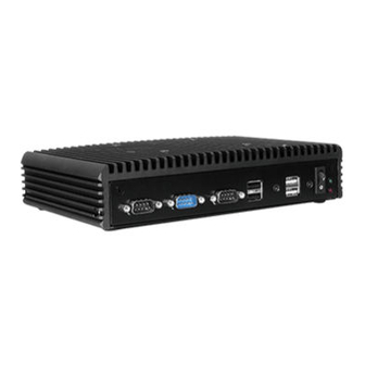
Page 21: 3.1 External System I/O Ports Diagrams
Chapter 3 Hardware Configuration 3.1 External System I/O Ports Diagrams 3.1.1 Front I/O Ports Diagram 3.1.2 Rear I/O Ports Diagram BS-E098 SERIES USER MANUAL Page: 3-2... -
Page 22: Jumper & Connector Quick Reference Table
2 x Dual USB 3.0 Ports (Rear) USB3.0 Dual USB2.0 Ports(Front) USB2.0 Optional Dual USB2.0 Ports(Front) USB2.0 Line-out connector (Rear) Line-out Onboard CONNECTOR NAME Description Programmable Digital I/O Pin JDIO1 Header I2C Wafer JI2C1 System Fan Connector FAN1 BS-E098 SERIES USER MANUAL Page: 3-3... -
Page 23: Component Locations Of System Main Board
JINV1 SATA 3.0 Connector SATA1 SATA Power Connector SATA_PWR1 BIOS Reset Connector COMPONENT LOCATIONS OF SYSTEM MAIN BOARD 3.3.1 Top View of System Main Board (BE-0981RA-**N) Figure 3-1 Main Board Component Location (Top View) BS-E098 SERIES USER MANUAL Page: 3-4... -
Page 24: Jumper Setting Of System Main Board (Be-0981Ra-**N)
Make sure both the system and peripheral devices are turned OFF as sudden surge of power could damage sensitive components. Make sure BS-E098 is properly grounded. CAUTION: Observe precautions while handling electrostatic sensitive components. Make sure to ground yourself to prevent static charge while you are working on the connectors and jumpers. -
Page 25: Bottom View Of System Main Board
Chapter 3 Hardware Configuration 3.3.3 Bottom View of System Main Board (BE-0981RA-N0N/ BE-0981RA-N1N) BS-E098 SERIES USER MANUAL Page: 3-6... -
Page 26: How To Set Jumpers
PIN1 & PIN2 to create one setting by shorting. You can either connect PIN2 & PIN3 to create another setting. The same jumper diagrams are applied all through this manual. The figure below shows what the manual diagrams look and what they represent. BS-E098 SERIES USER MANUAL Page: 3-7... -
Page 27: Jumper Settings
Jumper Block looks like this Jumper Settings 2 pin Jumper close(enabled) Looks like this 3 pin Jumper 2-3 pin close(enabled) Looks like this Jumper Block 1-2 pin close(enabled) Looks like this BS-E098 SERIES USER MANUAL Page: 3-8... -
Page 28: Setting Connectors And Jumpers
Setting Connectors and Jumpers 3.4.1 COM3 and COM4 PIN9 Definition Selection Guide JP_COM3, JP_COM4: COM3 and COM4 Port pin9 RI/5V/12V Selection SELECTION JUMPER SETTING JUMPER ILLUSTRATION (Default Setting) JP_COM3 JP_COM4 +12V JP_COM3 JP_ COM4 JP_ COM4 JP_COM3 BS-E098 SERIES USER MANUAL Page: 3-9... -
Page 29: Com Port
RS-485+ COM2 DTR# COM1 DSR# RTS# CTS# Notes: COM2 is selectable as RS-232, RS422, RS485 by BIOS setting. Default setting is RS-232. Please see Chapter 5 “Advanced – Onboard Device Configuration” for selection details. BS-E098 SERIES USER MANUAL Page: 3-10... - Page 30 CTS# COM4 DTR# Note: COM3, COM4: Pin 9 is selectable for RI, +5V or +12V by jumper setting. Default setting is RI, please see “COM3 and COM4 PIN9 Definition Selection Guide” for selection details. Page: 3-11 BS-E098 SERIES USER MANUAL...
-
Page 31: Dc-In 3 Pins Terminal Block
Description: Supports DC 12V power input (3 pins lockable terminal block) ASSIGNMENT +12V DC-IN 3.4.4 VGA PORT VGA1: VGA Port, D-Sub 15-pin (I/O port) VGA1 PIN ASSIGNMENT PIN ASSIGNMENT PIN ASSIGNMENT CRT_RED CRT_GREEN CRT_DATA CRT_BLUE CRT_HSYNC CRT_VCC CRT_VSYNC CRT_CLK BS-E098 SERIES USER MANUAL Page: 3-12... -
Page 32: Display Port
Chapter 3 Hardware Configuration 3.4.5 DISPLAY PORT DP1: Display Port Connector PIN ASSIGNMENT PIN ASSIGNMENT VCC3_PWR HPD_CON DP0_AUX_N_CON DP0_AUX_P_CON DP0_AUX_ENJ DP0_TX3_DN DP0_TX3_DP_C DP0_TX2_DN_C DP0_TX2_DP DP0_TX1_DN DP0_TX1_DP DP0_TX0_DN DP0_TX0_DP BS-E098 SERIES USER MANUAL Page: 3-13... -
Page 33: Lan Port
Status Description Right Side LED Yellow Blink LAN Message Active No LAN Message Active Left Side LED Green 10/100Mbps LAN connection is enabled. Orange Giga LAN connection is enabled. No LAN switch/hub is connected BS-E098 SERIES USER MANUAL Page: 3-14... -
Page 34: Dual Usb 3.0 Port (Usb1)
VCC5_USB1 3.4.8 USB 3.0 PORT (USB2) USB2: USB 3.0 port x 2 USB 3.0 signals PIN ASSIGNMENT PIN ASSIGNMENT USB3_RXN2 USB3_RXP2 USB2_P2_DP USB3_TXN2 USB2_P2_DN USB3_TXP2 VCC5_USB1 USB3_RXN1 USB2 USB3_RXP1 USB2_P1_DP USB3_TXN1 USB2_P1_DN USB3_TXP1 VCC5_USB1 BS-E098 SERIES USER MANUAL Page: 3-15... -
Page 35: Programmable Digital I/O Pin Header
Users can set the DIN/DOUT configuration via Protech’s API/Utility. Default setting is set as DIN every time when the system boots up. 3.4.10 I2C WAFER JI2C1: I2C Wafer PIN ASSIGNMENT VCC5 I2C0_SCL_33 I2C0_SDA_33 JI2C1 BS-E098 SERIES USER MANUAL Page: 3-16... -
Page 36: System Fan Connector
Default BIOS setting is “Auto Duty-Cycle Mode”. Please see Chapter 5 or check API document for more details. 3.4.12 DC POWER INPUT CONNECTOR PWR2: DC Power Input Connector PIN ASSIGNMENT PIN ASSIGNMENT VCC12 VCC12 PWR2 BS-E098 SERIES USER MANUAL Page: 3-17... -
Page 37: Mini Pci Express Slot
Mini PCI Express is the successor of the Mini PCI card and provides an increased data throughput. The cards have a detached network interface and are equipped with one lane. They are used in particular in embedded designs or compact box PCs. BS-E098 SERIES USER MANUAL Page: 3-18... -
Page 38: Msata Connector
Chapter 3 Hardware Configuration 3.4.14 mSATA Connector SLOT1: mSATA Slot (USB type mPCIe card is supported.) ASSIGNMENT ASSIGNMENT V3P3S_MSATA SATA_RXP1 V3P3S_MSATA SATA_RXN1 SLOT1 SATA_TXN1 SATA_TXP1 USB2_P0_DN USB2_P0_DP V3P3S_MSATA V3P3S_MSATA V3P3S_MSATA BS-E098 SERIES USER MANUAL Page: 3-19... -
Page 39: Lvds Connector
Chapter 3 Hardware Configuration 3.4.15 LVDS CONNECTOR LVDS1: LVDS Connector ASSIGNMENT ASSIGNMENT LVDS_VCC LVDS_CLKB_DP LVDS_CLKB_DN LVDS_B2_DN LVDS_B2_DP LVDS1 LVDS_B1_DP LVDS_B1_DN LVDS_B3_DN LVDS_B3_DP LVDS_B0_DN LVDS_B0_DP LVDS_CLKA_DP LVDS_CLKA_DN LVDS_A2_DN LVDS_A2_DP LVDS_A1_DP LVDS_A1_DN LVDS_A0_DN LVDS_A0_DP LVDS_A3_DN LVDS_A3_DP LVDS_VCC LVDS_VCC BS-E098 SERIES USER MANUAL Page: 3-20... -
Page 40: Front Panel Connector
HDD LED+ POWER LED+ HDD LED- JFP1 RESET BTN POWER BTN 3.4.17 HD AUDIO CONNECTOR AUDIO1: HD Audio Connector for Line_in/Line_out/Mic_in. ASSIGNMENT ASSIGNMENT LINE-OUT-L LINE-OUT-L HD_GND HD_GND HD_LINE-IN-R HD_LINE-IN-L HD_GND HD_GND HD_MIC1-R HD_MIC1-L AUDIO1 BS-E098 SERIES USER MANUAL Page: 3-21... -
Page 41: Panel Inverter Connector
JINV1: Panel Inverter Connector ASSIGNMENT VCC12 VCC12 JINV1 LVDS_BKLCTL LVDS_BKLTEN 3.4.19 SATA 3.0 CONNECTOR SATA1: Serial ATA 3.0 Connector ASSIGNMENT SATA_TXP0 SATA_TXN0 SATA1 SATA_RXN0 SATA_RXP0 SATA Power CONNECTOR 3.4.20 SATA_PWR1: Serial ATA Power Connector ASSIGNMENT VCC5 SATA_PWR1 BS-E098 SERIES USER MANUAL Page: 3-22... -
Page 42: Bios Reset Connector
JUMPER SETTING JUMPER ILLUSTRATION 3.3V (Default Setting) Note 1: Users can change the setting according to panel specification Note 2: Please refer to PANEL INVERTER CONNECTOR for more details about pin definition of JINV1. BS-E098 SERIES USER MANUAL Page: 3-23... -
Page 43: Lvds Vcc Voltage Selection
Description: Voltage selection jumper for selecting PIN1, PIN29, PIN30 (LVDS_VCC) voltage of LVDS1. JUMPTER SELECTION JUMPER ILLUSTRATION SETTING 3.3V (Default Setting) JP_VDD1 JP_VDD1 Note: Please refer to PANEL INVERTER CONNECTOR for more information about pin definition of JINV1. BS-E098 SERIES USER MANUAL Page: 3-24... -
Page 44: Clear Cmos Data Selection
Step3. Remove the cap which is just used on JP4 (1-2), so that JP4 returns to “OPEN”. Step4. Power on the PC and the PC will then auto-reboot for once in order to set SoC’s register. Step5. Done! SELECTION JUMPER SETTING JUMPER ILLUSTRATION Open Normal (Default Setting) Clear CMOS* BS-E098 SERIES USER MANUAL Page: 3-25... -
Page 45: Software Utilities
This chapter provides the detailed information that guides users to install driver utilities for the system. The following topics are included: • Installing Intel ® Chipset Software Installation Utility • Installing VGA Driver Utility • Installing LAN Driver Utility • Installing Sound Driver Utility... -
Page 46: Introduction
Chapter 4 Software Utilities Introduction Enclosed with the BS-E098 Series package is our driver utilities contained in a DVD-ROM disk. Refer to the following table for driver locations: Filename Win10 (Assume that DVD-ROM Purpose 64-bit drive is D:) D:\Driver\Flash BIOS For Aptio(EFI) BIOS update utility ... -
Page 47: Installing Intel Chipset Software Installation Utility
The Intel Chipset Software Installation Utility installs the Windows *.INF files to the target system. These files outline to the operating system how to configure the Intel chipset components in order to ensure that the following functions work properly: •... -
Page 48: Installing Vga Driver Utility
Chapter 4 Software Utilities Installing VGA Driver Utility The VGA interface embedded in BS-E098 can support a wide range of display types. You can have dual displays via LVDS interfaces and make the system work simultaneously. To install the VGA driver utility, follow the steps below: Connect the USB DVD-ROM device to BS-E098 and insert the driver disk. -
Page 49: Installing Lan Driver Utility
Enhanced with LAN function, BS-E098 supports various network adapters. To install the LAN Driver, follow the steps below: Connect the USB DVD-ROM device to BS-E098 and insert the driver disk. Enter the LAN folder where the driver is located (depending on your OS platform). -
Page 50: Installing Sound Driver Utility
The sound function enhanced in this system is fully compatible with Windows 10 64bit. To install the Sound Driver, follow the steps below: Connect the USB DVD-ROM device to BS-E098 and insert the driver disk. Open the Sound folder where the driver is located (depending on your OS platform). -
Page 51: Bios Setup
The BIOS Setup Utilities consist of the following menu items: • Accessing Setup Utilities • Main Menu • Advanced Menu • Chipset Menu • Boot Menu • Security Menu • Save & Exit Menu BS-E098 SERIES USER MANUAL Page: 5-1... -
Page 52: Introduction
Chapter 5 BIOS Setup Introduction The BS-E098 System uses an AMI (American Megatrends Incorporated) Aptio BIOS that is stored in the Serial Peripheral Interface Flash Memory (SPI Flash) and can be updated. The SPI Flash contains the built-in BIOS setup program, Power-On Self-Test (POST), PCI auto-configuration utility, LAN EEPROM information, and Plug and Play support. -
Page 53: Accessing Setup Utility
All the menu settings are described in details in this chapter. Accessing Setup Utility After the system is powered on, BIOS will enter the Power-On Self-Test (POST) routines and the POST message will be displayed: Figure 5-2. POST Screen with AMI Logo BS-E098 SERIES USER MANUAL Page: 5-3... - Page 54 English. You may use <↑> or <↓> key to select among the items and press <Enter> to confirm and enter the sub-menu. The following table provides the list of the navigation keys that you can use while operating the BIOS setup menu. BS-E098 SERIES USER MANUAL Page: 5-4...
- Page 55 The CMOS battery is The battery may be losing power and users should bad or has been recently replace the battery immediately. Also, this message is replaced. displayed once the new battery is replaced. BS-E098 SERIES USER MANUAL Page: 5-5...
-
Page 56: Main
No changeable options Displays the date that the current BIOS Time version is built. Access Level No changeable options Displays the current user access level. BXT SOC No changeable options Displays the SOC stepping. BS-E098 SERIES USER MANUAL Page: 5-6... - Page 57 The “Day” is automatically changed. System Time Hour, minute, second Sets the system time. The format is [Hour: Minute: Second]. Users can directly enter values or use <+> or <-> arrow keys to increase/decrease it. BS-E098 SERIES USER MANUAL Page: 5-7...
-
Page 58: Advanced
Sub-Menu Watchdog timer parameters. S5 RTC Wake Settings Sub-Menu RTC wake parameters. CPU Configuration Sub-Menu CPU configuration parameters. F81846 Super IO Sub-Menu System Super IO chip parameters Configuration USB Configuration Sub-Menu USB configuration parameters. BS-E098 SERIES USER MANUAL Page: 5-8... -
Page 59: Advanced - Acpi Settings
- Enabled (default) Hibernate (OS/S4 Sleep State). This option may be not effective with some OS. Enable Sleep (S3) - Disabled Enables or Disables System ability to Sleep - Enabled (default) (OS/S3 Sleep State). BS-E098 SERIES USER MANUAL Page: 5-9... -
Page 60: Advanced - Onboard Device Configuration
LAN SPI ROM - Disabled (default) Enables or disables LAN SPI ROM flash Flash - Enabled support by SPI ROM WP# pin. - RS-422 COM2 Mode - RS-232 (default) Selects COM2 mode. Selection - RS-485 BS-E098 SERIES USER MANUAL Page: 5-10... -
Page 61: Advanced - Hardware Monitor
Detects and displays 12V voltage. Detects and displays the voltage level VDDQ No changeable options of the VDDQ in supply. Detects and displays the voltage level VCC3V No changeable options of VCC3V in supply. BS-E098 SERIES USER MANUAL Page: 5-11... -
Page 62: Smart Fan Mode Configuration
System Fan Smart Fan -Manual Duty Mode Smart Fan Mode Select Control -Auto Duty-Cycle Mode When Auto Mode is specified, the fan (default) duty (speed) would increase or decrease linearly with the temperature by the rule below: BS-E098 SERIES USER MANUAL Page: 5-12... -
Page 63: Smart Fan Mode Configuration - [Manual Duty Mode]
Smart Fan Mode Configuration Screen BIOS Setting Options Description/Purpose Manual Duty Mode - 0% Manual mode fan control. Users can - 30% select expected duty cycle (PWM fan - 40% type). - 50% - 60% - 70% BS-E098 SERIES USER MANUAL Page: 5-13... -
Page 64: Advanced - F81846 Watchdog
BIOS Setting Options Description/Purpose - Disabled (default) Enables/Disables 81846 Watchdog Enable Watchdog - Enabled timer settings. Sets the timeout for Watchdog timer. Watchdog Timer Count (Numeric) 10 to 255 Watchdog Timer = 1sec * Count BS-E098 SERIES USER MANUAL Page: 5-14... -
Page 65: Advanced - S5 Rtc Wake Settings
- Fixed Time alarm event. • Fixed Time: The system will wake - Dynamic Time on the time (hr::min::sec) specified. • Dynamic Time: The system will wake on the current time + increased minute(s). BS-E098 SERIES USER MANUAL Page: 5-15... -
Page 66: S5 Rtc Wake Settings [Fixed Time]
(Numeric) from 0 to 23 power-on event. Sets a minute for a scheduled Wake up minute (Numeric)from 0 to 59 power-on event. Sets a second for a scheduled Wake up second (Numeric)from 0 to 59 power-on event. BS-E098 SERIES USER MANUAL Page: 5-16... -
Page 67: S5 Rtc Wake Settings [Dynamic Time]
S5 RTC Wake Setting Screen (Dynamic Time) BIOS Setting Options Description/Purpose Wake up minute increase (Numeric) from 1 to 5 Sets a period of time (in minutes) after which the board wakes up from S5 state. BS-E098 SERIES USER MANUAL Page: 5-17... -
Page 68: Advanced - Cpu Configuration
CPU power management options. - Disabled When enabled, a VMM can utilize the Intel Virtualization - Enabled (default) additional hardware capabilities Technology provided by Vanderpool Technology. - Disabled (default) VT-d Enables/Disables CPU VT-d. - Enabled BS-E098 SERIES USER MANUAL Page: 5-18... -
Page 69: Socket 0 Cpu Information
L1 Data Cache No changeable options L1 Data Cache Size. L1 Code Cache No changeable options L1 Code Cache Size. L2 Cache No changeable options L2 Cache Size. L3 Cache No changeable options L3 Cache Size. BS-E098 SERIES USER MANUAL Page: 5-19... -
Page 70: Cpu Power Management Configuration
CPU will switch to minimum speed when all cores enter C-State. Note: This item only work when "C-State" is enabled. Max Core C State - Fused This option controls the Max Core C BS-E098 SERIES USER MANUAL Page: 5-20... - Page 71 - Core C10 State that cores will support. - Core C9 Note: This item only work when - Core C8 "C-State" is enabled. - Core C7 - Core C6 (default) - Core C1 - Unlimited BS-E098 SERIES USER MANUAL Page: 5-21...
-
Page 72: Advanced - F81846 Super Io Configuration
No changeable options Displays the super I/O chip model. Serial Port 1 Configuration Sub-Menu COM1 parameters. Serial Port 2 Configuration Sub-Menu COM2 parameters. Serial Port 3 Configuration Sub-Menu COM3 parameters. Serial Port 4 Configuration Sub-Menu COM4 parameters. BS-E098 SERIES USER MANUAL Page: 5-22... -
Page 73: F81846 Super Io Configuration - Serial Port 1 Configuration
Allows users to change Device's - IO=3F8h; IRQ=4 Resource settings. New settings will - IO=3F8h; IRQ=3,4,5,7,9,10,11,12; be reflected on this Setup Page after - IO=2F8h; IRQ=3,4,5,7,9,10,11,12; System restarts. - IO=3E8h; IRQ=3,4,5,7,9,10,11,12; - IO=2E8h; IRQ=3,4,5,7,9,10,11,12; BS-E098 SERIES USER MANUAL Page: 5-23... -
Page 74: F81846 Super Io Configuration - Serial Port 2 Configuration
- Auto (default) Allows users to change Device's - IO=2F8h; IRQ=3 Resource settings. New settings will - IO=3F8h; IRQ=3,4,5,7,9,10,11,12; be reflected on this Setup Page after - IO=2F8h; IRQ=3,4,5,7,9,10,11,12; System restarts. -IO=3E8h; IRQ=3,4,5,7,9,10,11,12; -IO=2E8h; IRQ=3,4,5,7,9,10,11,12; BS-E098 SERIES USER MANUAL Page: 5-24... -
Page 75: F81846 Super Io Configuration - Serial Port 3 Configuration
- Auto (default) Allows users to change Device's - IO=3E8h; IRQ=7 Resource settings. New settings will - IO=3E8h; IRQ=3,4,5,7,9,10,11,12; be reflected on this Setup Page after - IO=2E8h; IRQ=3,4,5,7,9,10,11,12; System restarts. - IO=2F0h; IRQ=3,4,5,7,9,10,11,12; -IO=2E0h; IRQ=3,4,5,7,9,10,11,12; BS-E098 SERIES USER MANUAL Page: 5-25... -
Page 76: F81846 Super Io Configuration - Serial Port 4 Configuration
- Auto (default) Allows users to change Device's - IO=2E8h; IRQ=10 Resource settings. New settings will - IO=3E8h; IRQ=3,4,5,7,9,10,11,12; be reflected on this Setup Page after - IO=2E8h; IRQ=3,4,5,7,9,10,11,12; System restarts. -IO=2F0h; IRQ=3,4,5,7,9,10,11,12; -IO=2E0h; IRQ=3,4,5,7,9,10,11,12 BS-E098 SERIES USER MANUAL Page: 5-26... -
Page 77: Advanced - Usb Configuration
Legacy USB Support - Enabled (default) Enables Legacy USB support. AUTO - Disabled option disables legacy support if no - Auto USB devices are connected. DISABLED option will keep USB devices available only for EFI BS-E098 SERIES USER MANUAL Page: 5-27... - Page 78 DEVICES: [drive(s)] - Floppy to their media format. Optical drives - Forced FDD are emulated as 'CD-ROM'. Drives - Hard Disk with no media will be emulated - CD-ROM according to a drive type. BS-E098 SERIES USER MANUAL Page: 5-28...
-
Page 79: Chipset
This menu allows users to configure advanced Chipset settings such as North Bridge and South Bridge configuration parameters. Chipset Screen BIOS Setting Options Description/Purpose North Bridge Sub-menu North Bridge Parameters. South Bridge Sub-menu South Bridge Parameters. BS-E098 SERIES USER MANUAL Page: 5-29... -
Page 80: Chipset - North Bridge
Memory Speed No changeable options Displays memory speed. Memory Slot0 No changeable options Displays the current amount and type of memory on each memory slot, e.g. "8192 MB (LPDDR3)". LCD Control Sub-Menu LCD control parameters. BS-E098 SERIES USER MANUAL Page: 5-30... -
Page 81: North Bridge - Lcd Control
• If LVDS + DP are connected, the primary video device is DP and secondary is LVDS. • If LVDS + CRT + DP are connected, the primary video device is CRT and the secondary video device is DP. BS-E098 SERIES USER MANUAL Page: 5-31... -
Page 82: Chipset - South Bridge
Description/Purpose HD-Audio Configuration Sub-Menu HD-Audio configuration settings. LPSS Configuration Sub-Menu LPSS configuration settings. PCI Express Configuration Sub-Menu PCI Express configuration settings. SATA Drives Sub-Menu SATA Drives configuration settings. Miscellaneous Configuration Sub-Menu Miscellaneous configuration settings BS-E098 SERIES USER MANUAL Page: 5-32... -
Page 83: South Bridge - Hd-Audio Configuration
Chapter 5 BIOS Setup South Bridge - HD-Audio Configuration Menu Path Chipset > South Bridge > HD-Audio Configuration HD-Audio Configuration Screen BIOS Setting Options Description/Purpose - Disabled HD-Audio Support Enables/Disables HD-Audio support. - Enabled (default) BS-E098 SERIES USER MANUAL Page: 5-33... -
Page 84: South Bridge - Lpss Configuration
(D22:F0) - PCI Mode (default) support. - ACPI Mode Set LPSS I2C #1 Speed - Standard Mode Selects LPSS I2C #1 speed. - Fast Mode (default) - Fast Plus Mode - High Speed Mode BS-E098 SERIES USER MANUAL Page: 5-34... -
Page 85: South Bridge - Pci Express Configuration
PCI E Express Root Port 3 Sub-Menu PCIE RP3 parameters (LAN I210). PCI E Express Root Port 4 Sub-Menu PCIE RP4 parameters (LAN I210). PCI E Express Root Port 5 Sub-Menu PCIE RP5 parameters (Mini PCIe). BS-E098 SERIES USER MANUAL Page: 5-35... - Page 86 Options Description/Purpose PCI E Express Root Port 3 - Disable Enables/Disables PCIE root port 3 - Enable (LAN I210). - Auto (default) PCIe Speed - Auto (default) Configures PCIe speed. - Gen1 - Gen2 BS-E098 SERIES USER MANUAL Page: 5-36...
- Page 87 Options Description/Purpose PCI E Express Root Port 4 - Disable Enables/Disables PCIE root port 4 - Enable (LAN I210). - Auto (default) PCIe Speed - Auto (default) Configures PCIe speed. - Gen1 - Gen2 BS-E098 SERIES USER MANUAL Page: 5-37...
- Page 88 Options Description/Purpose PCI E Express Root Port 5 - Disable Enables/Disables PCIE root port 5 - Enable (Mini PCIe). - Auto (default) PCIe Speed - Auto (default) Configures PCIe speed. - Gen1 - Gen2 BS-E098 SERIES USER MANUAL Page: 5-38...
-
Page 89: South Bridge - Sata Drives
Enables/Disables SATA port 0. - Enabled (default) No changeable Displays SATA drive branding SATA Port 1 options information if device exists on port 1. - Disabled Port 1 Enables/Disables SATA port 1. - Enabled (default) BS-E098 SERIES USER MANUAL Page: 5-39... -
Page 90: South Bridge - Miscellaneous Configuration
Wake On Lan - Disable Enables or Disables the Wake On - Enable (default) LAN (WOL). Win 8/8.1/10 don't support WOL from hybrid shutdown state (S4). If you want to support WOL from BS-E098 SERIES USER MANUAL Page: 5-40... -
Page 91: Security
An administrator has much more privileges over the settings in the Setup utility than a user. Heed that a user password does not provide access to most of the features in the Setup utility. Security Screen BS-E098 SERIES USER MANUAL Page: 5-41... - Page 92 <Enter>, and the password dialog entry box appears. Select the configured Administrator Password or User Password that you want to delete. Leave the dialog box blank and press <Enter>. Press <Enter> again when the password confirmation box appears. BS-E098 SERIES USER MANUAL Page: 5-42...
-
Page 93: Boot
Bootup NumLock State - On (default) Selects the NumLock sate after the - Off system is powered on. • On: Enables the NumLock function automatically after the system is powered on. • Off: Disables the NumLock BS-E098 SERIES USER MANUAL Page: 5-43... -
Page 94: Boot - Csm Configuration
Boot - CSM Configuration Menu Path Boot > CSM Configuration The CSM Configuration provides advanced CSM (Compatibility Support Module) configurations such as Enable/Disable CSM Support, configure Option ROM execution, boot option filter, etc. CSM Configuration Screen BS-E098 SERIES USER MANUAL Page: 5-44... - Page 95 (UEFI OS, SHELL...). Network - Do not launch (default) Controls the execution of UEFI and - Legacy Legacy PXE OpROM. Note: This item only works when " CSM Support " is enabled. BS-E098 SERIES USER MANUAL Page: 5-45...
-
Page 96: Save & Exit
Discard Changes and Reset to discard any changes you have made and restore the factory BIOS defaults. Load User Defaults You may simply press F3 at any time to load the Optimized Values which resets all BIOS settings to the factory defaults. Save & Exit Screen BS-E098 SERIES USER MANUAL Page: 5-46... - Page 97 Save the changes done so far as User Save as User Defaults No changeable options Defaults. Restore the User Defaults to all the Restore User Defaults No changeable options setup options. Forces to boot from selected Boot Override - [Drive(s)] [drive(s)]. BS-E098 SERIES USER MANUAL Page: 5-47...
-
Page 98: Appendix A System Diagrams
Appendix A System Diagrams This appendix provides exploded diagrams and part numbers of BS-E098 system. The following topics are included: • BS-E098 System Exploded Diagram • BS-E098 SATA HDD Exploded Diagram Page: A-1 MH-5100 SERIES USER MANUAL... -
Page 99: Bs-E098 System Exploded Diagram
Appendix A System Diagrams BS-E098 System Exploded Diagram BS-E098 SERIES USER MANUAL Page: A-1... - Page 100 30-014-04100165 LED CABLE (2 IN 1) 23/26 27-019-39503071 POWER SWITCH CABLE 27-024-39505031 (x3) COM CABLE 27-024-39505032 (x1) USB *2 CABLE 27-006-39504111 POWER CABLE (DC IN to Daughter board) 27-012-39503071 L=160mm PHONE JACK CABLE 27-028-39503111 BS-E098 SERIES USER MANUAL Page: 2...
-
Page 101: Bs-E098 Sata Hdd Exploded Diagram
Appendix A System Diagrams BS-E098 SATA HDD Exploded Diagram BS-E098 SERIES USER MANUAL Page: A-3... - Page 102 Appendix A Technical Summary ITEM Description Part No. Q’ty BS-E981 HDD SUPPORT 80-002-03001395 RUBBER WASHER 23-680-39580963 (OD=φ9.62mm,ID=φ3.9mmx5.8T)(Blue) FILLISTR HEAD SCREW M3x0.5Px4.8mm 82-272-30005013 Thermal Interface Pads, 85x60x0.5mm 21-006-88560001 (Dark Gray) 2.5”_HDD_SATA 27-008-39503081 BS-E098 SERIES USER MANUAL Page: 4...
-
Page 103: Appendix B Technical Summary
Appendix A System Diagrams Appendix B Technical Summary This appendix will give you a brief introduction of the allocation maps for BS-E098 resources. The following topics are included: • Interrupt Map • I/O Map • Memory Map • Configuring WatchDog Timer •... -
Page 104: Interrupt Map
System CMOS/real time clock IRQ 10 Communications Port (COM4) IRQ 25 High Definition Audio Controller IRQ 27 Intel(R) Serial IO I2C Host Controller - 5AAC IRQ 54 Microsoft ACPI-Compliant System IRQ 55 Microsoft ACPI-Compliant System IRQ 56 Microsoft ACPI-Compliant System... - Page 105 IRQ 90 Microsoft ACPI-Compliant System IRQ 91 Microsoft ACPI-Compliant System IRQ 92 Microsoft ACPI-Compliant System IRQ 93 Microsoft ACPI-Compliant System IRQ 94 Microsoft ACPI-Compliant System IRQ 95 Microsoft ACPI-Compliant System IRQ 96 Microsoft ACPI-Compliant System BS-E098 SERIES USER MANUAL Page: B-3...
- Page 106 IRQ 117 Microsoft ACPI-Compliant System IRQ 118 Microsoft ACPI-Compliant System IRQ 119 Microsoft ACPI-Compliant System IRQ 120 Microsoft ACPI-Compliant System IRQ 121 Microsoft ACPI-Compliant System IRQ 122 Microsoft ACPI-Compliant System IRQ 123 Microsoft ACPI-Compliant System BS-E098 SERIES USER MANUAL Page: B-4...
- Page 107 IRQ 144 Microsoft ACPI-Compliant System IRQ 145 Microsoft ACPI-Compliant System IRQ 146 Microsoft ACPI-Compliant System IRQ 147 Microsoft ACPI-Compliant System IRQ 148 Microsoft ACPI-Compliant System IRQ 149 Microsoft ACPI-Compliant System IRQ 150 Microsoft ACPI-Compliant System BS-E098 SERIES USER MANUAL Page: B-5...
- Page 108 IRQ 171 Microsoft ACPI-Compliant System IRQ 172 Microsoft ACPI-Compliant System IRQ 173 Microsoft ACPI-Compliant System IRQ 174 Microsoft ACPI-Compliant System IRQ 175 Microsoft ACPI-Compliant System IRQ 176 Microsoft ACPI-Compliant System IRQ 177 Microsoft ACPI-Compliant System BS-E098 SERIES USER MANUAL Page: B-6...
- Page 109 IRQ 198 Microsoft ACPI-Compliant System IRQ 199 Microsoft ACPI-Compliant System IRQ 200 Microsoft ACPI-Compliant System IRQ 201 Microsoft ACPI-Compliant System IRQ 202 Microsoft ACPI-Compliant System IRQ 203 Microsoft ACPI-Compliant System IRQ 204 Microsoft ACPI-Compliant System BS-E098 SERIES USER MANUAL Page: B-7...
- Page 110 IRQ 276 Microsoft ACPI-Compliant System IRQ 277 Microsoft ACPI-Compliant System IRQ 278 Microsoft ACPI-Compliant System IRQ 279 Microsoft ACPI-Compliant System IRQ 280 Microsoft ACPI-Compliant System IRQ 281 Microsoft ACPI-Compliant System IRQ 282 Microsoft ACPI-Compliant System BS-E098 SERIES USER MANUAL Page: B-8...
- Page 111 IRQ 303 Microsoft ACPI-Compliant System IRQ 304 Microsoft ACPI-Compliant System IRQ 305 Microsoft ACPI-Compliant System IRQ 306 Microsoft ACPI-Compliant System IRQ 307 Microsoft ACPI-Compliant System IRQ 308 Microsoft ACPI-Compliant System IRQ 309 Microsoft ACPI-Compliant System BS-E098 SERIES USER MANUAL Page: B-9...
- Page 112 IRQ 330 Microsoft ACPI-Compliant System IRQ 331 Microsoft ACPI-Compliant System IRQ 332 Microsoft ACPI-Compliant System IRQ 333 Microsoft ACPI-Compliant System IRQ 334 Microsoft ACPI-Compliant System IRQ 335 Microsoft ACPI-Compliant System IRQ 336 Microsoft ACPI-Compliant System BS-E098 SERIES USER MANUAL Page: B-10...
- Page 113 IRQ 357 Microsoft ACPI-Compliant System IRQ 358 Microsoft ACPI-Compliant System IRQ 359 Microsoft ACPI-Compliant System IRQ 360 Microsoft ACPI-Compliant System IRQ 361 Microsoft ACPI-Compliant System IRQ 362 Microsoft ACPI-Compliant System IRQ 363 Microsoft ACPI-Compliant System BS-E098 SERIES USER MANUAL Page: B-11...
- Page 114 IRQ 384 Microsoft ACPI-Compliant System IRQ 385 Microsoft ACPI-Compliant System IRQ 386 Microsoft ACPI-Compliant System IRQ 387 Microsoft ACPI-Compliant System IRQ 388 Microsoft ACPI-Compliant System IRQ 389 Microsoft ACPI-Compliant System IRQ 390 Microsoft ACPI-Compliant System BS-E098 SERIES USER MANUAL Page: B-12...
- Page 115 IRQ 411 Microsoft ACPI-Compliant System IRQ 412 Microsoft ACPI-Compliant System IRQ 413 Microsoft ACPI-Compliant System IRQ 414 Microsoft ACPI-Compliant System IRQ 415 Microsoft ACPI-Compliant System IRQ 416 Microsoft ACPI-Compliant System IRQ 417 Microsoft ACPI-Compliant System BS-E098 SERIES USER MANUAL Page: B-13...
- Page 116 IRQ 438 Microsoft ACPI-Compliant System IRQ 439 Microsoft ACPI-Compliant System IRQ 440 Microsoft ACPI-Compliant System IRQ 441 Microsoft ACPI-Compliant System IRQ 442 Microsoft ACPI-Compliant System IRQ 443 Microsoft ACPI-Compliant System IRQ 444 Microsoft ACPI-Compliant System BS-E098 SERIES USER MANUAL Page: B-14...
- Page 117 IRQ 465 Microsoft ACPI-Compliant System IRQ 466 Microsoft ACPI-Compliant System IRQ 467 Microsoft ACPI-Compliant System IRQ 468 Microsoft ACPI-Compliant System IRQ 469 Microsoft ACPI-Compliant System IRQ 470 Microsoft ACPI-Compliant System IRQ 471 Microsoft ACPI-Compliant System BS-E098 SERIES USER MANUAL Page: B-15...
- Page 118 IRQ 492 Microsoft ACPI-Compliant System IRQ 493 Microsoft ACPI-Compliant System IRQ 494 Microsoft ACPI-Compliant System IRQ 495 Microsoft ACPI-Compliant System IRQ 496 Microsoft ACPI-Compliant System IRQ 497 Microsoft ACPI-Compliant System IRQ 498 Microsoft ACPI-Compliant System BS-E098 SERIES USER MANUAL Page: B-16...
- Page 119 IRQ 509 Microsoft ACPI-Compliant System IRQ 510 Microsoft ACPI-Compliant System IRQ 511 Microsoft ACPI-Compliant System Intel(R) I210 Gigabit Network Connection #2 4294967277 Intel(R) I210 Gigabit Network Connection #2 4294967278 Intel(R) I210 Gigabit Network Connection #2 4294967279 Intel(R) I210 Gigabit Network Connection #2...
- Page 120 4294967285 Intel(R) I210 Gigabit Network Connection 4294967286 Intel(R) I210 Gigabit Network Connection 4294967287 Intel(R) I210 Gigabit Network Connection 4294967288 Intel(R) USB 3.0 eXtensible Host Controller - 1.0 4294967289 (Microsoft) Intel(R) Trusted Execution Engine Interface 4294967290 Intel(R) HD Graphics 4294967291 Standard SATA AHCI Controller...
-
Page 121: I/O Map
Motherboard resources 0x00000065-0x00000065 Motherboard resources 0x00000067-0x00000067 Motherboard resources 0x00000070-0x00000070 Motherboard resources 0x00000070-0x00000070 System CMOS/real time clock 0x00000078-0x00000CF7 PCI Express Root Complex 0x00000080-0x0000008F Motherboard resources 0x00000092-0x00000092 Motherboard resources 0x000000A0-0x000000A1 Programmable interrupt controller 0x000000A4-0x000000A5 Programmable interrupt controller BS-E098 SERIES USER MANUAL Page: B-19... - Page 122 PCI Express Root Complex 0x0000164E-0x0000164F Motherboard resources 0x0000D000-0x0000DFFF Intel(R) Celeron(R)/Pentium(R) Processor PCI Express Root Port - 5AD9 0x0000E000-0x0000EFFF Intel(R) Celeron(R)/Pentium(R) Processor PCI Express Root Port - 5AD8 0x0000F000-0x0000F03F Intel(R) HD Graphics 0x0000F040-0x0000F05F Intel(R) Celeron(R)/Pentium(R) Processor BS-E098 SERIES USER MANUAL Page: B-20...
-
Page 123: Memory Map
0xFED08000-0xFED09FFF Motherboard resources 0xFED80000-0xFEDBFFFF Motherboard resources 0xFED1C000-0xFED1CFFF Motherboard resources 0xFEE00000-0xFEEFFFFF Motherboard resources 0x91300000-0x9130FFFF Intel(R) USB 3.0 eXtensible Host Controller - 1.0 (Microsoft) 0x91280000-0x912FFFFF Intel(R) I210 Gigabit Network Connection #2 0x9127C000-0x9127FFFF Intel(R) I210 Gigabit Network Connection #2 0x91180000-0x911FFFFF Intel(R) I210 Gigabit Network... - Page 124 0x91316000-0x913160FF Intel(R) Celeron(R)/Pentium(R) Processor SMBUS - 5AD4 0x91100000-0x911FFFFF Intel(R) Celeron(R)/Pentium(R) Processor PCI Express Root Port - 5AD9 0x91318000-0x91318FFF Intel(R) Serial IO I2C Host Controller - 5AAC 0x91317000-0x91317FFF Intel(R) Serial IO I2C Host Controller - 5AAC 0x7B800001-0x7BFFFFFF PCI Express Root Complex...
-
Page 125: Configuring Watchdog Timer
To exit the Extended Function Mode, writing 0xAA to the EFER is required. Once the chip exits the Extended Function Mode, it is in the normal running mode and is ready to enter the configuration mode. BS-E098 SERIES USER MANUAL Page: B-23... - Page 126 ;---------------------------------Enable Watch dog feature ------------------------------ dx, al dx, al ; ---------------- Set timeout interval as 30seconds and start counting -------------- dx, al dx, al ;------------------------------- Enable Watch PME-------------------------------------------- dx, al BS-E098 SERIES USER MANUAL Page: B-24...
- Page 127 Appendix B Technical Summary dx, al ;-------------------------- Set second as counting unit -------------------------------------- dx, al dx, al ;-------------------------- Start the watchdog timer -------------------------------------- dx, al ;---------------------------------Exit the extended function mode ------------------------- dx, al BS-E098 SERIES USER MANUAL Page: B-25...
-
Page 128: Flash Bios Update
(4) Select [Boot] menu. (5) Select [Hard Drive BBS Priorities] and set the USB bootable device as the 1st boot device. (6) Press F4 to save the configuration and exit the BIOS setup menu. BS-E098 SERIES USER MANUAL Page: B-26... - Page 129 ?” to see all the definition of each control options. The recommended options for BIOS ROM update include following parameters: Program main BIOS image. /B: Program Boot Block. /N: Program NVRAM. /X: Don’t check ROM ID. BS-E098 SERIES USER MANUAL Page: B-27...
- Page 130 Restart the system and boot up with the new BIOS configurations. The BIO Update is completed after the system is restarted. Reboot the system and verify if the BIOS version shown on the initialization screen has been updated. BS-E098 SERIES USER MANUAL Page: B-28...
- Page 131 Appendix B Technical Summary BS-E098 SERIES USER MANUAL Page: B-29...
Need help?
Do you have a question about the BS-E098 and is the answer not in the manual?
Questions and answers