Table of Contents
Advertisement
Advertisement
Table of Contents

Related Manuals for Fluke DSP-FTA420


Summary of Contents for Fluke DSP-FTA420
- Page 1 ® Advanced Test Equipment Rentals www.atecorp.com 800-404-ATEC (2832) DSP-FTA420/30/40 Fiber Test Adapter Users Manual English PN 1570398 July 2000 © 2000 Fluke Networks. All rights reserved. Printed in U.S.A. All product names are trademarks of their respective companies.
- Page 2 Fluke’s warranty obligation is limited, at Fluke’s option, to refund of the purchase price, free of charge repair, or replacement of a defective product which is returned to a Fluke authorized service center within the warranty period.
-
Page 3: Table Of Contents
Table of Contents Title Page Introduction ..................1 Unpacking .................... 2 Safety Information................3 Fiber Test Adapter Features ..............4 Getting Started..................5 Cleaning the Fiber Connections ............6 Verifying Operation................6 Summary of Fiber Test Settings ............8 Setting Up for Fiber Tests ..............9 Selecting a Test Standard and Fiber Type ........ - Page 4 Configuring a Custom Fiber Test............38 Fiber Test Reports................. 39 Maintenance..................39 Calibration ..................40 Repair....................40 Contacting Fluke Networks ..............40 Replacement Parts and Accessories ............40 Specifications..................42 General Specifications ..............42 Optical Transmitter ................42 Optical Receiver................43 Fiber Troubleshooting Guide..............
- Page 5 List of Tables Table Title Page Settings for Testing Fiber..............8 Loss Results for Smart Remote Mode..........23 Length Results for Smart Remote Mode..........24 Loss Results for Loopback Mode ............27 Length Results for Loopback Mode........... 27 Loss Results for Far End Source Mode ..........29 Main Unit Results for the FindFiber Test (Smart Remote Mode ..
- Page 6 Contents (continued)
-
Page 7: List Of Figures
List of Figures Figure Title Page Standard Equipment................2 Features of the DSP-FTA4XX Fiber Test Adapter ......4 Attaching a DSP-FTA4XX ..............5 Connections for a Self Test..............7 Setting a Reference for Smart Remote Mode........13 Setting a Reference for Loopback Testing ......... 14 Setting a Reference for Far End Source Mode........ - Page 8 Contents (continued)
-
Page 9: Introduction
Introduction The DSP-FTA420/30/40 Fiber Test Adapters (hereafter referred to as the DSP- FTA4XX) lets you use a DSP-4000 CableAnalyzer™ test tool to test and certify fiber optic cable installations. The fiber test adapter includes the following features: • Autotest function measures optical power loss and length on dual-fiber multimode (DSP-FTA420/440) and singlemode (DSP-FTA430) links. -
Page 10: Unpacking
DSP-FTA420/30/40 Users Manual Unpacking The DSP-FTA4XXS Fiber Test Option Set includes the following items, which are shown in Figure 1: • Two DSP-FTA4XX Fiber Test Adapters • Two ST/ST adapters • Four SC/ST patch cords FTA-420 – 62.5 µm multimode FTA-430 - singlemode FTA-440 –... -
Page 11: Safety Information
Fiber Test Adapter Safety Information Safety Information *W Warning To avoid possible eye damage caused by hazardous radiation: • Never look directly into optical output connectors (see Figure 2). Some sources produce invisible radiation that can permanently damage your eyes. •... -
Page 12: Fiber Test Adapter Features
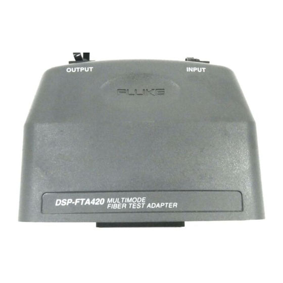
DSP-FTA420/30/40 Users Manual Fiber Test Adapter Features Figure 2 describes the features of the DSP-FTA4XX Fiber Test Adapter. OUTPUT INPUT agp11f.eps SC output connector. Transmits multimode or singlemode optical signals. SC input connector. Receives multimode or singlemode optical signals. DB60 connector and latches for attaching the DSP-FTA4XX unit to a DSP-4000 test tool. -
Page 13: Getting Started
Fiber Test Adapter Getting Started Getting Started This section describes how to connect the DSP-FTA4XX units and verify their operation. Attach a DSP-FTA4XX unit to your DSP-4000 test tool, as shown in Figure 3. Attach the matching DSP-FTA4XX unit to the DSP-4000 remote unit. The DSP-FTA4XX units with the same model number are identical, so either one can be attached to the remote. -
Page 14: Cleaning The Fiber Connections
Run the self test from the test tool’s SPECIAL FUNCTIONS mode. If the self test fails, verify that your patch cords are good, clean the fiber endfaces; then run the self test again. If it continues to fail, contact Fluke Networks as described under "Contacting Fluke Networks". - Page 15 Fiber Test Adapter Getting Started Patch cords of the same type as the fiber to be tested and SC at test tool ends Adapters OUTPUT INPUT OUTPUT INPUT DSP-4000 SMART REMOTE DSP-4000 CABLE ANALYZER PASS TESTING FAIL Test tool Remote TALKING LOW BATTERY with fiber test...
-
Page 16: Summary Of Fiber Test Settings
Smart Remote Mode uses a pair of DSP-FTA4XX units. Loopback Mode uses one DSP-FTA4XX unit. Far End Source Mode requires a separate optical source, such as the Fluke FOS-850/1300, FS-150 multimode sources or the Fluke LS-1310/1550 laser source. Figures 8, 9, and 10 show the three configurations. -
Page 17: Setting Up For Fiber Tests
DSP-4000 software upgrades available from Fluke. Refer to the DSP-4000 Users Manual for information on upgrades or contact Fluke Networks on the World Wide Web at www.flukenetworks.com. Select a fiber test standard and cable type as follows: Attach a DSP-FTA4XX unit to the DSP-4000 test tool. -
Page 18: Setting The Remote End Configuration
• Far End Source Mode is used with a laser source, such as the Fluke LS-1310/1550 Laser Source, to test singlemode fiber. You can also use Far End Source Mode with a separate multimode source, such as the Fluke FOS-850/1300 Fiber Optic Source. (Refer to Figure 10.) -
Page 19: Setting The Number Of Adapters And Splices
Fiber Test Adapter Setting Up for Fiber Tests Setting the Number of Adapters and Splices Some test standards use a calculated limit for the loss test. This limit includes the number of adapters and splices in the link. In the test tool’s SETUP mode, enter the number of adapters and number of splices added in each direction of the fiber path since the reference was set. -
Page 20: Setting A Reference For Smart Remote Mode
DSP-FTA420/30/40 Users Manual Setting a Reference for Smart Remote Mode Turn on the test tool and the remote. Let the DSP-FTA4XX units warm up for five minutes. Set the remote end configuration to Smart Remote Mode. Choose four known-good SC/ST patch cords of fiber type matching the cables to be tested, e.g., 50 µm multimode;... - Page 21 Fiber Test Adapter Setting Up for Fiber Tests Patch cords of the same type as the fiber to be tested and SC at test tool ends Adapters OUTPUT INPUT OUTPUT INPUT DSP-4000 SMART REMOTE DSP-4000 CABLE ANALYZER PASS TESTING FAIL Test tool Remote TALKING...
-
Page 22: Setting A Reference For Loopback Mode
DSP-FTA420/30/40 Users Manual Setting a Reference for Loopback Mode Turn on the test tool. Let the DSP-FTA4XX units warm up for five minutes. Set the remote end configuration to Loopback Mode. Choose two known-good SC/ST patch cords of fiber type matching the cables to be tested, e.g., 50 µm multimode;... -
Page 23: Setting A Reference For Far End Source Mode
OUTPUT INPUT 1310 OFF 1550 CAUTION SOURCE ACTIVE LOW BATTERY DSP-4000 CABLE ANALYZER Test tool Optical source with fiber test (such as adapter Fluke LS-1310/1550 EXIT LS-1310/1550 LASER SOURCE FAULT or FOS-850/1300) TALK INFO SAVE TEST ENTER MONITOR SINGLE SETUP... -
Page 24: Changing The Index Of Refraction
You can also use the Autotest in Far End Source Mode to measure loss on a single fiber. Using Autotest, rather than a Single Test, gives the option of saving the test results. If you use an optional multimode source, such as the Fluke FOS-850/1300 source, Autotest measures optical power loss only. - Page 25 Fiber Test Adapter Running an Autotest Run an Autotest as follows: Turn the test tool’s rotary switch to AUTOTEST and turn on the remote (if used). Let the DSP-FTA4XX units warm up for five minutes. Verify that the Autotest display shows the correct test standard, cable type, and remote end configuration.
- Page 26 DSP-FTA420/30/40 Users Manual Optical patch cord Fiber Link Optical patch cords Optical patch cords (SC at test tool ends) (SC at test tool ends) OUTPUT INPUT OUTPUT INPUT Optical Connections DSP-4000 SMART REMOTE DSP-4000 CABLE ANALYZER PASS TESTING FAIL TALKING...
- Page 27 Fiber Test Adapter Running an Autotest Optical patch cord Optical patch cords (SC at test tool ends) Fiber under test OUTPUT INPUT Optical Connections DSP-4000 CABLE ANALYZER EXIT FAULT TALK INFO Test tool SAVE TEST ENTER MONITOR SINGLE with fiber test SETUP TEST AUTO...
- Page 28 DSP-FTA420/30/40 Users Manual Optical patch cord Fiber link Optical patch cord Optical patch cord (SC at test tool end) OUTPUT INPUT Optical connections 1310 OFF 1550 CAUTION SOURCE ACTIVE LOW BATTERY DSP-4000 CABLE ANALYZER Test tool Optional laser with fiber test...
-
Page 29: Saving Autotest Results
Fiber Test Adapter Saving Autotest Results Saving Autotest Results To save the results of the last Autotest, press S. Use the test tool’s alphanumeric display to enter one or two fiber names, depending on which remote end configuration was used: •... -
Page 30: Autotest Results For Smart Remote Mode
DSP-FTA420/30/40 Users Manual Autotest Results for Smart Remote Mode This section describes the DSP-FTA4XX fiber tests and the results produced when you run an Autotest using Smart Remote Mode. The descriptions of loss and length tests also apply to Single Tests using Smart Remote Mode. -
Page 31: Loss Results For Smart Remote Mode
Fiber Test Adapter Autotest Results for Smart Remote Mode Table 2. Loss Results for Smart Remote Mode Result Description Fiber The fiber (output or input) that corresponds to the test results. If bi-directional testing is enabled, the output fiber is the fiber you connected to the output port of the main unit after swapping the fibers. -
Page 32: Length Results For Smart Remote Mode
DSP-FTA420/30/40 Users Manual Length Results for Smart Remote Mode The test tool determines fiber length by measuring the propagation delay through the fiber, then using the index of refraction to calculate the length. Table 3 describes the length results for Smart Remote Mode. -
Page 33: Bi-Directional Testing
Fiber Test Adapter Bi-Directional Testing Bi-Directional Testing When you need to test fibers in both directions, the DSP-FTA4XX units can perform bi-directional testing and save the bi-directional results for each fiber. You enable this feature in the SETUP mode under BI-DIRECTIONAL TEST. -
Page 34: Autotest Results For Loopback Mode
DSP-FTA420/30/40 Users Manual Autotest Results for Loopback Mode This section describes the Autotest results for Loopback Mode. The descriptions of loss, length, and propagation delay tests also apply to Single Tests using Loopback Mode. To see the complete results for a test, press ! View Result on the first Autotest display, use D to highlight the desired test, then press E. -
Page 35: Length Results For Loopback Mode
Fiber Test Adapter Autotest Results for Loopback Mode Table 4. Loss Results for Loopback Mode Result Description Result PASS - the power loss is less than allowed for the link. FAIL- the loss exceeded the limit. Loss (dB) The combined loss of all fibers in the link under test. -
Page 36: Autotest Results For Far End Source Mode
DSP-FTA420/30/40 Users Manual Autotest Results for Far End Source Mode An Autotest using Far End Source Mode measures loss for singlemode or multimode fibers. The Autotest runs continuously until the e key is pressed. Table 6 describes the results. The results display also features softkeys that are available only for Far End Source Mode: •... -
Page 37: Loss Results For Far End Source Mode
Fiber Test Adapter Autotest Results for Far End Source Mode Table 6. Loss Results for Far End Source Mode Result Description PASS/FAIL Pass means the power loss is less than allowed by the limit. Fail means the loss exceeded the limit. Loss (dB) The measured optical power loss. -
Page 38: Single Tests
DSP-FTA420/30/40 Users Manual Single Tests The SINGLE TEST mode on the DSP-4000 rotary switch lets you run individual fiber tests. Single Tests are useful for quick checks of continuity, length, or loss, and for isolating faults and testing repairs. Single Tests run continuously, so you can make adjustments to a link and watch the results as they happen. -
Page 39: Single Tests For Loopback Mode
Fiber Test Adapter Single Tests Single Tests for Loopback Mode Use these tests to troubleshoot fiber links, test patch cords, and check spools of fiber before installation. • Total Loss: Measures the optical power loss between the output and input ports of the DSP-FTA4XX unit. If two fibers are connected end-to- end with a loopback cable, the total loss of both fibers is displayed. -
Page 40: Monitoring Optical Power
DSP-FTA420/30/40 Users Manual Monitoring Optical Power You can use the MONITOR position of the DSP-4000 rotary switch to monitor the output power produced by a source such as an optical network interface card or optical test equipment. You can also monitor the power received at the end of a fiber link. - Page 41 Fiber Test Adapter Monitoring Optical Power Optical patch cord (SC at test tool end) OUTPUT INPUT OUTPUT DSP-4000 CABLE ANALYZER Test tool with fiber test Optical network interface card adapter or optical power source EXIT FAULT TALK INFO TEST ENTER SAVE MONITOR SINGLE...
-
Page 42: Using The Talk Mode
DSP-FTA420/30/40 Users Manual Using the Talk Mode With a pair of DSP- FTA4XX Fiber Test Adapters, you can use the DSP-4000 headsets for two-way voice communication over the two fibers under test. To use the Talk mode, connect the main and remote units for Smart Remote Mode, then press V on either unit. - Page 43 Fiber Test Adapter Using the FindFiber™ Feature For Loopback Mode, try various connections with the main unit’s INPUT fiber until the Receiving Near End result shows PASS. Table 7. Main Unit Results for the FindFiber Test (Smart Remote Mode) Results Description Receiving Near End: FAIL...
- Page 44 DSP-FTA420/30/40 Users Manual Fiber Link OUTPUT INPUT OUTPUT INPUT DSP-4000 SMART REMOTE DSP-4000 CABLE ANALYZER PASS TESTING FAIL TALKING LOW BATTERY EXIT Remote TALK FAULT Test tool TALK INFO TEST ENTER SAVE with fiber test MONITOR with fiber test SINGLE...
- Page 45 Fiber Test Adapter Using the FindFiber™ Feature Fiber Link OUTPUT INPUT DSP-4000 CABLE ANALYZER EXIT FAULT Test tool TALK INFO TEST ENTER SAVE MONITOR with fiber test SINGLE SETUP TEST AUTO PRINT TEST adapter SPECIAL FUNCTIONS agp13f.eps Figure 13. Using FindFiber with a Loopback Cable...
-
Page 46: Configuring A Custom Fiber Test
DSP-FTA420/30/40 Users Manual Configuring a Custom Fiber Test In some cases, you might want to create your own custom test, rather than use the standard tests stored in your test tool. The test tool’s Configure Custom Test function lets you define up to four custom fiber standards. -
Page 47: Fiber Test Reports
Fiber Test Adapter Fiber Test Reports Configure a Custom Test as follows: On the last page of the SETUP mode, CONFIGURE CUSTOM TEST, select a Custom Cable from the list; then press E. If you want to edit the name of the custom test, press E; then use the alphanumeric display to enter a new name. -
Page 48: Calibration
Repair If a DSP-FTA4XX unit requires service, pack it in the original shipping container and send it, postage paid and insured, to the nearest Fluke Service Center. Include a written description of the problem. Fluke assumes no responsibility for shipping damage. Refer to the warranty for warranty repair terms. -
Page 49: Replacement Parts And Accessories
Fiber Jack Accessory Kit, 62.5 um, multimode NFK1-FJ 850/1300 Multimode Fiber Optic Source FS-150 LS-1310/1550 Singlemode Laser Source LS-1310/1550 FOS-850/1300 Multimode Fiber Optic Source FOS-850/1300 DSP-FTA420/30/40 Users Manual, English 1570398 DSP-FTA420/30/40 Users Manual, French 1570405 DSP-FTA420/30/40 Users Manual, Spanish 1570431 DSP-FTA420/30/40 Users Manual, Italian 1570410... -
Page 50: Specifications
DSP-FTA420/30/40 Users Manual Specifications General Specifications Power supply: ±6 V supplied by the DSP-4000 test tool. Temperature range: Operating: 0 ºC to +40 ºC; Storage: -10 ºC to +60 ºC Warm-up time: 5 minutes Humidity range: Operating: 0 % to 75 % RH, non-condensing... -
Page 51: Optical Receiver
Fiber Test Adapter Specifications Optical Receiver Power measurement accuracy: ±0.25 dBm at 23 °C, 45 % RH to 75 % RH, -20 dBm for 850 nm and 1300 nm, -10 dBm for 1550 and 1625 nm Connector: SC, multimode or singlemode Detector type: InGaAs Calibrated wavelengths: 850 nm, 1300 nm, 1310 nm, 1550 and 1625 nm. - Page 52 DSP-FTA420/30/40 Users Manual...
-
Page 53: Fiber Troubleshooting Guide
Appendix A Fiber Troubleshooting Guide Table 10 on the next page lists some common problems in fiber links and gives possible causes. -
Page 54: Common Problems In Fiber Links
DSP-FTA420/30/40 Users Manual Table 10. Common Problems in Fiber Links Problem Possible Causes No power is The optical source is defective. measured at a source The patch cord is defective. Power loss is much The fibers are connected to the wrong ports on a more than expected DSP-FTA4XX unit. -
Page 55: Glossary
Appendix B Glossary Adapter A device used to mate fiber connectors of the same or different styles. Attenuation A loss of optical power, mostly due to poor connections or to light diffusion caused by imperfections in the fiber material (scattering). Bandwidth The range of frequencies a fiber can transmit without significant power loss. - Page 56 DSP-FTA420/30/40 Users Manual A unit of power (in decibels), assuming a reference of 1 mW (1/1000 of a watt). The dBm unit expresses loss or gain as a ratio of output power to the reference power, as follows: ...
- Page 57 Glossary Margin The difference between the measured power loss and the maximum loss allowed for the link. Microbending losses Light losses due to microscopic imperfections in a fiber. Multimode fiber Fiber with a relatively large core (50 µm or more) that offers many paths, or modes, for propagation of light.
- Page 58 DSP-FTA420/30/40 Users Manual SC connector Subscription Channel Connector. An optical connector that originated in Japan and provides push-pull connections, low loss, and low backreflection. Singlemode fiber Fiber with a small core (8 µm to 10 µm) that offers just one path, or mode, for propagation of light.
-
Page 59: Index
Loopback Mode connections, 19 when to use, 10 Loopback Mode results, 26 fiber type, selecting, 9 running, 16 FindFiber, 35 saving results, 21 Fluke Networks, contacting, 40 Smart Remote Mode connections, —G— Smart Remote Mode results, 21 glossary, 45 —B— —H—... - Page 60 Loopback Mode, 28 testing the DSP-FTA4XX, 6 Smart Remote Mode, 24 —V— —R— voice communications, 34 reference, 11 volume for talk mode, 34 Loopback Mode, 14 —W— Smart Remote Mode, 12 remote end configuration website, Fluke Networks, 40 which to use, 10...
Need help?
Do you have a question about the DSP-FTA420 and is the answer not in the manual?
Questions and answers