Advertisement
Quick Links
Download this manual
See also:
Instruction Manual
Instruction Manual
246
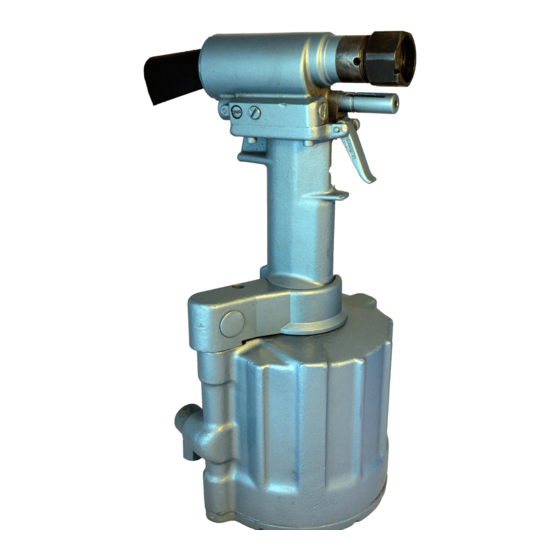
Pneudraulic Installation Tool
Patent Pending
Declaration of Conformity
Disassembly Instructions
Makers of Huck
January 27, 2017
Brand Fasteners, Tools & Accessories
HK825
Assembly Instructions
Components Drawings
14-15
Kits and Accessories
Troubleshooting
, Marson
, Recoil
®
®
2
3
4
5
6
7
8
9-10
11
12-13
16
16
®
Advertisement

Subscribe to Our Youtube Channel
Related Manuals for Huck 246


Summary of Contents for Huck 246
-
Page 1: Table Of Contents
Patent Pending Maintenance Operating Instructions Disassembly Instructions 9-10 Assembly Instructions Fill and Bleed 12-13 Components Drawings 14-15 Kits and Accessories Troubleshooting Makers of Huck , Marson , Recoil January 27, 2017 ® ® ® Brand Fasteners, Tools & Accessories HK825... - Page 2 246 Pneudraulic Installation Tool (HK825)
-
Page 3: Safety Instructions
Huck representative. prevent an unnecessary increase in the noise level. 11. Only genuine Huck parts shall be used for replacements or spares. Use of any 5. Select, maintain and replace the consumable / inserted tool as recommended other parts can result in tooling damage or personal injury. -
Page 4: Specifications
SPEED / CYCLES: 30 per minute WEIGHT: 11.1 lbs (5.03 kg) HOSE KITS: Use only genuine Huck Hose Kits rated @ 10,000 psi (689.5 bar) working pressure. MAX AIR PRESSURE: 110 psi (7.6 bar) HYDRAULIC FLUID: Hydraulic fluid shall meet MAX FLOW RATE: 22.4 scfm (850 l/m) -
Page 5: Principle Of Operation
246 Pneudraulic Installation Tool (HK825) rinciple of peration Non-pressurized Hydraulic Fluid Pull Piston returns Pull Piston to home position moves back Pressurized Hydraulic Fluid Trigger Released Trigger Depressed Hydraulic Hydraulic Piston Rod Piston Rod Throttle Valve Throttle Valve moves up... -
Page 6: Preparation For Use
246 Pneudraulic Installation Tool (HK825) reparation for The 246 tool ships with a plug in the air inlet connector. 4. Press and release the trigger a few times to cycle The connector has 1/4”-18 female pipe threads to the tool. -
Page 7: Maintenance
• Before connecting an air hose to the tool, clear the proper operation and extend its life. air lines of dirt and water. NOTE: Huck tools should be serviced only by personnel thoroughly familiar with its operation. • Check all hoses and couplings for damage and air leaks;... -
Page 8: Operating Instructions
246 Pneudraulic Installation Tool (HK825) perating nStrUctionS Read all of these instructions in order to ensure the safe operation of this equipment. This section details installing LockBolt and Huck Blind ® WARNINGS: Fasteners. Review CAUTIONs and WARNINGs before • Wear approved eye and hearing installing these fasteners. - Page 9 246 Pneudraulic Installation Tool (HK825) iSaSSeMbly This procedure is for complete disassembly of the tool. Discard fluid. Disassemble only those components necessary to 8. Unscrew reservoir housing. Remove two springs, replace damaged O-rings, Quad-rings, Back-up rings, and slide reservoir plunger out of the head. Remove and worn or damaged components.
- Page 10 246 Pneudraulic Installation Tool (HK825) iSaSSeMbly continUeD 11. Thread the Assembly Bullet (P/N 120792) onto 23. Push the hydraulic piston out of the handle. piston. (Figure 2) Push the piston out the back of 24. Remove and replace seals from the gland the head.
- Page 11 Push the screw through the throttle arm and ® ® (Huck P/N 505476) on rings and mating parts to ease assembly. tighten with 5/32” hex key. 1. Secure handle upside-down in a soft-jaw vise. (Figure 3) 11. Re-attach air hose assembly if it was removed. NOTE: If Place inverted cylinder on the base of the handle (the replacing the check valve seat: Push plug, with O-ring &...
- Page 12 246 Pneudraulic Installation Tool (HK825) ill anD leeD This section documents the “bleed-&-fill” procedure. For full thread engagement. Unscrew the retaining nut component identification, see Figures 6, 7–8. until it engages the stall nut. Verify that the piston is full-forward and locked with the retaining nut (and, REQUIRED EQUIPMENT optionally, with the stall nut).
-
Page 13: Fill And Bleed
246 Pneudraulic Installation Tool (HK825) ill anD leeD continUeD 8. Turn the tool so the front of the head faces you. Use a 3/32” allen wrench to back out (approximately 1/2 turn counterclockwise) the setscrew that is inside the relief valve plug; this ensures that the piston remains in the full-forward position. - Page 14 246 Pneudraulic Installation Tool (HK825) oMponentS igUre 505865 Polyseal (Note orientation) 120334 Piston Assy See Figure 10 505894 Wiper 505894 Wiper 120109 Rear Gland Assy See Figure 10 120354 117824 Retaining Nut 117824 Retaining Nut 124209 Deflector Cylinder Head Assy...
- Page 15 246 Pneudraulic Installation Tool (HK825) eaD anD SSeMblieS 130936 Intensifier Piston Assembly igUre 501084 Back-up Ring Intensifier Piston Not sold separately. 120334 Hydraulic Piston Assembly 503768 O-Ring ™ Apply Loctite ® 243 113251 Back-up Rings 120325 Tube to screw threads, and 501084 Back-up Ring torque to 175-195 in-lbs.
- Page 16 & cceSSorieS Huck has created product-specific Spare Parts Service Kits that contain various perishable parts. The types and quantities of spare parts that should be available vary with the application and tools in use. Have the appropriate kit accessible when using this tool and when performing maintenance on it.
- Page 17 Such warranty shall not be effective with Huck shall not be liable for any loss or damage result- respect to non-standard or custom products manufac- ing from delays or non-fulfillment of orders owing to...
- Page 18 Products FAX: 254-751-5259 Certified to ISO 14001:2004 Huck is Forever, For the Long Haul, The with regard to properties of the products Future of Fastening Technology, The Future of shown and/or the means for selecting such Assembly Technology, The Future of Tooling...
Need help?
Do you have a question about the 246 and is the answer not in the manual?
Questions and answers