Advertisement
Quick Links
UV Power Monitor
Monitor the Output of a UV Light
Source through a Fiber-Optic Cable
Monitors with Fiber Optics
Head Unit withstands temperatures of
H
up to 300°C
Easy-to-read digital display of
H
measurement values
UV light converted to visible light (before
H
performing measurements) prevents
deterioration of the Amplifier's
light-receiving element
Monitors with Built-in Amplifiers
Deterioration due to UV light prevented
H
by protective structure
Confirm the output status of the UV light
H
source with an operation indicator
Filtering Cover also available (reduces
H
light intensity by 1/6.5)
Ordering Information
J MONITORS WITH BUILT-IN AMPLIFIERS
Main Unit
Appearance
Intensity range of incident light
1 to 30 mW/cm
0.2 to 3 mW/cm
Note: Does not function as a sensor.
J MONITORS WITH OPTICAL FIBERS
Amplifier
Appearance
Connection method
Pre-wired cable
Output
2
Analog voltage output (1 to 5 V)
2
Outputs
· Judgement output
· Answer-back output
· Analog current or voltage
· Analog current or voltage
output
F3UV
Part number
F3UV-A30
F3UV-A03
Transistor type
Part number
NPN
F3UV-XW11
PNP
F3UV-XW41
Advertisement

Related Manuals for Omron F3UV


Summary of Contents for Omron F3UV
- Page 1 F3UV UV Power Monitor Monitor the Output of a UV Light Source through a Fiber-Optic Cable Monitors with Fiber Optics Head Unit withstands temperatures of up to 300°C Easy-to-read digital display of measurement values UV light converted to visible light (before performing measurements) prevents deterioration of the Amplifier’s...
- Page 2 F3UV F3UV Head Unit Appearance Wavelength range of incident Max. temperature Remarks Part number light 200 to 370 nm 300_C Includes two M8 F3UV-HM nuts and one (Use at temperatures below the Fiber mounting plate. Unit’s rated operating temperature.) Fiber Units...
-
Page 3: Specifications
F3UV F3UV Specifications J RATINGS/CHARACTERISTICS Monitors with Built-in Amplifiers (Main Unit) Item F3UV-A30 F3UV-A03 Incident light power range 1 to 30 mW/cm 0.2 to 3 mW/cm (See Note 1) Incident light wavelength range 200 to 370 nm Power indicator Green LED... - Page 4 F3UV F3UV J ACCESSORIES (SOLD SEPARATELY) Protective Tube (Protects the Cord.) Item Item F39-CU1M Flexible tube Head connector End cap Ambient temperature --40° to 100°C (--40° to 212°F) for operation and storage (Use within the specified operating temperature range of the Monitor.)
- Page 5 F3UV F3UV J MONITORS WITH FIBER-OPTIC CABLES Amplifiers Item F3UV-XW11 F3UV-XW41 Power supply voltage 12 to 24 VDC ±10% Current consumption 75 mA max. Outputs Outputs Analog output Current (4 to 20 mA) or voltage (1 to 5 V) (Monitoring mode or integral mode) Judgement output NPN open collector output, 100 mA max.,...
-
Page 6: Engineering Data
5 V for a UV intensity of 3 mW/cm UV intensity (mW/cm UV intensity (mW/cm Angular Characteristics F3UV-A30/-A03 F3UV-A30/-A03 and F39-HU1 Cover (Sold Separately) X-axis relative sensitivity (%) X-axis relative sensitivity (%) Y-axis relative Y-axis relative sensitivity (%) - Page 7 Sensitivity Characteristics Output Characteristics F3UV-HM All F3UV Models F3UV-XWj1 + F3UV-HM + F32-300 The output variation in the X-direction is less (Output characteristics when the than ±10% of Full scale in a full 360_ rotation. sensitivity is set at 300 mW/cm...
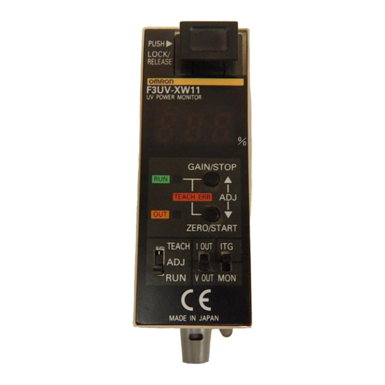
- Page 8 F3UV F3UV J MONITORS WITH FIBER OPTICS F3UV-XW11/-XW41 Measurement/Teaching indicator Illuminated green: Teaching OK Fiber lock Flashing red: Teaching error Illuminated red: Start light intensity integration Operation indicator Illuminated orange: Judgement out- Digital % display put ON Processing mode switch...
- Page 9 F3UV F3UV J FUNCTIONS Name Function Indicator functions Measurement/teaching indicator · Illuminated green: Teaching OK · Flashing red: Teaching error · Illuminated red: Start light intensity integration Operation indicator · Illuminated orange: Judgement out put ON Digital display · Percentage display when operating in light intensity monitor mode...
-
Page 10: Operation
F3UV F3UV Operation J I/O CIRCUIT CONFIGURATION Monitors with Built-in Amplifiers Monitors with Optical Fibers F3UV-XW11 (NPN Output) Brown 12 to 24 VDC Power Operation Load Load (green) (orange) Black Analog output Internal Shield circuit Controller, White etc. Judgement Gray... - Page 11 F3UV F3UV Dimensions Unit: mm (inch) J MONITORS WITH BUILT-IN AMPLIFIERS Main Units F3UV-A30/-A03 Light receiving window Power/Operation indicators 35.5 Sensitivity adjuster 7.4 dia. (1.40) 4 dia. Mounting Hole Dimensions 16.9 19.4 Two, M3 (0.67) (0.76) 9.5 dia. 20±0.1 (0.79±0.004)
- Page 12 F3UV F3UV Protective Cover (Protects Display.) Installed Protective Cover F39-HU2 36.05 (0.63) (1.42) (0.01) 11.8 0.55 (0.46) (0.02) 12.6 (0.55) (0.50) 17.8 (0.08) (0.70) Material: Stainless steel (SUS304-CSP) 2.5 dia. (0.10) (0.09) 12.2 (0.48) Installed 1/6.5 Filtering Cover Two light receiving windows 1/6.5 Filtering Cover...
- Page 13 F3UV F3UV J MONITORS WITH OPTICAL FIBERS Main Units Amplifier F3UV-XW11/-XW41 Sensitivity setting/threshold value up button Zero-point setting/threshold value up button 7-segment display Monitor/Integral mode switch Fiber lock button Current/Voltage output switch (3.50) (0.83) Measurement/teaching RUN/ADJ/TEACH mode switch indicator (green/red)
- Page 14 F3UV F3UV Lock washer Lock nuts (2) Base Unit 6 dia. Detection surface* M8 ´ 1 15 dia. (0.24) F3UV-HM (0.59) 5 dia. (0.20) 13.2 (0.52) (0.51) 15.2 (0.67) (0.60) (1.54) *Material: Stainless steel (SUS303) Fiber Unit Flexible tube, Note: The max. temperature is 2.8 dia.
- Page 15 Sensor closer to the UV light source, until Monitor. If separate power supplies are used for the F3UV and the operation indicator lights. connected devices, always turn ON the F3UV’s power supply first.
- Page 16 F3UV F3UV J PRECAUTIONS FOR THE J OPERATION AND ADJUSTMENT F3UV-XW11/XW41 1. Install the Amplifier Unit. 2. Connect the Fiber Unit to the Amplifier Unit. Installation 1. Installation Torque 3. Turn ON the power supply. 4. Select an operating mode with the operation mode switch.
- Page 17 F3UV F3UV J FIBER UNIT/BASE UNIT 4. Fiber Insertion Location When inserting the Fiber Unit into the Amplifier Unit, Installation always insert the Fiber Unit completely as shown in the following diagram. Installing the Head Unit When connecting the Head Unit and Fiber Unit, tighten to a torque of 0.78 N-m (0.57 ft lbs) max.
- Page 18 F3UV F3UV J APPLICATION EXAMPLES...
-
Page 19: Reference Information
F3UV F3UV Reference Information J WIRE GAUGE J CONVERSIONS Diameter Diameter Length (mm) (in) 1 inch = 25.4 mm 1mm = 0.03937 inch 0.099 0.361 0.014 Torque 0.129 0.405 0.016 1 kgf S m = 86.796 lbf S in 1 in S lb = 0.01152 kgf S m 0.163... - Page 20 F3UV F3UV Sketch NOTE: DIMENSIONS SHOWN ARE IN MILLIMETERS. To convert millimeters to inches divide by 25.4. OMRON ELECTRONICS, INC. OMRON CANADA, INC. One East Commerce Drive 885 Milner Avenue Schaumburg, IL 60173 Scarborough, Ontario M1B 5V8 1-800-55-OMRON 416-286-6465 Cat. No. E315--E3--1 10/00 Specifications subject to change without notice.
Need help?
Do you have a question about the F3UV and is the answer not in the manual?
Questions and answers