Advertisement
Quick Links
Download this manual
See also:
Instruction Manual
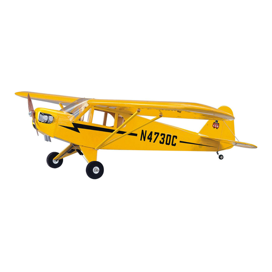
No.867
PIPER J-3
Cub
GP/EP
SPECIFICATIONS
WING SPAN :1720mm
LENGTH:1095mm
2
WING AREA:42dm
WEIGHT:2300-2600g
RADIO:4 CHANNELS
ENGINE: .46(2C) .56(4C)
Warning
An RC aircraft is not a toy! If misused, it can cause serious bodily
MTH
HOBBY PRODUCTS INDUSTRIAL CO., LTD.
harm and damage to property. Fly only in open areas, following all
www.mth.com.tw mthhobby@mth.com.tw
instructions included with your radio.
MTH HOBBY 2014
Before beginning the assembly, remove each part from its bag for
inspection. Closely inspect the fuselage, wing panels, rudder and
stabilizer for damage. If you find any damaged or missing parts,
contact the place of purchase.
Advertisement

Related Manuals for Super Flying Model PIPER J-3 Cub


Summary of Contents for Super Flying Model PIPER J-3 Cub
- Page 1 No.867 PIPER J-3 GP/EP SPECIFICATIONS WING SPAN :1720mm LENGTH:1095mm WING AREA:42dm WEIGHT:2300-2600g RADIO:4 CHANNELS ENGINE: .46(2C) .56(4C) Warning An RC aircraft is not a toy! If misused, it can cause serious bodily HOBBY PRODUCTS INDUSTRIAL CO., LTD. harm and damage to property. Fly only in open areas, following all www.mth.com.tw mthhobby@mth.com.tw instructions included with your radio.
- Page 2 Place the main wing and hinges on Mix 10-min epoxy and spread the working table. generous amount of epoxy on the wing joiner. Fit the wing joiner into the main wing. Apply tape on the conjunction temporary until the epoxy dry enough. Bend the hinges several times.
- Page 3 Place the servo on the servo tray and Place the servo tray on the center of Using z-bend pliers, make a z-bend Find the pre-serving opening on both the main wing set. Use marker to secure it in place with the screws at the marked location on each rod sides of the fuselage for assembling mark the location of the servo tray on...
- Page 4 window set and secure on the pieces of needle to fix the stabilizer 12 mm fuselage. Apply tape on the window on the fuselage. set for holding it in place until the glue is dry enough. 60.2 mm 18.5 Place the black covering, decorative Use epoxy to glue the struts together muffler and spring on the working and use tape to secure the struts...
- Page 5 Spread generous super glue on the Spread some epoxy on half of the Use a sharp hobby knife to open a V There is a gap between vertical and hinges and insert the hinges into the dowel and insert into the main wing. slot (depth: 2mm) on the marked horizontal on both sides.
- Page 6 fuselage. Use needle or tape to hold Hole of the wood dowel. Slide a piece the hardware bag and place on the the vertical in place until it's of heat shrink tubing over each end working table. completely dry. of the wood dowel and shrink it in place using a heat gun.
- Page 7 motor. The length of the motor 205mm x 2 pieces for installing on assembly can be adjusted by the top of horizontal. increasing or decreasing the wooden 180mm x 2 pieces for installing on spacers. the bottom of horizontal. Insert the end of the wire into the conjunction of eyelet.
- Page 8 Remove the canopy. Use 2mm driller Find the pre-served gear slot on the Use sharp hobby knife to remove the to drill hole on the marked position. bottom of fuselage. Use hobby knife planking on the cooling hole. to remove the covering on the slot. Insert one piece of hook-and-loop strap through the battery tray.
- Page 9 secure the cowling in palce. Use hobby to remove the covering Spread epoxy to secure the plastic Use 2x5mm tapping screws to over the vent. engine on two sides of cowling. (It's secure the hinges on the struts. Sprinting black on the decorative only one side for GP version.) plastic engine.
- Page 10 FOR GP VERSION with engine mounting brackets, M4x30mm screws and nuts. Connect with throttle rod. Secure the muffler. Install the fuel tube from the fuel tank pickup line to the carburetor fuel nipple. The vent line will be installed onto the pressure nipple after the muffler is installed.
- Page 11 80~90mm 15mm 15mm The C.G. Point is 80~90mm back from the leading edge against the fuselage. 15mm 15mm 35mm 35mm...
Need help?
Do you have a question about the PIPER J-3 Cub and is the answer not in the manual?
Questions and answers