Advertisement
Quick Links
MTH
HOBBY PRODUCTS INDUSTRIAL CO., LTD.
www.mth.com.tw mthhobby@mth.com.tw
MTH HOBBY 2015
No.EP-46K
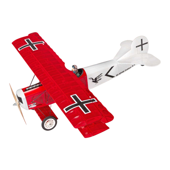
FOKKER D.VII
SPECIFICATION:
Wing span: 1200mm
Motor: 800~900 KV brushless
Wing area: 41 dm
Thrust: 1.4 KGS and up
Length: 990mm
Battery: Li-Po 4-cell 2200mAh and up
Weight: 1400g, including battery
ESC: 50A
Radio: 4 channels
Warning
An RC aircraft is not a toy! If misused, it can cause serious bodily
harm and damage to property. Fly only in open areas, following all
instructions included with your radio.
Before beginning the assembly, remove each part from its bag for
inspection. Closely inspect the fuselage, wing panels, rudder and
stabilizer for damage. If you find any damaged or missing parts,
contact the place of purchase.
1:7.4
Advertisement

Related Manuals for Super Flying Model EP-46K


Summary of Contents for Super Flying Model EP-46K
- Page 1 No.EP-46K FOKKER D.VII 1:7.4 SPECIFICATION: Wing span: 1200mm Motor: 800~900 KV brushless Wing area: 41 dm Thrust: 1.4 KGS and up Length: 990mm Battery: Li-Po 4-cell 2200mAh and up Weight: 1400g, including battery ESC: 50A Radio: 4 channels Warning An RC aircraft is not a toy! If misused, it can cause serious bodily harm and damage to property.
- Page 2 No ce Please pay a en on to the following 3 steps, make sure all the planking and direc on is correct before gluing. 1. Please refer to page 2. Please refer to page 19 3. Please refer to page 20: &...
- Page 3 TOP MAIN WING ASSEMBLY Recommendation: Try to find a flat surface planking (L:1200 mm; w:400mm) or glass as working table for the following steps. Try to find the 2 pieces of W11 and one piece of W12 from the laser-cutting parts bag and place them on the working table.
- Page 4 instant glue to secure the joint places on place. Fit the rib W6 from the center part. Fit other ribs W7, W8, W8, W7, W9, W10, the leading edge. W12, W13, W14 in order. Press the W16R and makes the ribs fit into Use A piece of double-side adhesive tape the slots.
- Page 5 BOTTOM MAIN WING ASSEMBLY Try to fit the W20 on the main wing (near Place W23, W24, W25, W26, W27 as the Place MW7 (2 pieces), MW8 (2 pieces) the leading edge); and fit the W21 on the picture indicated on the working table. and MW9 (2 pieces) on the working table Place the MW3 and MW2 on the working main wing near the rear edge.
- Page 6 relatives slots. Don't apply any glue to the ribs. Top view of both MW9 combinations. Place MW10 (4 pieces) and MW11 (2 Top view of the left and right MW11 pieces) on the working table. combinations. Try to fit the 5mm dowel MW1 as the leading edge.
- Page 7 the rear edge. LANDING GEAR SUB WING ASSEMBLY Please check if there is any joint places Place the following parts on the working need to be secured by instant glue. Apply table in order: Place the DW7 (4 pieces) and Dw8 Make sure the alignment of ribs on the W5;...
-
Page 8: Elevator Assembly
Make sure the alignment of every ribs and Place DW1 on the working table. Completion of the sub wing and wit for Use sanding paper (#150-200) to trim both every angle must be 90 degree; use apply films. sides of horizontal. Don't trim too much; instant glue to secure the joint places. - Page 9 Place H2, H3, H6 and H7 on the working Use sandingpaper to trim the surface. Please refer to the drawing on next step Close view of the V shape on the tip. It is table for assembling elevator. also workable to use sanding paper to trim Don't trim too much.
- Page 10 Try to fit the H6 into V1 and use instant Close view of the round edge. Use wooden planning tool to trim the Use sanding paper to trim the surface of glue to secure the H6 in place. leading edge of the V3 into V shape (30 the rudder.
- Page 11 FUSELAGEASSEMBLY Use hobby knife to cut the hole on the Use hobby knife to cut a V slot from the Try to place the F21 on F20 and the rudder for inserting hinges.The location drilling holefor installing tail gear. second F20 on F22. Please note the holes Place F6 and F7 on the working table.
- Page 12 F17A F17A Hammer M3 Tee nut into F27. Drop some Place F6, F8, F9, F16 on the working Close view of the small recess marking on Place F1R, F1L, F2R, F2L, F15, F3 instant glue around the nut. table. Please note there is a small recess the F6 and F16.
- Page 13 Place F16, F1R and F1L combinations on Try to fit the F1L onto the F16. Make sure Place the F10, F11, F12, F13, F14, F19 Use instant glue to secure the contacting the working table. the angle between two combinations is and F28 on the working table as the places.
- Page 14 Try to fit the F19 onto the fuselage and Try to fit the head of F17 into the slot on Fit the F18 into the slot on F10. Use sanding paper to trim the excess part drop some instant glue to secure it in F5 (the front board on the fuselage).
- Page 15 Use UHU glue to secure F23 inside the F6 Try to fit the F27 inside the fuselage with Use UHU glue to secure the F26 on the Use sanding paper to trim the edges of the (firewall) for reinforcement. the Tee nut face upward. Use instant glue center part of the gear mount.
-
Page 16: Canopy Assembly
Close view of the round edges (R3). After applying the covering on the top and The rudder rod tubing will go through the Use F33 as the triangle ruler and try to fit sides of the fuselage; insert the rod tubing right hole on the F9.Iron on the covering the F31 on the center part of F29. - Page 17 Spray the red color onto the white canopy. Remove the masking tape and the paper. Make sure the alignment of the edges and Try to find 2 pieces of preserving markings Wait for it dried enough. Place the canopy and main construction place some heavy thing on top of it.
- Page 18 Place the machine gun decal, F38 plastic Use instant glue to secure the F36 (with Place the F37 and vacuum formed engine Apply the decorative sticker on the slot facing back) on the canopy closed to on the working table. vacuum formed engine.
- Page 19 Apply the decorative sticker on both sides Color the muzzle and trigger into black. Color the pilot as the flyer like. Completion of the canopy. of butt. Place the machine guns inside the slots Colored pilot for reference. (It is available 2 pieces of MW17 are for the strut.
- Page 20 F38 F39 F40 F1R F2R F1L F2L F17A MW17 MW16...
- Page 21 W16 L W16 R MW15 MW15 MW10 MW10 MW13 MW13 MW11 MW11 MW10 MW10 MW12 MW12 MW14 MW14 DW5 DW5...
- Page 22 Place the ruler on the conjunction of the Insert the hinges as the picture shown. Drop some instant glue to secure the Drop some instant glue to secure the main wing and aileron. Use hobby knife to Spread UHU glue on the surface of hinges hinges into the elevator.
- Page 23 Try to find the pre-serving holes on the Use soldering to melt out the covering Try to find the pre-serving 8 holes for both Use soldering to melt out the covering main wing for servo, for cable exit, for over the screw holes. sides of fuselage.
- Page 24 There are two pre-serving holes on the top Use soldering to melt out the covering Try to find the hole on the side of rudder Use ironer to trim the edges of the slots. of sub wing. Please refer to the picture. over the slots.
- Page 25 Place the bottom main wing on the Place the DW9 gauge on the center Use ironer to trim the edges of the slots. Insert the axles into the slots on the sides working table. Try to find 2 pre-serving position of the sub wing. Use rubber band of sub wing.
- Page 26 on the center slot. Remove the vertical. Use hobby knife to Remove the tail wing. Use hobby knife to Place the fuselage, vertical and horizontal remove the covering inside the marking remove the covering inside the marking on the working table. Please refer to the Try to find 2 pre-serving slots on the area carefully.
- Page 27 ¤ ¤¦ «¦ ¤ P13. on the fuselage. Use hobby knife to cut out the 0.35mm Drop some instant glue to secure the Keep the distance between the end of the Place the servos, rod connectors, plastic hole for installing rudder hinge on the rudder hinges into the vertical and tubing and the end of rod around 15mm;...
- Page 28 operation of the ESC and motor before securing the propeller. Therefore, please don't secure the propeller right now. Place the ESC, propeller, aluminum nut, Use hobby knife to cut off the center circle Try to fit the venting net onto the FRP motor and its relative accessories on the hole on the fire wall.
- Page 29 Use sanding paper to trim the ends of Use the wing strut gauge as the guide and The longer metal end will be connected Top view of installing struts to the screws. Use wing strut gauge (including in insert the black plastic ball-end to both with strut.
- Page 30 Install the z-bend into the outmost hole of the servo arm. Adjust the aileron toque rod length by screwing in or out until the aileron is exactly in the neutral position when the servo is centered and the clevis is in the aileron horn. Place a piece of silicon tube over the clevis for avoiding accidentally coming open.
- Page 31 The cable and plug outside the fuselage can be put into the exit holes on the fuselage and the top wing for neat looking. (When disassemble the main wing set: 1) Get the plug out the exit hole on the top wing.
- Page 32 Place the machine gun decal, 4mm plastic Apply the decorative sticker on both sides Apply the decorative sticker on the barrel. Place the pilot inside the pilot seat. Use tube, balsa barrel, and F40 butt on the of butt. 2.6x8mm tapping screws and 3x10mm working table.
- Page 33 25mm 25mm SF-EP46 Fokker D.VII 25mm 25mm 40mm 40mm 77mm FOR THE EP VERSION CG point is 77mm from the leading edge of the top main wing.
Need help?
Do you have a question about the EP-46K and is the answer not in the manual?
Questions and answers