Table of Contents
Advertisement
Quick Links
Instruction Manual Book
ITEM CODE:BH116.
SPECIFICATION
1
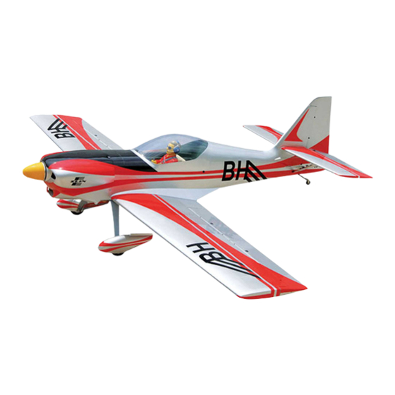
Wingspan: 1,700 mm
66.93 inches.
1 Length
: 1,300 mm
51.18 inches.
1 Weight
: 3.4 kg
7.48 lbs.
1 Radio
: 04 channels.
1 Servo
: 05 servos.
1 Glow Engine: 55
2 stroke; 72
4 stroke.
Parts listing required (not included).
1 Electric Motor: O.S.(OMA-5020-490).
1 Battery: 5-6 Cells-Li-Poly-18.5-22.2V-5.500mAh.
1 Speed control: 80A.
1 Propeller: 14 x 8.
Made in Vietnam.
Advertisement
Table of Contents

Subscribe to Our Youtube Channel
Related Manuals for Black Horse Model ZLIN 50LS


Summary of Contents for Black Horse Model ZLIN 50LS
- Page 1 Instruction Manual Book ITEM CODE:BH116. SPECIFICATION Wingspan: 1,700 mm 66.93 inches. 1 Length : 1,300 mm 51.18 inches. 1 Weight : 3.4 kg 7.48 lbs. 1 Radio : 04 channels. 1 Servo : 05 servos. 1 Glow Engine: 55 2 stroke; 72 4 stroke.
- Page 2 Instruction Manual Item code: BH116 This instruction manual is designed to help you build a great flying aeroplane. Please read this manual thoroughly before starting assembly of your ZLIN 50LS. Use the parts listing below to identify all parts. WARNING.
-
Page 3: Safety Precaution
ZLIN 50LS - Instruction Manual Item code: BH116 Caution: this model is not a toy! If you are a beginner to this type of powered model, please ask an experienced model flyer for help and support. If you attempt to operate the model without knowing what you are doing you could easily injure yourself or somebody else. -
Page 4: Installing The Aileron Servo
ZLIN 50LS - Instruction Manual Item code: BH116 REPLACEMENT SMALL PARTS 3x 20mm. 5x 40mm. 4x 30mm. 3x12mm 3x 15mm. 1. Wheel pants. 2. Aluminium landing gear. 3. Wheels. 4. Plastic- Engine mount. Bottom side 5. Fuel Tank. 6. Spinner. - Page 5 ZLIN 50LS - Instruction Manual Item code: BH116 Temporary pin to keep hinge centered. Repeat the procedure for the other wing Assemble then apply drops of thin C/A to center of hinge,on both sides. half. INSTALLING THE AILERON CONTROL HORN Install aileron control horn as same as picture below.
-
Page 6: Installing The Aileron Linkages
ZLIN 50LS - Instruction Manual Item code: BH116 Bend Aileron Control cut after. horn. Repeat the procedure for the other wing 4. Locate one nylon servo arm, and using half. wire cutters,remove all but one of the arms. Using a 2mm drill bit, enlarge the third hole... - Page 7 ZLIN 50LS - Instruction Manual Item code: BH116 Drill a hole 4mm diameter. Aluminium tube. 220 mm Bottom side Aileron servo Aileron Repeat the procedure for the other wing half. THERE ARE TWO OPTIONS: 1. ELECTRIC MOTOR 2. ENGINE MOUNT.
- Page 8 ZLIN 50LS - Instruction Manual Item code: BH116 Secure. Rotor sharft. Motor. Front view. Battery tray.
-
Page 9: Installing The Engine Mount
ZLIN 50LS - Instruction Manual Item code: BH116 2. OPTION 2: ENGINE MOUNT. COWLING. INSTALLING THE ENGINE MOUNT. 1 1) Slide the cowl over the motor and line See pictures below: up the back edge of the cowl with the marks you made on the fuselage. - Page 10 ZLIN 50LS - Instruction Manual Item code: BH116 Secure Mark point Drill a hole 2mm diameter. Mark point 3 x 20mm Mark point Secure.
-
Page 11: Installing The Throttle Cable
ZLIN 50LS - Instruction Manual Item code: BH116 INSTALLING THE THROTTLE CABLE. Connector. 1. Install one adjustable metal connector through the third hole out from the center of one servo arm, enlarge the hole in the servo arm using a 2mm drill bit to accommodate the servo connector. - Page 12 ZLIN 50LS - Instruction Manual Item code: BH116 FUEL TANK. INSTALLING THE STOPPER ASSEMBLY 1. The stopper has been pre-assembled at the factory. Silicon tube. (Silicon tube not included) Secure. Fuel pick- up tube Vent tube Fuel fill tube 2. Using a modeling knife, cut one length of...
- Page 13 ZLIN 50LS - Instruction Manual Item code: BH116 1 2. While keeping the back edge of the cowl flush with the marks, align the front of the cowl with the crankshaft of the engine. The Tie wrap. front of the cowl should be positioned so the crankshaft is in nearly the middle of the cowl opening.
-
Page 14: Installing The Spinner
ZLIN 50LS - Instruction Manual Item code: BH116 Secure Machine screw. Secure. Front view. INSTALLING THE SPINNER. Install the spinner backplate, propeller and spinner cone. The spinner cone is held in place using two 3mm x 12mm wood screws. 3x15mm... -
Page 15: Installing The Elevator Servo
ZLIN 50LS - Instruction Manual Item code: BH116 INSTALLING THE ELEVATOR SERVO. Temporary pin to keep hinge centered. Elevator servo 1. Install the rubber grommets and brass collets into the elevator servo. Test fit the Assemble then apply drops of thin C/A to center of hinge,on both sides. - Page 16 ZLIN 50LS - Instruction Manual Item code: BH116 Epoxy glue. C/A glue. Bottom side. ELEVATOR CONTROL HORN AND ELEVATOR PUSHROD INSTALLATION. Elevator control horn install as same as the Epoxy glue. way of aileron control horn. Please see pic- tures below.
-
Page 17: Elevator Pushrod Installation
ZLIN 50LS - Instruction Manual Item code: BH116 Elevator pushrod Bottom side. Elevator pushrod Elevator pushrod E l e v a t o r cotrol horn ELEVATOR PUSHROD INSTALLATION. Elevator pushrod install as same as the way of aileron pushrod. -
Page 18: Horizontal Stabilizer Struts
ZLIN 50LS - Instruction Manual Item code: BH116 Secure Secure. HORIZONTAL STABILIZER STRUTS. Plastic parts of elevator 3 x 15mm. pushrod. Secure 3x15mm Cut. Secure. -
Page 19: Rudder Installation
ZLIN 50LS - Instruction Manual Item code: BH116 Installing CA Hinges for the Rudder C/A glue Cut the covering away from the slot. Bottom side. Temporary pin to keep hinge centered. RUDDER INSTALLATION. Assemble then apply drops of thin Rudder servo install as same as method of C/A to center of hinge,on both sides. -
Page 20: Rudder Control Horn Installa- Tion
ZLIN 50LS - Instruction Manual Item code: BH116 RUDDER PUSHROD INSTALLATION. RUDDER CONTROL HORN INSTALLA- TION. Rudder pushrod install as same as the way of aileron pushrod. Rudder control horn install as same as the way of aileron control horn. Please see pic- M2 lock nut. -
Page 21: Mounting The Tail Wheel Bracket
ZLIN 50LS - Instruction Manual Item code: BH116 1 2. Mark the locations of the two mounting screws. Remove the tail wheel bracket and drill 2mm pilot holes at the locations marked. Bottom side C/A glue MOUNTING THE TAIL WHEEL BRACKET. - Page 22 ZLIN 50LS - Instruction Manual Item code: BH116 Bottom side. Remove covering MAIN GEAR INSTALATION. PARTS REQUIRED 1 1) Assemble and mounting the wheel pants as shown in the following pictures. 5x40mm Mark point. Mark line. Secure.
-
Page 23: Installing The Switch
ZLIN 50LS - Instruction Manual Item code: BH116 4 x 20mm. Switch Secure. INSTALLING THE RECEIVER AND BATTERY. 1 1. Plug the servo leads and the switch lead into the receiver. You may want to plug an aileron extension into the receiver to make plugging in the aileron servo lead easier when you are installing the wing . -
Page 24: Wing Attachment
ZLIN 50LS - Instruction Manual Item code: BH116 See picture wing attach to fuselage. Wing bolt. Installing the fuselage hatch as same as picture below. WING ATTACHMENT. 1Locate the aluminium wing dihedral brace. 25 mm 520 mm *** Test fit the aluminium tube dihedral brace into each wing haft. -
Page 25: Control Throws
1 4. Check the control surface. 1 5. Check the receiver antenna . It should be fully extended and not coiled up inside the fuselage. 1 6. Properly balance the propeller. We wish you many safe and enjoy- able flights with your ZLIN 50LS.
Need help?
Do you have a question about the ZLIN 50LS and is the answer not in the manual?
Questions and answers