
Related Manuals for Hendi 4xGN2/3


Summary of Contents for Hendi 4xGN2/3
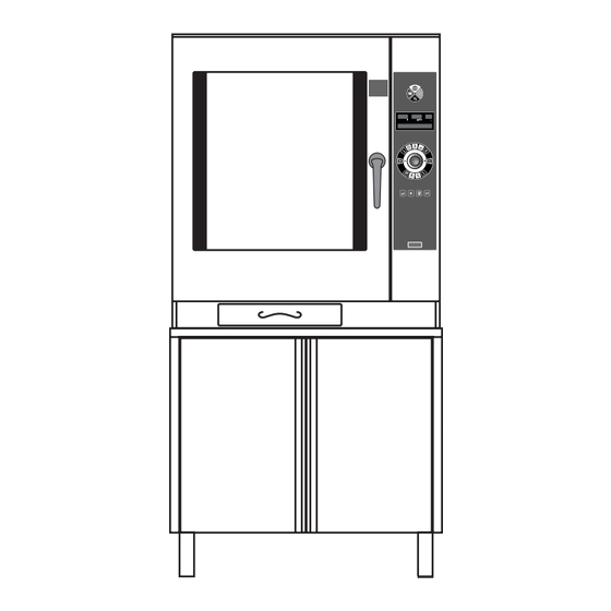
- Page 1 INSTALLATION AND MAINTENANCE MANUAL COMBINATION OVEN WITH AND WITHOUT STEAM GENERATOR Technical service 90023730rev01...
-
Page 3: Table Of Contents
CONTENTS Page 1 • GENERAL REMINDERS 2 • TECHNICAL DATA 3 • SPECIAL REQUIREMENTS FOR THE INSTALLATION SITE 4 • STATUTORY REQUIREMENTS, TECHNICAL REGULATIONS AND DIRECTIVES 5 • POSITIONING 6 • ELECTRICAL CONNECTIONS AND EQUIPOTENTIAL BONDING 7 • POINTS TO REMEMBER WHEN MAKING THE ELECTRICAL CONNECTION 8 •... -
Page 4: General Reminders
1 •GENERAL REMINDERS • The oven must be installed, commissioned • Example of a data plate: and maintained only by a Lainox authorized service agent. • Carefully read the directions given in this TYP. ME 061 P 2003 manual; they contain important information on xxxxxxxxxx safety during installation, operation and 400 V... -
Page 5: Technical Data
2 • TECHNICAL DATA TABLE 1: GENERAL DATA - ELECTRIC OVENS Oil-proof Supply Total power Chamber Boiler connecting Model Frequency Amps Motor voltage input power power cable 3N AC 400 V 5 x 1 mm 50 Hz 3.25 kW 3.15 kW 1 x 0.20 Kw 4 x GN 2/3 3 AC 230 V... - Page 6 2 • TECHNICAL DATA TABLE 3: GENERAL WATER DATA WITH STEAM GENERATOR WITHOUT STEAM GENERATOR Softened water Softened water Water Water Water Water Model consumption Model consumption pressure kPa connection pressure kPa connection max.l/h max.l/h 6 x GN 1/1 4 x GN 2/3 200 - 500 2 x R 3/4"...
-
Page 7: Special Requirements For The Installation Site
3 • SPECIAL REQUIREMENTS FOR THE INSTALLATION SITE • The room where the oven is to be fitted has • The room must have a water drain in a to be well ventilated with all the openings good position for the oven to be installed, required for rooms with gas installations its specifications are given under the (see specific regulations). -
Page 8: Statutory Requirements, Technical Regulations And Directives
4 • STATUTORY REQUIREMENTS, TECHNICAL REGULATIONS AND DIRECTIVES Throughout installation it is vital to observe the following requirements: • any health and hygiene standards • the regulations of the electrical power applicable to kitchens and eating places; supply company or agency; •... - Page 9 5 • POSITIONING • Remove all packing materials and peel away the protective plastic film from all external surfaces of the oven. • For free-standing models, the appliance needs to be levelled: small differences in level of the supporting surface can be eliminated with the adjustable feet (by screwing or unscrewing them).
-
Page 10: Electrical Connections And Equipotential Bonding
6 • ELECTRICAL CONNECTIONS AND EQUIPOTENTIAL BONDING • As this oven is a type X appliance (oven • The oven must be kept in an equipotential without power cable and plug), the cable and system. This connection is made by wiring a other hardware needed to make the conductor of nominal cross section 10 mm connection to the electrical power supply must... -
Page 11: Water And Drain Connections
8 • WATER AND DRAIN CONNECTIONS 8.1 • WATER PRESSURE supplying water that is too softened or too The pressure of the water in the network aggressive, and scaling in the oven and in must be between 200 and 500 kPa, as the water system in the case of supplying already stated under the heading water that is too hard. - Page 12 8 • WATER AND DRAIN CONNECTIONS 8.5 • DRAINING The water is drained off by gravity through a heat-resistant pipe DN 50 (not flexible), maximum length 2 m, installed at an angle of no less than 4°. Mean temperature of the drain water: 65 °C.
-
Page 13: Vents
9 • VENTS • Under no circumstances must vents A and B be shut, blocked or ducted into other pipes. A - Vent to extract vapours from the oven B - Safety vent 10 • GAS CONNECTION PROCEDURES 10.1 • GAS CONNECTION 10.3 •... - Page 14 10 • GAS CONNECTION PROCEDURES Stack connection Installation type B13 pipe Extraction with natural draught fitted with a damper Adaptor and a heat-resistant pipe (see "Flue gas temperatures" in Table 4 under the heading Damper “Technical Data”) connected to the stack. Never under any circumstances must flue gases be ducted away directly utilizing a mechanical extraction system.
-
Page 15: Operating At The Rated Heat Output
11 • OPERATING AT THE RATED HEAT OUTPUT 11.1 • All appliances, during final testing in the 11.4 • The lower calorific value of the gas can be factory, are fitted for the type of gas shown on checked with the supply company or agency, the sticker next to the data plate. - Page 16 11 • OPERATING AT THE RATED HEAT OUTPUT CHECKING NOMINAL HEAT CAPACITY Check the combustion, CO (ppm) and CO Check the depth of the screw "A" in values, with an appropriate instrument: accordance with table 5 of the “Tecnical gas Start the oven working, 180 °C convection data”...
-
Page 17: Commissioning And Testing
12 •COMMISSIONING AND TESTING 12.1 • Check the appliance and the entire 12.4 • Carefully refit the right-hand side that was installation straight after connecting. removed for the above work. Check in particular: • there are no traces of the protective film on 12.5 •... -
Page 18: Important Information For The User
13 • IMPORTANT INFORMATION FOR THE USER 13.1 • With the user manual to hand, show the 13.5 • Explain to the user that certain faults in user the functions, safety devices, operation are often due to simple errors or appropriate use and, above all, the time oversights such as failure to switch on or intervals... -
Page 19: Installation Diagrams
14 • INSTALLATION DIAGRAMS DISTANCES TO OBSERVE We recommend keeping a distance of 500 mm on the right-hand side in order to carry out maintenance work. DO NOT INSTALL APPLIANCES WITH A SOURCE OF HEAT ON THE RIGHT-HAND SIDE OF THE OVEN CAUTION: if the ambient temperature to the right of the... - Page 20 NOTES 90023730rev01...
- Page 21 NOTES 90023730rev01...
- Page 22 NOTES 90023730rev01...
Need help?
Do you have a question about the 4xGN2/3 and is the answer not in the manual?
Questions and answers