Tait TB7100 Installation And Operation Manual
Hide thumbs
Also See for TB7100:
- Service manual (370 pages) ,
- Operation manual (40 pages) ,
- Installation manual (28 pages)

Related Manuals for Tait TB7100


Summary of Contents for Tait TB7100
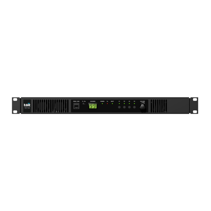
- Page 1 TB7100 base station Installation and Operation Manual MBB-00001-02 Issue 2 December 2005...
-
Page 2: Issue
Website: http://www.taitworld.com To our European customers: Tait Electronics Limited is an environmentally responsible company which supports waste minimization and material recovery. The European Union’s Waste Electrical and Electronic Equipment Directive requires that this product be disposed of separately from the general waste stream when its service life is over. -
Page 3: Table Of Contents
3.4.6 Transmitter Audio Processing....... 38 TB7100 Installation and Operation Manual... - Page 4 5.4 Replacing the Transmitter Module ........57 TB7100 Installation and Operation Manual...
- Page 5 7.5.9 Verification ......... . . 100 TB7100 Installation and Operation Manual...
- Page 6 7.8.1 Connecting to the PC ........105 7.8.2 TB7100 Programming Application ......105 7.8.3 Mandatory Settings .
-
Page 7: Preface
Copyright All information contained in this manual is the property of Tait Electronics Limited. All rights are reserved. This manual may not, in whole or in part, be copied, photocopied, reproduced, translated, stored, or reduced to any electronic medium or machine-readable form, without prior written permission from Tait Electronics Limited. -
Page 8: Document Conventions
The characters xx represent the issue number of the documentation. All available documentation is provided on the CD (406-00047-xx) supplied with the base station. Updates may also be published on the Tait support website. Technical notes are published from time to time to describe applications for Tait products, to provide technical details not included in manuals, and to offer solutions for any problems that arise. -
Page 9: Publication Record
Publication Record Issue Publication Date Description May 2005 First release December 2005 Internal AC power supply, A4 and D1 bands added. TB7100 Installation and Operation Manual © Tait Electronics Limited December 2005... - Page 10 TB7100 Installation and Operation Manual © Tait Electronics Limited December 2005...
-
Page 11: Introduction
Configuration without provision for internal AC power supply* *cover removed The TB7100 is a software and hardware link-configured base station which is designed for operation in a large variety of standard frequency ranges. It makes extensive use of digital and DSP technology. Many operating parameters such as channel spacing, audio bandwidth and signalling are controlled by software. -
Page 12: Frequency Bands
The 25W base station is available in the following frequency bands: The 50W/40W base station is available in the following frequency bands: B1 (50W) H5 (40W) H7 (40W) Introduction TB7100 Installation and Operation Manual © Tait Electronics Limited December 2005... -
Page 13: Power Supply Options
DC backup power option. In case of AC mains failure the base station will automatically and seamlessly switch to DC power input. If no internal AC power supply is fitted, an external Tait T809-10-87xx power supply can be used to supply the DC voltage required. -
Page 14: Product Codes
Product Codes This section describes the product codes used to identify products of the TB7100 base station product line. The product codes of the TB7100 base station product line has the format: TBBaabb-cde-ff where: aa identifies the frequency band of the receiver:... -
Page 15: Mechanical Description
If the internal AC power supply unit is fitted, the base station includes an additional fan and an AC filter module The modules and components are interconnected by looms and cables. TB7100 Installation and Operation Manual Mechanical Description © Tait Electronics Limited December 2005... -
Page 16: Tray
UI cables (not shown). The UI board also has a speaker connector A volume knob is fitted to the shaft of the volume-control potentiometer. Figure 2.2 UI board Cables not shown. Mechanical Description TB7100 Installation and Operation Manual © Tait Electronics Limited December 2005... -
Page 17: Receiver Module
DC power connector and the 50W/40W version has a black DC power connector. For more information on the connectors, refer to “Connections” on page Figure 2.3 Receiver module TB7100 Installation and Operation Manual Mechanical Description © Tait Electronics Limited December 2005... -
Page 18: Transmitter Module
An L-shaped gap pad and (with the 50W/40W version) a rectangular gap are fitted between the board and the heatsink to improve heat transfer. Figure 2.4 Transmitter module Mechanical Description TB7100 Installation and Operation Manual © Tait Electronics Limited December 2005... -
Page 19: Si Board
(to fan power board on fan duct) temperature control connector (to temperature sensor on transmitter heatsink). For more information on the connectors, refer to “Connections” on page Figure 2.5 SI board TB7100 Installation and Operation Manual Mechanical Description © Tait Electronics Limited December 2005... -
Page 20: Ac Power Supply Unit
. In case of a mains failure, this signal will cause the power circuitry on the SI board to switch to DC external input. Figure 2.6 AC power supply unit, filter module and fan Mechanical Description TB7100 Installation and Operation Manual © Tait Electronics Limited December 2005... -
Page 21: Functional Description
Module Internal power Transmitter/SI Receiver Internal power Module Power Supply Unit 115V/230V Receiver/SI Selector Switch Fan Power Board Internal power UI Board UI/Receiver UI/Transmitter Speaker Prog/Mic Connector TB7100 Installation and Operation Manual Functional Description © Tait Electronics Limited December 2005... - Page 22 The audio signal is routed through the UI board to the speaker for monitoring purposes. The SI board provides power to the transmitter and receiver modules. Power and Ground The receiver modules provides power to the UI board. Functional Description TB7100 Installation and Operation Manual © Tait Electronics Limited December 2005...
-
Page 23: Receiver Operation
The output of the first IF (intermediate frequency) stage is then down-converted using an image- reject mixer to a low IF of 64kHz. TB7100 Installation and Operation Manual Functional Description © Tait Electronics Limited December 2005... -
Page 24: Digital Baseband Processing
AGC (value of present gain). With these two inputs and a calibration factor, the RF signal strength at the antenna can be accurately calculated. Functional Description TB7100 Installation and Operation Manual © Tait Electronics Limited December 2005... -
Page 25: Audio Processing And Signalling
UI board via a buffer amplifier. The output configuration of the audio power amplifier is balanced and drives an internal speaker. The power delivered to the speaker is limited by its impedance. The speaker has 16Ω impedance. TB7100 Installation and Operation Manual Functional Description © Tait Electronics Limited December 2005... -
Page 26: Transmitter Operation
The amplified microphone signal is converted to a digital stream by a 16-bit ADC with integral anti-alias filtering (0.1 to 3.2kHz). The digital stream is transported to the DSP for further audio processing. Functional Description TB7100 Installation and Operation Manual © Tait Electronics Limited December 2005... -
Page 27: Frequency Synthesizer
The FCL provides the reference frequency for the RF PLL. It generates a high-stability reference frequency that can be both modulated and offset in fine resolution steps. TB7100 Installation and Operation Manual Functional Description © Tait Electronics Limited December 2005... - Page 28 VCO in the RF PLL, combining to produce a flat modulation response down to DC. Reference modulation is usually applied directly to the TCXO. Functional Description TB7100 Installation and Operation Manual © Tait Electronics Limited December 2005...
- Page 29 FCL nominal frequency; the TCXO frequency itself is not adjusted. The items KVCO and KVCXO are the control sensitivities of the RF VCO (in MHz/V) and VCXO (in kHz/V) respectively. The latter has temperature compensation. TB7100 Installation and Operation Manual Functional Description © Tait Electronics Limited December 2005...
-
Page 30: Rf Power Amplifier
The timing between these two stages is critical to achieving the correct overall wave shape in order to meet the specification for transient ACP (adjacent channel power). A typical ramping waveform is shown in Figure 3.4. Functional Description TB7100 Installation and Operation Manual © Tait Electronics Limited December 2005... - Page 31 For a given power level the look-up table values are scaled by a steady-state power constant so that the ramp waveform shape remains the same for all power levels. TB7100 Installation and Operation Manual Functional Description © Tait Electronics Limited December 2005...
-
Page 32: User Interface Operation
AD6521 CODEC voltage reference TCXO frequency receiver front end transmitter driver and final gate bias limit transmitter power control deviation and squelch. Functional Description TB7100 Installation and Operation Manual © Tait Electronics Limited December 2005... - Page 33 LCD. The keys are scanned and the LCD and LED indicators updated approximately every 50ms. The switch controls what is displayed on the LCD and also whether the transmitter module or the receiver module will be programmed. TB7100 Installation and Operation Manual Functional Description © Tait Electronics Limited December 2005...
- Page 34 Transmitter SPI Shift Registers Rx SPI Data Tx/Rx Switch +13V8 Rx Prog Data Transmitter Electronic Module Switching Prog/Mic Connector Mic Audio Fan Power Connector Fan Power Board Functional Description TB7100 Installation and Operation Manual © Tait Electronics Limited December 2005...
-
Page 35: System Interface Operation
(RSSI) receiver gate output receiver inhibit input 13.8VDC (1.5A) output tone on idle (TOI). These functional parts are described in detail below. TB7100 Installation and Operation Manual Functional Description © Tait Electronics Limited December 2005... - Page 36 RX DIG IO RX GATE AUX IO RX GATE RSSI Receiver RSSI Module Serial Data RX DATA Connector 13.8V 3.3V Temperature Sensor Fan Control Fan Power Board Functional Description TB7100 Installation and Operation Manual © Tait Electronics Limited December 2005...
-
Page 37: Internal Power Distribution
DC input. The DC power input of the base station is protected by a rear panel fuse. The 13.8V is distributed directly to TB7100 Installation and Operation Manual Functional Description © Tait Electronics Limited December 2005... -
Page 38: Serial Data
3.3V, 4.5V, 9V, 13.8V 3.4.2 Serial Data Tait High Speed Data (THSD) is a proprietary protocol of Tait Electronics THSD Limited that can be used with the base station. This allows the base station configured in either data repeater or data modem modes to pass data speeds up to 12kbps on a narrow-band channel and 19.2kbps on a wide-band... -
Page 39: Opto Isolated Keying
SYSTEM receiver gate signal. This may be used in linking applications to prevent unwanted receiver audio signals from appearing at the SI board output connector. TB7100 Installation and Operation Manual Functional Description © Tait Electronics Limited December 2005... -
Page 40: Fan Operation
Dissipation of Heat from Internal AC unit to keep them cool. Some air is passed through a small heatsink to keep Power Supply Unit the current-carrying semiconductor devices cool. Functional Description TB7100 Installation and Operation Manual © Tait Electronics Limited December 2005... -
Page 41: Installation
Ensure that all power sources (AC and DC) are disconnected before opening the base station. TB7100 Installation and Operation Manual Installation © Tait Electronics Limited December 2005... -
Page 42: Explosive Environments
You can obtain further information on antistatic precautions and the dangers of electrostatic discharge (ESD) from standards such as ANSI/ESD S20.20-1999 or BS EN 100015-4 1994. Installation TB7100 Installation and Operation Manual © Tait Electronics Limited December 2005... -
Page 43: Antenna Load
Regulatory Information 4.3.1 Distress Frequencies The 406 to 406.1MHz frequency range is reserved worldwide for use by Distress Beacons. Do not program transmitters to operate in this frequency range. TB7100 Installation and Operation Manual Installation © Tait Electronics Limited December 2005... -
Page 44: Fcc Compliance
4.3.3 Unauthorised Modifications Any modifications you make to this equipment which are not authorised by Tait Electronics Ltd. may invalidate your compliance authority’s approval to operate the equipment. 4.3.4 Health, Safety and Electromagnetic Compatibility in Europe... -
Page 45: Environmental Conditions
Because it is outside the scope of this manual to provide comprehensive information on this subject, we recommend that you conform to your country's standards organisation or regulatory body. TB7100 Installation and Operation Manual Installation © Tait Electronics Limited December 2005... -
Page 46: Recommended Tools
Pozidriv PZ1 screwdriver for the M3 pan head self-tapping screws used to secure the fans. You can also obtain the TBA0ST2 tool kit from your nearest Tait dealer or Customer Service Organisation. It contains the basic tools needed to install, tune and service the base station. - Page 47 BUSY VOLUME BUSY VOLUME BUSY VOLUME BUSY VOLUME BUSY VOLUME ≥10cm (≥4in) BUSY VOLUME BUSY VOLUME BUSY VOLUME BUSY VOLUME ventilation slots airflow entry blanking panels airflow exit TB7100 Installation and Operation Manual Installation © Tait Electronics Limited December 2005...
- Page 48 /h (11cfm) per base station in the cabinet. If you have any other configuration, the performance of your system will depend on how closely you comply with the base station airflow requirements described above. Installation TB7100 Installation and Operation Manual © Tait Electronics Limited December 2005...
-
Page 49: Installing The Base Station
AC connector on the left-hand side of the rear panel (refer Figure 6.2 on page ground point on the right-hand side of the rear panel rather than on the left-hand side different SI board and internal cables. TB7100 Installation and Operation Manual Installation © Tait Electronics Limited December 2005... -
Page 50: Power Supply Options
DC backup power option. In case of AC mains failure the base station will automatically and seamlessly switch to DC power input. If no internal AC power supply unit is fitted, an external Tait T809-10-87xx power supply can be used to supply the DC voltage required. -
Page 51: Mounting The Base Station
(front panel mounted down) or side to side. For transport or in installations subject to vibration, the base station should be supported at the rear using a transit bracket (Tait recommends to use the TB7100 transit bracket, Tait part number 302-05282-00). Figure 4.4... -
Page 52: Cabling
TBBA03-01 wall mounting kit TBBA03-02 duplexer kit (mechanical configuration without internal AC power supply unit) TBBA03-03 duplexer kit (mechanical configuration with internal AC power supply unit) TMAA02-01 fist microphone. Installation TB7100 Installation and Operation Manual © Tait Electronics Limited December 2005... -
Page 53: Replacing Modules
In this case, you will have to restore the configuration from a back-up file. Refer to the section “Preparation for Operation” on page 77 for more information. TB7100 Installation and Operation Manual Replacing Modules © Tait Electronics Limited December 2005... -
Page 54: Removing The Base Station And Opening The Tray
Use a PZ2 Pozidriv screwdriver to remove the four M6 screws, and remove the base station from the rack. Use a Torx T10 screwdriver to remove the 15 countersunk screws. Remove the tray cover Replacing Modules TB7100 Installation and Operation Manual © Tait Electronics Limited December 2005... -
Page 55: Replacing The Ui Board
Use a Torx T10 screwdriver to fasten the three screws to 4.5lb·in (0.5N·m). Plug the speaker connector into the UI board. Fit the volume knob onto the shaft and press firmly until fully seated. TB7100 Installation and Operation Manual Replacing Modules © Tait Electronics Limited December 2005... -
Page 56: Replacing The Receiver Module
Use a Torx T10 torque-driver to tighten the screws 4.5lbf·in (0.5N·m). Connect the cables to the RF , DC power , system interface and user interface connectors. Replacing Modules TB7100 Installation and Operation Manual © Tait Electronics Limited December 2005... -
Page 57: Replacing The Transmitter Module
Use a Torx T10 torque-driver to fasten the temperature sensor with the screw to 4.5lbf·in (0.5N·m). Connect the cables to the RF , DC power , system interface and the user interface connectors. TB7100 Installation and Operation Manual Replacing Modules © Tait Electronics Limited December 2005... -
Page 58: Replacing The Si Board
(PZ1) on the heatsink of U406 to 4.5lb·in (0.5N·m). Connect the system interface cables to the transmitter and the receiver, the fan control cable , the temperature sensor cable , and the DC power cables Replacing Modules TB7100 Installation and Operation Manual © Tait Electronics Limited December 2005... -
Page 59: Replacing The Transmitter And Receiver Fans
Slide the fan duct into the chassis. Plug the fan control loom into the fan power board Use a Torx T10 screwdriver to fasten the four screws to 4.5lb·in (0.5N·m). TB7100 Installation and Operation Manual Replacing Modules © Tait Electronics Limited December 2005... -
Page 60: Replacing The Fan Power Board
Use a Torx T10 screwdriver to remove the screw (Figure 5.4, attaching the temperature sensor board to the transmitter module. Fitting is carried out in reverse order. Replacing Modules TB7100 Installation and Operation Manual © Tait Electronics Limited December 2005... -
Page 61: Replacing The Ac Power Supply Unit, Fan And Filter Module
Slide the AC filter module from its position and remove it. Figure 5.7 Replacing the AC power supply unit, fan, filter module, and speaker Cables not shown. Torx T10 4.5lb·in 4.5lb·in Torx T10 4.5lb·in TB7100 Installation and Operation Manual Replacing Modules © Tait Electronics Limited December 2005... -
Page 62: Replacing The Speaker
Use a Torx T10 screw driver to remove the two screws and washers securing the speaker to the tray. Fitting is carried out in reverse order. The torque for the Torx T10 screws is 4.5lb·in (0.5N·m). Replacing Modules TB7100 Installation and Operation Manual © Tait Electronics Limited December 2005... -
Page 63: Final Reassembly
4.5lb·in (0.5N·m). Fit the fuse at the rear of the base station. Figure 5.8 Final reassembly (configuration with internal AC power supply unit) Fuse TB7100 Installation and Operation Manual Replacing Modules © Tait Electronics Limited December 2005... - Page 64 Figure 5.9 Final reassembly (configuration without internal AC power supply unit) Fuse Replacing Modules TB7100 Installation and Operation Manual © Tait Electronics Limited December 2005...
-
Page 65: Connections
Configuration with internal AC power supply unit shown Connector For information on the factory connector and the internal options connector of the transmitter and receiver, refer to the PCB information. TB7100 Installation and Operation Manual Connections © Tait Electronics Limited December 2005... -
Page 66: External Connectors
Ensure that all power sources (AC and DC) are disconnected before opening the base station. Connections TB7100 Installation and Operation Manual © Tait Electronics Limited December 2005... - Page 67 Recommended DC power connection Circuit Breaker or Fuse TB7100 base station Battery The ground point is a terminal for grounding the tray to the mounting rack. Ground Point TB7100 Installation and Operation Manual Connections © Tait Electronics Limited December 2005...
- Page 68 The RF connector is an N-type connector with an impedance of 50Ω. Important The maximum RF input level is +27dBm. Higher levels may damage the radio. Signal Name Signal Type Notes RF analog RF ground rear view Connections TB7100 Installation and Operation Manual © Tait Electronics Limited December 2005...
- Page 69 ≥1.7 V, low ≤0.7 V Digital output/Tx relay output active low, sinks up to 250mA Rx audio output output <4.4V 13.8 volt output power output resetable SMD fuse 1.5A TB7100 Installation and Operation Manual Connections © Tait Electronics Limited December 2005...
- Page 70 1 2 3 4 5 6 7 8 input transmit data input MIC_AUD_IN input voice band (microphone) input ground external view output receive data not connected not connected Connections TB7100 Installation and Operation Manual © Tait Electronics Limited December 2005...
-
Page 71: Internal Connectors
DC power connectors for the 50W/40W and 25W versions. Signal name Signal type Notes AGND ground 50W/40W SPK– analog output not connected SPK+ analog output not connected external view 13.8VDC DC power input external view TB7100 Installation and Operation Manual Connections © Tait Electronics Limited December 2005... - Page 72 1 closest to PCB CH SPI D1 input input CH SPI CLK output output SPK- no connection output speaker audio SPK+ no connection output speaker audio Connections TB7100 Installation and Operation Manual © Tait Electronics Limited December 2005...
-
Page 73: Si Board Connectors
TX_AUX_GPI2 input digital input TX_AUD_TAP_OUT no connection TX_RSSI no connection TX_MIC_AUD output external view TX_AUD_TAP_IN output Tx audio TX_GND ground ground TX_13V8 no connection no connection TB7100 Installation and Operation Manual Connections © Tait Electronics Limited December 2005... - Page 74 RX_AUX_GPI2 input digital input RX_AUD_TAP_OUT input receive audio RX_RSSI input RSSI RX_MIC_AUD no connection external view RX_AUD_TAP_IN no connection RX_GND ground ground RX_13V8 no connection no connection Connections TB7100 Installation and Operation Manual © Tait Electronics Limited December 2005...
-
Page 75: Ui Board Connectors
RX_CH_SPI_D0 input RX_CH_LE input RX_CH_GPIO1 input digital ground RX_+3V3 input +3V3DC for PCB external view RX_CH_SPI_DI output RX_CH_SPI_CLK input RX_CH_SPK- input speaker audio RX_CH_SPK+ input speaker audio TB7100 Installation and Operation Manual Connections © Tait Electronics Limited December 2005... - Page 76 Connections TB7100 Installation and Operation Manual © Tait Electronics Limited December 2005...
-
Page 77: Preparation For Operation
TB7100 Installation and Operation Manual Preparation for Operation © Tait Electronics Limited December 2005... -
Page 78: Line-Controlled Base
TBA0STU calibration test unit (CTU) which includes the CTU adaptor and CTU cable, or TBA0ST1 calibration test unit (CTU), TBB0STU-TBB CTU adaptor (220-02068-xx) and CTU cable (219-02888-xx) PC, programming cables and the TB7100 programming application digital voltmeter DC power supply (not necessary with internal AC power supply unit option) -
Page 79: Test Equipment Setup
(CTU) used for TB8000 and TB9000 base station equipment, so only some of the features on the CTU apply to the TB7100 base station. The CTU adaptor is plugged into the system connector of the CTU. The CTU cable is plugged into the system connector of the base station. -
Page 80: Link Settings
Fan Control 1 Fan controlled by J207 Default position is 1-2 Fan always on J207 Fan Control 2 Fan Tx key-controlled Default position is 2-3 Fan temperature-controlled Preparation for Operation TB7100 Installation and Operation Manual © Tait Electronics Limited December 2005... -
Page 81: Applying Power
Turn on the power supply and check that the base station powers up correctly: The power LED on the user interface lights up. The LCD indicates the current channel number. TB7100 Installation and Operation Manual Preparation for Operation © Tait Electronics Limited December 2005... -
Page 82: Programming
Open the specifications form and select the correct RF band, not required if the receiver file was read. Open the channels form and add as many channels as are required. For each channel enter: Preparation for Operation TB7100 Installation and Operation Manual © Tait Electronics Limited December 2005... -
Page 83: Receiver Audio Level Adjustment
Verify that the receiver gate opens and the busy LED turns on. Adjust RV503 (BAL OUT) on the rear panel to set the balanced output to the required level (typically -10dBm). TB7100 Installation and Operation Manual Preparation for Operation © Tait Electronics Limited December 2005... -
Page 84: Receiver Functional Testing
Connect the required audio output from the CTU to the audio input port on the test set. Set up the test set to measure the SINAD level. Preparation for Operation TB7100 Installation and Operation Manual © Tait Electronics Limited December 2005... -
Page 85: Transmitter Audio Level Adjustment
Set up the test set audio output to be 1kHz at the required line level (typically –10dBm). Activate the Tx Key switch and verify that the transmission is at the programmed power and frequency. TB7100 Installation and Operation Manual Preparation for Operation © Tait Electronics Limited December 2005... -
Page 86: Transmitter Functional Testing
Activate the Tx Key switch and verify that the measured deviation is 60% of full system deviation. The measured distortion level should be within the transmitter specifications as detailed in the specifications manual. Preparation for Operation TB7100 Installation and Operation Manual © Tait Electronics Limited December 2005... - Page 87 The maximum measured deviation level should not exceed the full system deviation programmed for the channel. Note If the measured value exceeds the programmed settings, the trans- mitter module is either faulty or needs recalibrating. TB7100 Installation and Operation Manual Preparation for Operation © Tait Electronics Limited December 2005...
-
Page 88: Talk Through Repeater
7.4.1 Test Equipment Required The following test equipment is used to setup the base station for talk through repeater operation: PC, programming cables and the TB7100 programming application digital voltmeter DC power supply RF test set with: RF power meter... -
Page 89: Test Equipment Setup
Fan Control 1 Fan controlled by J207 Default position is 1-2 Fan always on J207 Fan Control 2 Fan Tx key-controlled Default position is 2-3 Fan temperature-controlled TB7100 Installation and Operation Manual Preparation for Operation © Tait Electronics Limited December 2005... -
Page 90: Applying Power
“Programming” on page 82 for details. Note If a soft tail setting is required see later in this chapter “Soft Off (Tx Tail Time)” on page 118. Preparation for Operation TB7100 Installation and Operation Manual © Tait Electronics Limited December 2005... -
Page 91: Audio Level Adjustment
The transmitted signal will be the same as received. If subaudible signalling has been enabled, the required sub-tone will also be transmitted. Ensure the deviation is at the desired level. TB7100 Installation and Operation Manual Preparation for Operation © Tait Electronics Limited December 2005... -
Page 92: Alternate Talk Through Repeater Configuration
RV500 (BAL IN) and RV503 (BAL OUT) on the rear panel. The pre/de emphasis links J500 and J501 can be used to set the audio frequency response. Preparation for Operation TB7100 Installation and Operation Manual © Tait Electronics Limited December 2005... -
Page 93: Rf Modem
TBA0STU calibration test unit (CTU) which includes the CTU adaptor and CTU cable, or TBA0ST1 calibration test unit (CTU), TBB0STU-TBB CTU adaptor (220-02068-xx) and CTU cable (219-02888-xx) PC, programming cables and the TB7100 programming application digital voltmeter DC power supply RF test set with:... -
Page 94: Test Equipment Setup
(CTU) used for TB8000 and TB9000 base station equipment, so only some of the features on the CTU apply to the TB7100 base station. The CTU adaptor is plugged into the system connector of the CTU. The CTU cable is plugged into the system connector of the base station. -
Page 95: Applying Power
Turn on the power supply and check that the base station powers up correctly: The power LED on the user interface lights up. The LCD indicates the current channel number. TB7100 Installation and Operation Manual Preparation for Operation © Tait Electronics Limited December 2005... -
Page 96: Programming
Set Power Up State to FFSK transparent mode. Open the data form and in the serial communications tab: In the serial communications setup field set the FFSK transparent Preparation for Operation TB7100 Installation and Operation Manual © Tait Electronics Limited December 2005... - Page 97 In the command mode section disable all check boxes. In the transparent mode section select transparent mode enabled and de-select the other check boxes. Set Power Up State to FFSK transparent mode. TB7100 Installation and Operation Manual Preparation for Operation © Tait Electronics Limited December 2005...
-
Page 98: Programming For Thsd Operation
Open the key settings form and select the required function for each function key. For example: FN1 = Preset Channel FN2 = Preset Channel FN3 = Preset Channel FN4 = None Preparation for Operation TB7100 Installation and Operation Manual © Tait Electronics Limited December 2005... - Page 99 FN1 = Preset Channel (same as transmitter) FN2 = Preset Channel (same as transmitter) FN3 = Preset Channel (same as transmitter) FN4 = Monitor / Squelch override. TB7100 Installation and Operation Manual Preparation for Operation © Tait Electronics Limited December 2005...
-
Page 100: Verification
7.5.9 Verification In order to verify the correct operation as an RF modem a basic functional test can be carried out by sending data between the TB7100 base station and a TM8000 mobile radio. The following equipment will be required:... -
Page 101: Data Repeater
Data Repeater In data repeater mode the base station will transmit all valid received data. Figure 7.8 Data repeater RF In RF Out Receiver Transmitter System Interface TB7100 Installation and Operation Manual Preparation for Operation © Tait Electronics Limited December 2005... -
Page 102: Link Settings
The transmitter will automatically key up when there is data to send. This will not activate the Tx key line and therefore will not activate the fan. Preparation for Operation TB7100 Installation and Operation Manual © Tait Electronics Limited December 2005... -
Page 103: Applying Power
Audio Level Adjustment In this configuration the system interface connector is not used, so it is not necessary to set the line level or line Sensitivity. TB7100 Installation and Operation Manual Preparation for Operation © Tait Electronics Limited December 2005... -
Page 104: Data Repeater Functional Testing
BUSY VOLUME TaitNet Trunking The TB7100 base station can be configured to work with a T1810 or T1711 to form part of a TaitNet MPT1327 Trunking System. For more information, refer to the technical note TN-1033-AN “Using the Tait TB7100 in TaitNet MPT1327 Trunked Networks” available from http://support.taitworld.com. -
Page 105: Programmable Features
The model toolbar, indicates whether the data file is for a receiver or transmitter module. The TB7100 programming application has been optimised for mouse Appearance navigation. Most features can be easily enabled and configured using a check box or drop down list and the frequencies for each channel are simply typed into a table. - Page 106 The reset to defaults feature in the TB7100 programming application makes New Data Files it easy to create a new data file. The required module type (receiver or transmitter) is selected by pressing the appropriate button on the radio model toolbar.
-
Page 107: Mandatory Settings
The mandatory settings in the receiver module are not the same as those in the transmitter module. The reset to defaults feature in the TB7100 programming application will ensure all mandatory settings are correct for the selected module type. -
Page 108: User-Defined Settings
If the system is to be used for data then the data parameters also need to be set correctly: baud rate flow control error correction. Preparation for Operation TB7100 Installation and Operation Manual © Tait Electronics Limited December 2005... - Page 109 Key Action type none User Interface Backlight Mode off, activity, continuous Preferences User Interface Backlight Duration 0…15 Preferences MIC PTT PTT Transmission Type none, voice, data none TB7100 Installation and Operation Manual Preparation for Operation © Tait Electronics Limited December 2005...
- Page 110 Preferences User Interface Backlight Duration 0…15 Preferences MIC PTT PTT Transmission Type none, voice, data Voice External PTT 1 PTT Transmission Type none, voice, data Voice Preparation for Operation TB7100 Installation and Operation Manual © Tait Electronics Limited December 2005...
- Page 111 C-Bypass Out On PTT EPTT1 None A-Bypass In On PTT None C-Bypass Out On PTT EPTT2 None A-Bypass In On PTT None C-Bypass Out On PTT TB7100 Installation and Operation Manual Preparation for Operation © Tait Electronics Limited December 2005...
-
Page 112: Recommended Settings
(voice inversion). The reset to defaults feature in the TB7100 programming application will ensure all recommended settings are in their recommended default state. To explain recommended settings more clearly, two Selcall examples are Recommended Settings Examples given below. -
Page 113: Function Keys
Reset Monitor / Call Cleardown Ignore Two-Tone Silent Operation Keypress Tones Toggle Single In-Band Tone Keypress Tones Volume Squelch Override Low Power Transmit Scanning / Nuisance Delete Monitor TB7100 Installation and Operation Manual Preparation for Operation © Tait Electronics Limited December 2005... - Page 114 Radio Stunned Serial Data Tx In Progress F1 to F4 Key Status Reflect PTT Inhibit Status FFSK Data Received Status Reflect THSD Modem Status CTS Control (DCE) Preparation for Operation TB7100 Installation and Operation Manual © Tait Electronics Limited December 2005...
-
Page 115: Additional Settings
7.10.1 Enabling Subaudible Signalling Read the data file out of the transmitter module. Transmitter Module TB7100 Installation and Operation Manual Preparation for Operation © Tait Electronics Limited December 2005... -
Page 116: Testing Subaudible Signalling
Set up the test set to measure the audio level and distortion. Set the RF signal generator to the correct RF frequency, modulated with a 1kHz audio tone at 60% of full system deviation. Preparation for Operation TB7100 Installation and Operation Manual © Tait Electronics Limited December 2005... -
Page 117: Multiple Subaudible Tones
RTB. A Tx tail (soft off) should be added to overcome this. There is no security for repeaters, as any on-frequency transmission will be repeated, even if it has no subaudible tone. TB7100 Installation and Operation Manual Preparation for Operation © Tait Electronics Limited December 2005... -
Page 118: Soft Off (Tx Tail Time)
The links to enable or disable the tone on idle are shown in the table below. Both links must be in for the TOI to work. Preparation for Operation TB7100 Installation and Operation Manual © Tait Electronics Limited December 2005... -
Page 119: Link Settings
Refer to Figure 7.11 on page 115 for the potentiometer location. Potentiometer Function RV400 Frequency adjust RV401 level adjust TB7100 Installation and Operation Manual Preparation for Operation © Tait Electronics Limited December 2005... -
Page 120: Fan Operation
Fan always on J207 Fan Control 2 Fan Tx key-controlled Default position is 2-3 Fan temperature-controlled Figure 7.12 System interface link positions J221 J500 J503 J400 J502 J501 Preparation for Operation TB7100 Installation and Operation Manual © Tait Electronics Limited December 2005... - Page 121 PTT line does not toggle the TX-key line on the system interface and the THSD is only on for short burst of time never allowing the fan time to spin up. TB7100 Installation and Operation Manual Preparation for Operation © Tait Electronics Limited December 2005...
-
Page 122: Channel Id
Tx digital in/out 1 and Rx digital in/out 1 on the system interface connecter are used then a total of 32 binary or 20 BCD channels are selectable. Requires link W300 to be fitted. Preparation for Operation TB7100 Installation and Operation Manual © Tait Electronics Limited December 2005... -
Page 123: Relay Polarity
This option will allow all 99 channels to be selected from the function buttons. For more information, refer to the technical note TN-1032-AN “Implementing Channel Increment and Decrement on the TB7100” available from http://support.taitworld.com. TB7100 Installation and Operation Manual Preparation for Operation... -
Page 124: Carrier Wave Identification (Cwid)
7.17 Carrier Wave Identification (CWID) CWID is a morse identification feature that can be setup using the TB7100 programming application. 7.17.1 Station ID Can contain a preprogrammed station ID of up to 16 characters in length. The user may wish to prefix the letters DE before the message, meaning “from”. -
Page 125: Transmit Time Out Time
ID repeat time is programmed as 10, the ID or message will be sent every 10 minutes. This will occur during a conversation if one is in progress when the timer goes off. TB7100 Installation and Operation Manual Preparation for Operation © Tait Electronics Limited December 2005... - Page 126 Preparation for Operation TB7100 Installation and Operation Manual © Tait Electronics Limited December 2005...
-
Page 127: Maintenance Guide
The cooling fans have a long service life and have no special maintenance Cooling Fans requirements. If you are using battery, you should check the batteries regularly in Battery accordance with the manufacturer’s recommendations. TB7100 Installation and Operation Manual Maintenance Guide © Tait Electronics Limited December 2005... - Page 128 Maintenance Guide TB7100 Installation and Operation Manual © Tait Electronics Limited December 2005...
-
Page 129: Glossary
Glossary This glossary contains an alphabetical list of terms and abbreviations related to the TB7100 base station. For information about trunking, mobile, or portable terms, consult the glossary provided with the relevant documentation. An accessory is an ancillary device fitted externally to a base station, such as accessory an external microphone. - Page 130 The Calibration Application is a utility for calibrating various parts of the Calibration Application receiver and transmitter circuitry. CCDI2 (computer controlled data interface version 2) is a proprietary Tait CCDI2 command protocol used between computer equipment and a Tait radio. The TB7100 base station does not support CCDI2.
- Page 131 Configuration files have the extension *.t7p. The TB7100 uses two files, one for the receiver and one for the transmitter. When a radio’s squelch threshold is programmed for country squelch, the country squelch radio is more sensitive than if programmed for city squelch and so the radio’s...
- Page 132 European Telecommunications Standards Institute. The non-profit ETSI organisation responsible for producing European telecommunications standards. Glossary TB7100 Installation and Operation Manual © Tait Electronics Limited December 2005...
- Page 133 For example, keypress confidence tones are the tones heard when a keypad key or a function key is pressed and tell the user that an action is permitted. Tait radios use combinations of audible indicators and visual indicators.
- Page 134 A Liquid Crystal Display (LCD) is used on the TB7100 user interface to display channel number. A TB7100 is a line-controlled base station when it receives audio (sending...
- Page 135 No guarantee is given that a feature will work if the recommended settings disable the feature or if a recommended value is changed. TB7100 Installation and Operation Manual Glossary © Tait Electronics Limited December 2005...
- Page 136 The system interface is the set of inputs to and outputs from the base station system interface (excluding RF), provided by a module inside the tray. Glossary TB7100 Installation and Operation Manual © Tait Electronics Limited December 2005...
- Page 137 Temperature compensated crystal oscillator (voltage controlled). The TCXO frequency reference for the RF part of the radio. A TB7100 is a talk through repeater when its audio path is configured to Talk Through Repeater pass the audio it receives on to the transmitter, and its receiver gate signal is configured to key the transmitter.
- Page 138 Settings are specific to the customers application. These are the only settings that need to be changed when configuring a TB7100 for operation. The user interface panel is an area at the front of the base station with user interface buttons, LEDs and other controls that let you interact with the base station.
-
Page 139: Important Notice
MERGED INTO ANOTHER PROGRAM WILL AUTOMATICALLY AND WITHOUT NOTICE FROM CONTINUE TO BE SUBJECT TO THE TERMS AND TAIT IN THE EVENT THAT THE LICENSEE FAILS TO CONDITIONS OF THIS AGREEMENT COMPLY WITH ANY TERM OR CONDITION OF THE LICENSEE MAY NOT DUPLICATE... -
Page 140: Limited Warranty
THAT SUBJECT ONLY TO ANY EXPRESS WRITTEN OR OTHERWISE AT LAW FOR ANY LOSSES OR TERMS OF AGREEMENT TO THE CONTRARY DAMAGES WHETHER GENERAL SPECIAL BETWEEN TAIT AND THE LICENSEE THIS IS THE EXEMPLARY PUNITIVE DIRECT INDIRECT OR COMPLETE AND EXCLUSIVE STATEMENT OF THE... -
Page 141: Directive 1999/5/Ec Declaration Of Conformity
Directive 1999/5/EC Declaration of Conformity Dansk Français Undertegnede Tait Electronics Limited erklærer Par la présente, Tait Electronics Limited déclare herved, at følgende udstyr TBBA4A, TBBB1A que l'appareil TBBA4A, TBBB1A & TBBH5A & TBBH5A overholder de væsentlige krav og est conforme aux exigences essentielles et aux øvrige relevante krav i direktiv 1999/5/EF. - Page 142 TB7100 Installation and Operation Manual © Tait Electronics Limited December 2005...
Need help?
Do you have a question about the TB7100 and is the answer not in the manual?
Questions and answers