Table of Contents
Advertisement
Advertisement
Table of Contents

Related Manuals for Exmark RADIUS


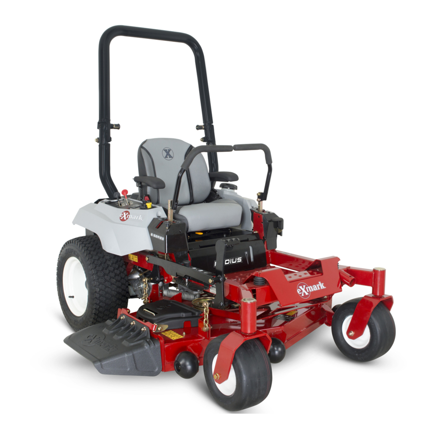
Summary of Contents for Exmark RADIUS
- Page 1 RADIUS ® For Serial Nos. 400,000,000 & Higher Part No. 4502-907 Rev. B...
- Page 2 Canadian standard ICES-002. Ce système d’allumage par ètincelle de vèhicule est conforme à la norme NMB-002 du Canada. For all models that do not have Exmark engines, please refer to the engine manufacturer’s information included with the machine. Labeled power ratings are supplied by the engine...
-
Page 3: Introduction
All Exmark parts are thoroughly tested and inspected before leaving the factory, however, attention is required on your part if you are to obtain the fullest measure of satisfaction and performance. -
Page 4: Table Of Contents
Schematics ............73 Maintenance ............35 Recommended Maintenance Schedule(s) ....35 Periodic Maintenance ........36 Engine Maintenance........36 Servicing the Engine Oil .........40 Servicing the Spark Plug-Exmark 708cc Engine ............48 Servicing the Spark Plug-Kohler Engine ............50 Servicing the Spark Plug-Kawasaki Engine ............51 Check Battery Charge ........52 Check Mower Blades ........53... -
Page 5: Safety
Institute in effect at the time of production. explain this material to them; other languages may be available on our website. Exmark designed and tested this lawn mower to offer • Become familiar with the safe operation of the reasonably safe service; however, failure to comply equipment, operator controls, and safety signs. - Page 6 Safety bones, and other foreign objects which can be DANGER thrown by the machine and may cause personal In certain conditions during fueling, static injury to the operator or bystanders. electricity can be released causing a spark which can ignite gasoline vapors. A fire or DANGER explosion from gasoline can burn you and In certain conditions gasoline is extremely...
- Page 7 Safety Operation damage and make repairs before restarting and operating the mower). WARNING – Before clearing blockages. Operating engine parts, especially the muffler, – Whenever you leave the mower. become extremely hot. Severe burns can occur • Stop engine, wait for all moving parts to stop, and on contact and debris, such as leaves, grass, engage parking brake: brush, etc.
- Page 8 Safety • Be aware that operating on wet grass, across steep DANGER slopes or downhill may cause the mower to lose Operating on wet grass or steep slopes can cause traction. Loss of traction to the drive wheels may sliding and loss of control. Wheels dropping over result in sliding and a loss of braking and steering.
-
Page 9: Maintenance And Storage
Charging or jump starting the battery may • Any accessories, alterations, or attachments added produce explosive gases. Battery gases can to the ROPS must be approved by Exmark. explode causing serious injury. • Keep sparks, flames, or cigarettes away Maintenance and Storage from battery. - Page 10 • Stopping distance increases with the weight of the Unauthorized modifications to the original towed load. Travel slowly and allow extra distance equipment or failure to use original Exmark to stop. parts could lead to serious injury or death. Unauthorized changes to the machine, engine, •...
-
Page 11: Safety And Instructional Decals
Exmark equipment dealer or labels. distributor or from Exmark Mfg. Co. Inc. • Replace all worn, damaged, or missing safety • Safety signs may be affixed by peeling off the signs. - Page 12 Safety 112-9028 1. Warning—stay away from moving parts; keep all guards in place. 109-6014 115-9625 1. Parking 2. Parking brake—engaged brake—disengaged 109-6035 Side Discharge Units Only 116-8283 1. Warning—read the Operator's Manual for instructions on torquing the blade bolt/nut to 55-60 ft-lb (75-81 N-m). 109-6036 1.
- Page 13 Safety 126-4363 1. Cutting/dismemberment hazard, fan and entanglement hazard, belt—Stop engine and remove key before adjusting, servicing or cleaning. 116-8588 1. Read the Operator’s manual. 2. Rotate the drive release knob to loosen, slide the knob, and tighten. 3. Push the machine. 117-2718 126-4784 1.
- Page 14 Safety 126-8161 X-Series Units 1. Read Operator’s manual 3. Press down on latch to unlock seat 4. Rotate seat 2. Slide seat forward 126-6464 Side Discharge Units 1. Thrown objects hazard 3. Cutting/dismemberment - keep bystanders a of hand or foot - stay safe distance from the away from moving parts;...
- Page 15 Safety 131-1097 Exmark 708cc Engine Only 1. Oil drain LH Motion Control 1. Machine speed 4. Neutral 2. Fast 5. Reverse 3. Slow Exmark 708cc Engine Only 1. Shut down engine at full throttle Message Display 1. Hour 4. Neutral 2.
- Page 16 Safety PTO Switch Symbols 1. PTO–disengage 2. PTO–engage Transport Lock 1. Height of cut 2. Pull up to unlock the transport lock 126-6570 1. Throttle-fast 4. Choke-off 2. Throttle-slow 5. Optional light accessory 3. Choke-on...
- Page 17 Safety 126-8151 1. Read the instructions before servicing or performing 4. Refer to the Operator's manual for grease instructions maintenance 2. Time interval 5. Check hydraulic oil level and refer to the Operator's manual or further instructions 3. Check oil level 6.
-
Page 18: Specifications
All units: • Engine Specifications: See your Engine Owner’s – 20 amp charging system fuse Manual (not used on Kohler engines) • Engine Oil Type: Exmark 4–Cycle Premium Engine Oil – 15 amp main fuse • RPM: Safety Interlock System –... -
Page 19: Hydrostatic Ground Drive System
23 x 10.50-12 ◊ Units with 48 or 52 inch decks: Ply Rating Hydro Gear ZT2800 Pressure 13 psi (90 kPa) 13 psi (90 kPa) ◊ Units with 60 inch deck: Hydro Gear ZT3100 • Hydraulic Oil Type: Exmark Premium Hydro Oil. -
Page 20: Cutting Deck
Specifications • Electric clutch: E-Series: – 48 & 52 Inch Decks: 125 ft-lb Mag Stop Drive – 60 Inch Deck: 125 ft-lb Neo-Mag Stop Pneumatic (Air filled) • Deck: Full floating deck is attached to out-front Deck Size 48 & 52 support frame. -
Page 21: Dimensions
Specifications Dimensions Overall Length: Side Discharge Units: Overall Width: 48 inch Deck 52 inch Deck 60 inch Deck X-Series—Side Discharge Units: 81.7 inches 81.7 inches 82.2 inches (207.5 cm) (207.5 cm) (208.8 cm) 48 inch 52 inch 60 inch Deck Deck Deck Rear Discharge Units:... -
Page 22: Curb Weight
Specifications Tread Width: (Center to Center of Wheel Base: (Center of Caster Tire to Tires, Widthwise) Center of Drive Tire) X-Series—Side Discharge Units Side Discharge Units: 48 inch 52 inch 60 inch 48 inch Deck 52 inch Deck 60 inch Deck Deck Deck Deck... -
Page 23: Torque Requirements
Product Overview Torque Requirements Product Overview Bolt Location Torque X-Series: 130-160 ft-lb (176-217 N-m) Blade Drive Sheave Mounting Nut S- and E-Series: 75-85 ft-lb (102-115 N-m) Blade Drive Sheave Mounting Nut Blade Mounting 50-60 ft-lb (68-81 N-m) Bolt (lubricate with anti-seize) Anti-Scalp Roller 50-55 ft-lb (68-75 N-m) -
Page 24: Operation
Operation Operation The choke is used to aid in starting a cold engine. Moving the choke lever forward will put the choke in the “ON” position and moving the choke lever to the Note: Determine the left and right sides of the rear, to the detent, will put the choke in the “OFF”... -
Page 25: Ignition Switch
Operation The unit must be tied down and brake engaged when transporting. Ignition Switch Located on right console (see Figure 6). The ignition switch is used to start and stop the engine. The switch has three positions “OFF”, “ON” and “START”. Insert key into switch and rotate Figure 8 clockwise to the “ON”... -
Page 26: Pre-Start
Operation PTO Engagement Switch the machine has to be pushed by hand, the valves must be in the “released” position (see Figure 9). Located on right console (see Figure 6). Switch must be pulled out (up) to engage the blades. Switch is pushed in to disengage the blades. -
Page 27: Operating Instructions
Operation Do Not add oil to gasoline. Do Not overfill fuel tank. Fill the fuel tank to the bottom of the filler neck. The empty space in the tank allows gasoline to expand. Overfilling may result in fuel leakage or damage to the engine or emission system. -
Page 28: Starting The Engine
Operation attempts. Failure to follow these guidelines can burn out the starter motor. 7. If the choke is in the “ON” position, gradually return choke to the “OFF” position as the engine warms up. Engaging the PTO DANGER The rotating blades under the mower deck are dangerous. -
Page 29: Driving The Machine
Operation 2. Move the motion control levers out to the neutral lock position. 3. Engage the parking brake. 4. Place the throttle midway between the “SLOW” and “FAST” positions. 5. Disengage the PTO. 6. Allow the engine to run for a minimum of 15 seconds, then turn the ignition switch to the “OFF”... -
Page 30: Adjusting The Cutting Height
Operation To turn right, release pressure on the RH motion control lever and the rear of the machine will move towards the rear and to the right. To turn left, release pressure on the LH motion control lever and the rear of the machine will move towards the rear and to the left. - Page 31 Operation See the decal on the top of the deck lift plate for • Side Discharge Units: cut heights. A. Be sure the roller bolts are installed with 5. Push the foot lever forward, pull up on the the spring disc washer between the head transport lock knob and let the deck lower of the bolt and the mounting bracket (see down to the predetermined cut height by slowly...
-
Page 32: Transporting
Operation • Rear Discharge Units: Torque the 3/8 nyloc nut to 30-35 ft-lb (41-47 N-m) (see Figure 19 ). Figure 20 1. Bolt 3. Nut 2. Bumper Figure 19 1. 3/8 inch nyloc-torque to 3. Wheel spacer 7. Move each bumper to the desired position and 50-55 ft-lb (68-75 N-m) secure them with the bolts and nuts. - Page 33 Operation Ensure the ramp is long enough so that the angle with the ground does not exceed 15 degrees (Figure 23). On flat ground, this requires a ramp to be at least four times (4X) as long as the height of the trailer or truck bed to the ground.
- Page 34 Operation g027996 Figure 23 1. Full-width ramp in 4. Ramp is at least four stowed position times (4X) as long as the height of the trailer or truck bed to the ground 2. Side view of full-width 5. H= height of the trailer or ramp in loading position truck bed to the ground 3.
-
Page 35: Maintenance
• Clean the grass and debris build-up from the machine and cutting deck. • Clean the grass build-up from under the cutting deck. • Clean the air cleaner foam element (more often in dusty, dirty conditions)(Exmark 708cc engine). Every 25 hours •... -
Page 36: Periodic Maintenance
Maintenance Maintenance Service Maintenance Procedure Interval • Service the air cleaner paper element (more often in dusty, dirty conditions)(Exmark 708cc engine). • Replace the air cleaner foam element (more often in dusty, dirty conditions)(Exmark 708cc engine). • Replace the air cleaner paper element (more often under extremely dusty, dirty conditions)(Kohler engine). - Page 37 2. Clean around the air cleaner cover to prevent dirt from getting into the engine and causing damage. Servicing the Air Cleaner–Exmark 708cc Engine 3. Lift the cover and rotate the air-cleaner assembly out of the engine (see Figure 25 and Figure 26).
- Page 38 Note: Service the air cleaner more often under extremely dusty, dirty conditions. To learn more about the Exmark twin-cylinder engine go to http://exmark.com/engines or scan the QR 1. Park the machine on a level surface, disengage the code.
- Page 39 Maintenance conditions)(Kawasaki engine). Every 250 hours—Check the safety air filter (more often under extremely dusty, dirty conditions)(Kawasaki engine). Every 500 hours—Replace the safety air filter (more often under extremely dusty, dirty conditions)(Kawasaki engine). Note: Service the air cleaner more often under extremely dusty, dirty conditions.
-
Page 40: Servicing The Engine Oil
Important: Do not attempt to clean the Checking the Engine Oil safety filter. If the safety filter is dirty, then Level–Exmark 708cc Engine the primary filter is damaged. Replace both Service Interval: Before each use or daily filters. - Page 41 5. If the level is low, wipe off the area around the oil fill cap, remove cap/dipstick and add oil to the 4. Check the engine oil level. “FULL” mark on the dipstick. Exmark 4-Cycle Premium Engine Oil is recommended; refer to the following information for an appropriate API rating and viscosity.
- Page 42 “F” 1. Park the machine on a level surface, disengage (FULL) mark on the dipstick. Exmark 4-Cycle the blade control switch, stop the engine, engage Premium Engine Oil is recommended; refer to parking brake, and remove the key.
- Page 43 2. Start the engine and let it run until warm. This fill cap, remove cap/dipstick and add oil to the warms the oil so it drains better. “FULL” mark on the dipstick. Exmark 4-Cycle 3. Disengage the blade control switch and ensure Premium Engine Oil is recommended; refer to the parking brake is engaged.
- Page 44 Maintenance g027799 Figure 37 g029570 Figure 38 5. Change the engine oil filter. Apply a thin film of clean Exmark 4-Cycle Premium Engine Oil to the rubber gasket on the new filter.
- Page 45 6. Slowly pour approximately 80% of the specified Service Interval: After the first 5 hours oil into the filler tube—use oil recommended in Every 100 hours (change the Checking the Engine Oil Level–Exmark it more often under a 708cc Engine section. heavy load or in high temperatures) (Kohler Engine).
- Page 46 Figure 42 5. Change the engine oil filter. Apply a thin film of clean Exmark 4-Cycle Premium Engine Oil to the rubber gasket on the new filter. Note: Ensure the oil filter gasket touches the engine, then an extra 3/4 turn is completed.
- Page 47 Note: Torque the plug to 14 N-m (125 in-lb). Service Interval: After the first 5 hours 5. Change the engine oil filter. Apply a thin film of clean Exmark 4-Cycle Premium Engine Oil to the Every 100 hours (change rubber gasket on the new filter.
-
Page 48: Servicing The Spark Plug-Exmark 708Cc Engine
Note: Ensure the oil filter gasket touches the engine, then an extra 3/4 turn is completed. Servicing the Spark Note: Dispose of the used oil at a recycling Plug-Exmark 708cc Engine center. Service Interval: Every 100 hours/Yearly 6. Slowly pour approximately 80% of the specified (whichever comes oil into the filler tube—use oil recommended... - Page 49 Maintenance Air Gap: 0.030 inch (.76 mm) Removing the Spark Plug-Exmark 708cc engine 1. Disengage the PTO and ensure the parking brake is engaged. g027479 2. Stop the engine, remove the key, and wait for all Figure 48 moving parts to stop before leaving the operating 1.
-
Page 50: Servicing The Spark Plug-Kohler Engine
Maintenance Servicing the Spark Note: If you see light brown or gray on the insulator, the engine is operating properly. A Plug-Kohler Engine black coating on the insulator usually means the air cleaner is dirty. Service Interval: Every 200 hours—Check the spark plug (Kohler Important: Do Not clean the spark plug. -
Page 51: Servicing The Spark Plug-Kawasaki Engine
Maintenance 3. Disconnect the wire from the spark plug. g027478 Figure 53 4. Clean around the spark plug to prevent dirt from falling into the engine and potentially causing damage. 5. Remove the spark plug and metal washer. Figure 52 Checking the Spark Plug–Kawasaki Engine 3. -
Page 52: Check Battery Charge
Maintenance Installing the Spark Plug–Kawasaki Note: To prevent damage due to freezing, battery Engine should be fully charged before putting away for winter storage. 1. Install the spark plug. Make sure that the air gap is set correctly. Check the voltage of the battery with a digital voltmeter. -
Page 53: Check Mower Blades
Maintenance DANGER Jump starting a weak battery that is cracked, frozen, has low electrolyte level, or an open/shorted battery cell, can cause an explosion resulting in serious personal injury. Do Not jump start a weak battery if these conditions exist. 2. - Page 54 4. Blade bolt washer assembly — Torque to 50-60 ft-lb (68-81 N-m) Apply lubricant to threads as needed to Always install the original Exmark blades, prevent seizing. Copper-based anti-seize preferable. Grease acceptable substitute. blade bushings, and blade bolts as shown.
-
Page 55: Check Safety Interlock System
Maintenance Check Safety Interlock System Service Interval: Before each use or daily Important: It is essential that operator safety mechanisms be connected and in proper operating condition prior to use. Note: If machine does not pass any of these tests, Do Not operate. Contact an Authorized Service Dealer. Note: To prevent engine cut-outs on rough terrain, the seat has a 1/2 second time delay before the engine begins to shutdown. - Page 56 Maintenance Check Engine Starting Circuit Chart Note: In the Check Engine Starting Circuit Chart, the state of system item that is bold is being checked in each scenario. System Parking Brake Motion Control Levers Operator Outcome (Blades) Engaged Disengaged Both levers moved in, or either Operator Starter must in seat...
- Page 57 Maintenance Check Shutdown Circuit Chart Note: The state of system item(s) that is bold is being checked in each scenario. System Engine Parking Motion Control Operator Outcome Brake (Blades) Levers Running idle Disengaged Disengaged Both levers moved Raise off Engine must (1/3 throttle) out (neutral lock), of seat (but...
-
Page 58: Check Rollover Protections Systems (Roll Bar) Knobs
Service Interval: Before each use or daily 3. Check expansion tank and if necessary add Check that both the mounting hardware and the Exmark Premium Hydro Oil to the FULL COLD knobs are in good working condition. Make sure the line (see Figure 60). -
Page 59: Lubricate Grease Fittings
6. Pack the bearings with a NLGI grade #1 multi-purpose grease. 7. Insert one bearing, one new seal into the wheel. Note: Seals (Exmark P/N 103-0063) must be replaced. 8. If the axle assembly has had both spacer nuts removed (or broken loose), apply a thread locking adhesive to one spacer nut and thread onto the axle with the wrench flats facing outward. -
Page 60: Replace Emissions Air Intake Filter (If Applicable)
1. Stop engine, wait for all moving parts to stop, and engine. Replace when necessary. remove key or spark plug wire(s). Engage parking Replacement Filters brake Exmark Exmark 2. Squeeze the ends of the hose clamps together and P/N 133-1563 slide them away from the filter. -
Page 61: Change Hydraulic System Filter And Fluid
Important: Before reinstalling new filters, CAUTION apply a thin coat of Exmark Premium Hydro Oil on the surface of the filters rubber seal. Raising the mower deck for service or maintenance relying solely on mechanical Turn the filters clockwise until rubber seal or hydraulic jacks could be dangerous. -
Page 62: Check Spark Arrester (If Equipped)
Maintenance in both forward and reverse directions (5 to • Sheave and clutch retaining bolt in the end of 6 times). Check the oil level, and add oil as engine crankshaft. required after stopping the engine. • Hydro cross member mounting bolts C. -
Page 63: Adjustments
Maintenance Adjustments 8. For 60 Inch Decks Only: A. Raise the deck to the transport (5 inch (12.7 Note: Disengage PTO, shut off engine, wait for cm) cutting height) position. all moving parts to stop, engage parking brake, and remove key before servicing, cleaning, or making any B. -
Page 64: Adjusting The Blade Slope
Maintenance C. Set the gap between the spring and bracket to X-Series—Block Height and Rake Table 3/4–7/8 inch (19–22 mm). Deck Front Block Rear Block Rake “R” Size Height “A” Height “B” Adjusting the Blade Slope 2.63 inches 2.88 inches 1/16–5/16 inch 52, &... -
Page 65: Pump Drive Belt Tension
Maintenance removed (see Figure 66). Save the screw for 1. Drive the machine onto a level surface. reinstallation. 2. Disengage the blade control switch (PTO), move the motion control levers to the neutral locked 10. Measure from the tip of the front blade to the flat position and set the parking brake. -
Page 66: Motion Control Handle Adjustment
Maintenance nut clockwise to shorten and counterclockwise The motion control levers can be adjusted higher or to lengthen. lower for maximum operator comfort. 1. Remove the hardware holding the control lever to the control arm shaft. Figure 71 1. Bolts 3. -
Page 67: Motion Control Linkage Adjustment
Maintenance screw clockwise or counterclockwise to adjust the 2. Raise the rear of machine up and support with travel of the lever. jack stands (or equivalent support) just high enough to allow drive wheels to turn freely. 3. Remove the electrical connection from the seat safety switch, located under the bottom cushion of the seat. -
Page 68: Adjusting The Seat Ride Suspensions-Series Only
Maintenance Figure 74 1. Seat isolator Electric Clutch Adjustment Figure 73 No adjustment necessary. 1. Nut 4. Return to neutral plate 2. Stationary plate 5. Tabs touching return to neutral plate 3. Control plate 8. Shut off unit. Remove jumper wire from wire harness and plug connector into seat switch. -
Page 69: Cleaning
Maintenance Cleaning belt shields, around the fuel tank, around engine and exhaust area, and around hydro fans. Clean Engine and Exhaust Clean Grass Build-Up Under System Area Deck Service Interval: Before each use or daily Service Interval: Before each use or daily (May be required more often in dry or dirty 1. -
Page 70: Battery Disposal
Maintenance Battery Disposal DANGER Battery electrolyte contains sulfuric acid, which is poisonous and can cause severe burns. Swallowing electrolyte can be fatal or if it touches skin can cause severe burns. • Wear safety glasses to shield eyes, and rubber gloves to protect skin and clothing when handling electrolyte. -
Page 71: Troubleshooting
Troubleshooting Troubleshooting Important: It is essential that all operator safety mechanisms be connected and in proper operating condition prior to mower use. When a problem occurs, do not overlook the simple causes. For example: starting problems could be caused by an empty fuel tank. The following table lists some of the common causes of trouble. - Page 72 Troubleshooting Problem Possible Cause Corrective Action Engine loses power 1. Engine load is excessive 1. Reduce the ground speed. 2. Air cleaner is dirty. 2. Clean or replace the air cleaner element. 3. Oil level in the crankcase is low. 3.
-
Page 73: Schematics
Schematics Schematics Electrical Logic Schematic — Exmark Engine... - Page 74 Schematics Electrical Logic Schematic — Kohler Engine...
- Page 75 Schematics Electrical Logic Schematic — Kawasaki Engine...
- Page 76 Exmark Customer Service Department Warranty Conditions The Exmark Warranty Company This warranty applies to Exmark Radius E-Series turf equipment sold in 2101 Ashland Avenue the U.S. or Canada for a period of four years or 500 hours (whichever Beatrice, NE 68310 occurs first).
- Page 77 Exmark Customer Service Department Warranty Conditions The Exmark Warranty Company This warranty applies to Exmark Radius S-Series turf equipment sold in 2101 Ashland Avenue the U.S. or Canada for a period of four years or 750 hours (whichever Beatrice, NE 68310 occurs first).
- Page 78 Exmark Customer Service Department Warranty Conditions The Exmark Warranty Company This warranty applies to Exmark Radius X-Series turf equipment sold in 2101 Ashland Avenue the U.S. or Canada for a period of four years or 1,000 hours (whichever Beatrice, NE 68310 occurs first).
- Page 79 Notes:...
- Page 80 Notes:...
-
Page 81: Service Record
Service Record Date: Description of Work Done: Service Done By:... - Page 83 G011841 Figure 75 This page may be copied for personal use. 1. The maximum slope you can safely operate the machine on is 15 degrees. Use the slope indicator to determine the degree of slope of hills before operating. Do Not operate this machine on a slope greater than 15 degrees. Fold along the appropriate line to match the recommended slope.
- Page 84 Pack) or Fill in Below Engine Model No. and Spec. No. Model No. Engine Serial No. (E/No) Serial No. ©2016 Exmark Mfg. Co., Inc. Part No. 4502-907 Rev. B Industrial Park Box 808 (402) 223-6375 Beatrice, NE 68310 Fax (402) 223-5489...
Need help?
Do you have a question about the RADIUS and is the answer not in the manual?
Questions and answers
What is the correct air pressure for the tires?
The correct tire air pressure for the Exmark RADIUS is around 8 to 9 psi.
This answer is automatically generated
Where do you place jack stands when changing blades
what battery should i replace original with??
what is oil capacity for exmark radius e mower?
The oil capacity for the Exmark Radius E mower is 2.11 quarts.
This answer is automatically generated