Table of Contents
Advertisement
Quick Links
Advertisement
Table of Contents

Related Manuals for Kodak DirectView CR 500 System


Summary of Contents for Kodak DirectView CR 500 System
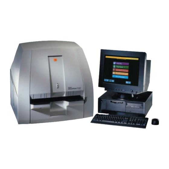
- Page 1 Kodak DirectView CR 500 System H195 0016AC User’s Guide...
- Page 2 Eastman Kodak Company 343 State Street Rochester, NY 14650 © Eastman Kodak Company, 2003 Kodak, DirectView, Ektascan, and MIN-R are trademarks of Eastman Kodak Company. PN 1F1976...
-
Page 3: Table Of Contents
Table of Contents 1 Safety and Related Information Health and Safety Compliance ..........................1-1 Labels ................................1-4 CR 500 System ............................1-7 Safety ..............................1-7 EMC ..............................1-8 Patient Vicinity ............................1-8 CR 500 System (with Isolation Transformer) .....................1-9 Safety ..............................1-9 EMC ..............................1-9 Remote Operations Panel.........................1-11 User Guide Conventions ...........................1-12 Special Messages..........................1-12 2 Overview... - Page 4 Table of Contents 3 Operation and Workflow Starting the System ............................3-1 Logging On...............................3-2 Changing a Password ............................3-3 Shutting Down the System ..........................3-3 Power Failures ..............................3-4 Workflow .................................3-5 Main Menu...............................3-6 Main Menu Functions..........................3-6 Menu Buttons.............................3-6 Navigation Buttons .............................3-7 4 Entering Exam Data Introduction..............................4-1 Entering Patient Information ..........................4-2 New Patient ..............................4-2...
- Page 5 Table of Contents Retrieving Images from DVD/CD Storage ....................5-14 Saving Images to DVD/CD Storage......................5-16 Disc Full Warning ............................ 5-17 Managing Images............................5-18 Managing Failed Delivery Images......................5-19 Managing Unassigned Images ........................5-19 Printing Images ............................. 5-21 Printing Multi-format Images........................5-23 Other Multi-format Settings........................
- Page 6 Table of Contents Cleaning the CRT Screen ..........................8-1 Cleaning the LCD Panel ............................8-2 Removing the Flexible Phosphor Screen......................8-3 Cleaning the Flexible Phosphor Screen......................8-4 Special Cleaning Materials..........................8-4 Replacing the Flexible Phosphor Screen......................8-6 Cassette Cautions..............................8-6 Cleaning Cassettes ............................8-7 Replacing Erase Lamps ............................8-8 9 Key Operator Functions Introduction..............................9-1 Managing Patient Exam Records ........................9-3...
- Page 7 Table of Contents Adding a New Procedure ........................9-27 Locating Procedures.......................... 9-29 Editing Procedures ..........................9-29 Using an Existing Procedure to Create a New Procedure..............9-29 Deleting a Procedure......................... 9-29 HIS/RIS Broker Configuration........................9-30 Introduction ............................9-30 HIS/RIS Broker Configuration......................9-30 Push Configuration ..........................
- Page 8 Table of Contents Configuring a Remote Operator Panel to Multiple CR Systems ............9-58 Configuring Multiple ROPs to Multiple CR Systems ................9-61 Remote Patient Data Entry Software (RPDES)...................9-64 Computer Requirements ........................9-64 Installation Instructions ........................9-64 RPDES Configuration Instructions ......................9-64 RPDES Operation ..........................9-66 Create a RPDES Shortcut on the Desktop....................9-66 Remote Key Operator ..........................9-67 Setting Up the Remote Key Operator....................9-67...
- Page 9 Table of Contents Lietuviðkai..............................10-6 Nederlands ..............................10-6 Norsk ................................10-7 Português ..............................10-7 Suomeksi............................... 10-8 Svenska ................................. 10-8 Overview................................ 10-9 Network Configuration..........................10-9 Start Up ............................... 10-10 Operation ..............................10-10 Using the ROP Touch Screen ........................10-11 Navigation Buttons..........................10-11 Error Messages............................
- Page 10 Table of Contents viii August 1, 2003...
-
Page 11: Safety And Related Information
Company reserves the right to change this information without notice and makes no warranty, express or implied, with respect to this information. Kodak shall not be liable for any loss or damage, including consequential or special damages, resulting from the use of this information, even if loss or damage is caused by Kodak's negligence or other fault. - Page 12 This is a Class I Laser product in conformance with DHHS regulations. This is a Class 1 Laser product in conformance with IEC 60825-1. AUTHORIZED REPRESENTATIVE: Manager, Product Safety, Kodak GmbH; Hedelfingerstr. 54-56, 70327 Stuttgart, GERMANY. This equipment has been tested and found to comply with the limits for a Class A digital device, pursuant to part 15 of the FCC rules.
- Page 13 Safety and Related Information CAUTION The small footprint and specifications of the CR System allow for flexibility in placement of the unit, including in the exam room. When installed in this manner, scatter radiation from the x-ray system may cause image artifacts in two scenarios: •...
-
Page 14: Labels
Safety and Related Information Labels H195_0001DC 1F1976 August 1, 2003... - Page 15 Safety and Related Information H195_0002DC August 1, 2003 1F1976...
- Page 16 Safety and Related Information H195_0003DC 1F1976 August 1, 2003...
-
Page 17: Cr 500 System
H195_0014AC Monitor Kodak DirectView CR 500 System Kodak DirectView CR 500 System (Reader Only) This device is not medical equipment according to EN 60 601-1 and must therefore not enter the Patient Environment as defined in EN 60 601-1-1. The following requirements have to be met: Distance from device to Patient Contact Equipment (see illustration). -
Page 18: Emc
Safety and Related Information CAN/CSA C22.2 No. 60950-00 - Information Technology Equipment, 3rd Edition International / European Union: IEC 60950:1999 / EN 60950: 2000 - Information Technology Equipment IEC 60825-1:2001 / EN 60825-1:2001 - Safety of Laser Products Canada ICES - 003 Issue 3 Class A ITE Emissions U. -
Page 19: Cr 500 System (With Isolation Transformer)
Transformer Mouse Keyboard BAR CODE READER H195_0013AC Monitor Kodak DirectView CR 500 System with Isolation Transformer Safety Canada/International/European Union/USA: IEC 60601-1-1:2000 / EN 60601-1-1:2001 Safety Requirements for Medical Electrical Systems CLASS I EQUIPMENT. INTENDED FOR CONTINUOUS OPERATION. ACCEPTABLE FOR INCIDENTAL OR CASUAL CONTACT WITH THE PATIENT. - Page 20 Safety and Related Information EN 61000-4-4:1995 Electrical Fast Transient/burst immunity EN 61000-4-5:1995 Surge immunity EN 61000-4-6:1996 Immunity to conducted disturbances EN 61000-4-11:1995 Voltage dips, sages, interrupts EN 61000-3-2:1995 Limits for harmonic current emissions EN 61000-3-3:1995 Flicker U. S. A. FCC Emissions, Class A 1-10 1F1976 August 1, 2003...
-
Page 21: Remote Operations Panel
Safety and Related Information Remote Operations U.S.A. Panel UL 1950 Safety for Information Technology Equipment Canada CSA No. 950 60950 Safety for Information Technology Equipment International EN 60950:1992 Safety for Information Technology Equipment (with Amendments A1, A2, A3, and A11) EN 55011:1998 ISM Emissions, Group 1 Class A EN 60601 - 1- 2: 1993 Medical Electrical Equipment Electromagnetic Compatibility... -
Page 22: User Guide Conventions
Safety and Related Information User Guide Conventions Special Messages The following special messages emphasize information or indicate potential risks to personnel or equipment. NOTE: Notes provide additional information, such as expanded explanations, hints, or reminders. Important notes highlight critical policy information that IMPORTANT: affects how you use this guide and this product. -
Page 23: Overview
Overview Product Description The Kodak DirectView CR 500 System is a tabletop Computed Radiology (CR) System. It lets you scan exposed flexible phosphor screens, process the resulting images, and route these images to the appropriate destinations via a 10Base T or 100Base T Ethernet network. The system communicates with DICOM compatible printers, CD/DVD storage, workstations, and archives. - Page 24 Destinations KODAK DIRECTVIEW Archive System Remote Operations Panel KODAK DIRECTVIEW Workstation KODAK DIRECTVIEW Workstation Remote Operations Panel KODAK PACS Link 9410 Acquisition System KODAK DRYVIEW 8100 Laser Imager CR 500 System CR 500 System ETHERNET H195_9000EC 1F1976 August 1, 2003...
-
Page 25: System Components
Options • CD/DVD Writer • External Bar Code Reader • External Modem • Kodak Flexible Phosphor Screens for CR 500 Systems • Kodak DirectView CR 500 Cassettes • Isolation Transformer • Remote Operating Panel • Remote Patient Data Entry Station Personal Computer The computer is an IBM-compatible PC. -
Page 26: Mouse
System with a flat LCD monitor (fixed resolution of 1024 x 768 pixels). CD/DVD Writer You can store and retrieve DICOM Part 10 images by selecting the Kodak Writable CD/DVD R+W System for Kodak DirectView CR Systems as a destination for image delivery, (page 5-8) either as part of the default profile or on an isolated basis. -
Page 27: Cassettes
IMPORTANT: Kodak DirectView CR 500 Cassettes and Kodak Flexible Phosphor Screens for Kodak DirectView CR 500 Systems are sold separately. Make sure the screen size and type matches the label on the cassette, General Purpose (GP) or High Resolution (HR). See the figure on page 4-8. - Page 28 Overview 1F1976 August 1, 2003...
-
Page 29: Operation And Workflow
Operation and Workflow Starting the System To turn on the CR System power: Make sure the power switch on the back of the Reader is ON, or in the I position. Leave the Reader and the computer ON so that they are powered by the UPS. -
Page 30: Logging On
If you are a Technologist and the Tech Login button is present, select Otherwise, enter your configured user name and password. Login Access For more information, see the Security Administrator Functions addendum, Kodak Publication number 1F6710, in this User’s Guide. 1F1976 August 1, 2003... -
Page 31: Changing A Password
Select System Shutdown and select Shutdown/Power Off. Turn off the power to the monitor. NOTE: The UPS shuts down up to one minute after the Kodak DirectView CR 500 Software and Windows 2000 Operating System shut down. NOTE: To remove AC Mains power from the CR 500 System with Isolation Transformer, disconnect the Mains cord from the Isolation Transformer to the AC Mains source. -
Page 32: Power Failures
UPS shuts down the system. CAUTION The UPS battery must be changed by a Kodak authorized Service Provider. The UPS battery contains lead and poses a hazard to the environment and human health if not disposed of properly. -
Page 33: Workflow
Operation and Workflow Workflow Collect patient demographic data. HIS/RIS Broker? Manually enter the Patient Enter Patient Data data on the Scan the Patient ID bar code. Query the Local database. CR System, or Query the HIS/RIS Remote Patient Data database. Entry Station. -
Page 34: Main Menu
Operation and Workflow Main Menu Main Menu Functions The function buttons on the Main Menu are: • Study Data—enter patient data, create new studies, access worklists. • Image Review—view all stored images, reprocess images. • Key Operator Functions—set up and manage system configurations, configure the monitor, access SMPTE Test Pattern (accessed by Key Operator and Applications Consultant only). -
Page 35: Navigation Buttons
Operation and Workflow Name Description Scan Status / Scan Displays scan progress and last image scanned. Cassette Additionally, if some images were not delivered or do not have patient data associated with them, the following buttons may also appear: Failed Delivery Alerts you when the system starts, or any time the Main Menu is displayed, of any image that failed to be delivered to the selected destinations. - Page 36 Operation and Workflow 1F1976 August 1, 2003...
-
Page 37: Entering Exam Data
Entering Exam Data Introduction This section tells you how to enter patient data manually. If you are searching for a patient that has already been submitted in the RIS, see “Entering Patient Information” in this chapter to query for the patient. You can enter Patient and Exam Information at the ROP using the touch screen or at the CR 500 System using drop-down menus accessed by the mouse and the keyboard. -
Page 38: Entering Patient Information
Entering Exam Data Entering Patient Information At the Main Menu, click Study Data. You can now do one of the following: • New Patient—select New Patient and enter information as described below. • Trauma—select Trauma and enter information as described below. •... -
Page 39: Trauma Patient
Entering Exam Data Trauma Patient Select Trauma and proceed to “Entering Exam Information” on page 4-7. The Key Operator can configure some fields to be completed automatically. NOTE: Your Key Operator may have configured a field with a “unique number.” Each time you select a trauma patient, the number increments to identify a new trauma patient. - Page 40 Entering Exam Data Patient Input Screen Select for more patient information, and scroll to select the referring physician. Referring Physician 1F1976 August 1, 2003...
- Page 41 Entering Exam Data Select to select additional image information, such as laterality, and to enter Source to Patient Distance or Source to Image Distance (SID), used in Long-Length Imaging (available on CR 800 /CR 900 and CR 850/CR 950 Systems). Source to Image Distance When a match is found, the Patient Worklist screen appears.
-
Page 42: New Study
Entering Exam Data Patient Worklist Screen New Study Select New Study to create a new study using the patient information from an existing study. 1F1976 August 1, 2003... -
Page 43: Entering Exam Information
Entering Exam Data Entering Exam Information After entering the patient information, enter the exam information into the remaining fields on the Patient Input Screen. There are mandatory and optional fields. You must complete the mandatory fields to submit the record to the CR System. -
Page 44: Mandatory Exam Information
Cassette ID number, the image is unassigned. You must assign the image to a patient. You can change all image and patient data except the Cassette ID. Bar Code Label Non-Tube Side Extremity Label Screen Type Label H195_0015GCA H195_0015GC Kodak DirectView CR 500 Cassette 1F1976 August 1, 2003... -
Page 45: Optional Exam Information
NOTE: After you scan the cassette, the image thumbnail replaces the cassette icon to display the image. 1. Printers such as the Kodak DirectView 8100 Laser Imager or the Kodak DirectView 8700 Laser Imager may print images in the order they were scanned rather than by priority when the CR System is configured to Pass-through Mode. - Page 46 Entering Exam Data 4-10 1F1976 August 1, 2003...
-
Page 47: Scanning, Viewing, And Managing Images
Scanning, Viewing, and Managing Images NOTE: For proper operation and calibration of the 35 x 35 cm cassette, always insert the screen into the cassette so that the black writing is at the cassette door or back edge. It is possible to insert this screen into the cassette in any of four orientations, and if you fail to insert the screen correctly, it could result in both calibration and functional failures:... - Page 48 Scanning, Viewing, and Managing Images – For portrait orientation, place the gray corners at the bottom of the image with the cassette’s gray Tube Side panel facing the X-ray source. IMAGE AREA 7.5 mm TUBE SIDE Cassette ID Label Gray corners 35 x 43 CM Portrait Orientation NOTE: Orienting the cassette properly at exposure eliminates the need to flip...
-
Page 49: Loading Cassettes
Scanning, Viewing, and Managing Images Loading Cassettes WARNING Use only KODAK DIRECTVIEW CR 500 Cassettes. Place the cassette into the cassette feed slot in the CR 500 Reader. CR500 READER NOTE: Be sure that the Tube Side label faces up, and the cassette’s gray corners are towards you. -
Page 50: Viewing Images
Scanning, Viewing, and Managing Images Viewing Images You can configure your system for two viewing modes: • Pass-through Mode • QA Mode Pass-through Mode In Pass-through mode, the completed exam is processed and routed, typically without stopping. When Pass-through mode is configured, a button appears on the Scan Status screen next to the Erase Cassette button. - Page 51 Scanning, Viewing, and Managing Images To accept a single image after viewing, select the thumbnail and select Apply and Accept Image on the Image Viewer screen. Image Viewer If the image is unacceptable, select the thumbnail and select Reject Image. A prompt confirms that you want to delete the selected image.
- Page 52 Scanning, Viewing, and Managing Images Reject Images 1F1976 August 1, 2003...
-
Page 53: Image Review
Scanning, Viewing, and Managing Images If Reject Reason is activated: • Select a Reject Reason. • Enter a Reject comment (optional). • Select Reject Image. If further post-processing is required, see “Guidelines for Optimizing Image Quality” on page 6-1. Image Review You can re-display images that have been accepted and routed for review, modification, and reprocessing. -
Page 54: Working With Images
Scanning, Viewing, and Managing Images Working with Images Reprocessing Images You can modify images before you accept and route them. For information on reprocessing previously delivered images, see page 6-1. You can reprocess the displayed image in several ways, including Edge Enhancement, Contrast, Brightness, etc. - Page 55 Scanning, Viewing, and Managing Images Destinations To select a destination, move the cursor up or down with the arrows. Then select either the + or - to choose the number of copies to send to each. When finished, select Apply, then select Accept Image to route the image. The DVD/CD destination is typically called Local Host.
-
Page 56: Erasing Screens
CR System Main Menu, select Erase Cassette. On the CR 500, insert the cassette. Kodak recommends that you erase all little-used or non-circulating phosphor screen every week or if you suspect it has been exposed to any X-radiation. -
Page 57: Reprocessing Delivered Images
Scanning, Viewing, and Managing Images Reprocessing Delivered Images To reprocess an image: Make a copy of the image to modify. Select the icon of the image you wish to copy. Select Create a Copy of this Image. A copy for you to reprocess appears. The original is unchanged. Select the appropriate button. -
Page 58: Unassigned Images
Scanning, Viewing, and Managing Images Unassigned Images To assign a patient: Select the title bar under the unassigned image. Find the correct name by querying the database or select New Patient and use the keyboard to enter the correct name. Select Assign Image. -
Page 59: Dvd/Cd Storage And Retrieval (Option)
Scanning, Viewing, and Managing Images DVD/CD Storage and Retrieval (option) You can use the Kodak Writable CD/DVD R+W System to store and retrieve images just as you can with any other destination on the system. You can store images to a DVD or CD, and then retrieve them at a later time for reprocessing and redelivery. -
Page 60: Retrieving Images From Dvd/Cd Storage
Scanning, Viewing, and Managing Images Enter a label, such as the date, in the Label window. Select Start Format. Retrieving Images To retrieve images: from DVD/CD Storage At the Main Menu, select Image Review. At the Image Review screen, select Storage. Image Review 5-14 1F1976... - Page 61 Scanning, Viewing, and Managing Images Enter optional search criteria for the Patient Study or Image you are looking for, or enter none to see all studies. Select A list of patient studies and images matching the search criteria appears. • Expand a study, if desired, to show the images included in the study. •...
-
Page 62: Saving Images To Dvd/Cd Storage
Scanning, Viewing, and Managing Images Select the desired study or image to retrieve. Select The system returns to the PEC Input screen, where the image status is updated. An entire study or a single image is retrieved and displayed. Select the desired thumbnail to view, reprocess, and select destinations for delivery as desired. -
Page 63: Disc Full Warning
Scanning, Viewing, and Managing Images Disc Full Warning When the DVD/CD disc in the Writable DVD/CD R+W System reaches approximately 98% full, the following message box appears. Select Continue. This message means that there is room for approximately ten more images on the DVD/CD. -
Page 64: Managing Images
Scanning, Viewing, and Managing Images Managing Images As images are scanned, processed, and routed, the CR System software tracks the images and stores them based on their status. Sometimes an image is not delivered properly or is unassigned. Use the Image Review screen to display images by status for reviewing, reprocessing, or resolving problem images. -
Page 65: Managing Failed Delivery Images
Scanning, Viewing, and Managing Images Image Review Managing Failed When an image is not successfully delivered to one or more of the selected destinations, the text block next to the image is red. The image is stored as a Delivery Images Failed Delivery image. - Page 66 Scanning, Viewing, and Managing Images Select the image you want to assign to the newly created study. Select the Patient Information bar. Search for the patient for whom you created the study and select the new study. Select Assign Image. When the image is assigned, the record turns from orange to green.
-
Page 67: Printing Images
True-size image because the CR image is typi- cally larger than a printer can produce on a comparable film size. a. See Table: CR Image Minification Factors for Common Kodak Printers. WARNING True-size Printing delivers the latent image to the destination at 100%, +/-2%. - Page 68 True-size printing for one-up images so the image printed is the same size as the traditional film. See “Appendix B: Printing Exceptions“ for a list of printing exceptions. CR Image Minification Factors for Common Kodak Printers Film Size Kodak Print-...
-
Page 69: Printing Multi-Format Images
Scanning, Viewing, and Managing Images CR Image Minification Factors for Common Kodak Printers Film Size Kodak Print- Cassette Average Fac- (cm) Size (cm) tor (% of ac- tual scan size) 24 x 30 2180 18 x 24 24 x 30... - Page 70 Scanning, Viewing, and Managing Images Select Select a layout. The available images for the study appear, along with the cassette sizes. NOTE: Depending on the printer type and film size, printing multi-format images may not be possible. 5-24 1F1976 August 1, 2003...
- Page 71 Scanning, Viewing, and Managing Images Colored borders around the thumbnails indicate the image’s multi-format status. • Green — include the image in a multi-format layout, and it has not been included in a previous multi-format layout. • Gray—the image was used in a previous multi-format layout. You can still add the image to the new layout.
- Page 72 Scanning, Viewing, and Managing Images The following table lists common Kodak printers and the CR cassette sizes (images) that can be printed in two-up or four-up format. See “Appendix B: Printing Exceptions“ on page B-1. Kodak Printer Film Size Cassette Size...
- Page 73 Scanning, Viewing, and Managing Images Kodak Printer Film Size Cassette Size Cassette Size Comment Supported on Supported on Two-Up Format Four-Up Format Kodak DryView 8700 Laser 35 x 43 35 x 43 35 x 43 “Appendix B: Imaging System Printing Exceptions“. 35 x 35...
-
Page 74: Other Multi-Format Settings
Scanning, Viewing, and Managing Images Other Multi-format Settings Multi-format Only Check You can compose multi-format prints of images of a variety of statuses: Available, Delivered, Failed, etc. To change the status of an image printed in a multi-format print from Available to Delivered, select the Multi-format Only check box. -
Page 75: Printing Text
Scanning, Viewing, and Managing Images Printing Text There are two text printing options: Internal and External Text Box. The available options depend on how the Key Operator has configured your System. “Configuring a Text Box” on page 9-49. Select the type you want and the location at the Image Processing screen. Printing Internal Text The Text Box content is configured by your Key Operator. -
Page 76: Printing External Text Boxes
Scanning, Viewing, and Managing Images Text Box Select the Print Internal Text Box check box. The text box can be printed in 8 different locations, that is, in each corner either horizontally or vertically. Select the edge of the corner where you want the text box to appear. - Page 77 Scanning, Viewing, and Managing Images Select the Print External Text Box check box. Select the arrow under the check box to select Portrait or Landscape orientation. Print the image. August 1, 2003 1F1976 5-31...
-
Page 78: True-Size Printing (Option)
When you select True-size printing, the image size is the same as the exposed size, similar to traditional processed film. CAUTION For exact measurements, Kodak recommends placing a known marker at the level of the subject when making the exposure and calculating image magnification. -
Page 79: Cm Tick Marks
Scanning, Viewing, and Managing Images Print the image. 1 cm Tick Marks Use the 1 cm Tick Marks option to “burn-in” (Page Glossary-1) markers into the image to help you evaluate image size. The system optionally prints markers 1 cm apart along 2 adjacent sides of either 1-up or multi-format images. - Page 80 Scanning, Viewing, and Managing Images 5-34 1F1976 August 1, 2003...
-
Page 81: Maintaining Image Quality
CR System. Each body part and projection combination produces a unique look for a given image. When using Kodak Flexible Phosphor Screens, the following suggestions will help you obtain optimum image quality: • Apply as much collimation as is practically possible on all images. -
Page 82: Changing Image Orientation
Maintaining Image Quality Changing Image Click the appropriate button to rotate or flip an image. You can rotate through Orientation 360° by rotating in steps of 90° . Tonescale Contrast Brightness Rotate Flip CAUTION Adjusting Contrast Do not change the contrast and brightness unless necessary. and Brightness An image’s contrast and brightness are determined by the window width (contrast) and window level (brightness). -
Page 83: Changing Image Tonescale
Maintaining Image Quality Changing Image If a processed image is not acceptable, you may be able to salvage the image Tonescale by using the raw data. Select Image Tonescale to view the raw data. Adjust the Brightness and Contrast to generate an acceptable image. NOTE: Select Image Tonescale again if you want to return to the Processed Data. -
Page 84: Image Processing
Maintaining Image Quality Image Processing You can alter or reprocess an image at the Image Processing screen. The Image Reprocessing parameters are set up and stored in memory by the Application Consultant or a Key Operator who has attended an advanced image processing class. - Page 85 Maintaining Image Quality Use the following table to make your image processing selections. Parameter Procedure Select the appropriate check box to Black Surround Mask, Black select a function. If you cannot select Bone, Edge Enhancement, it, the option is not available. EVP, 1 cm Scale, and Grid Suppression Select Reprocess Image.
- Page 86 Maintaining Image Quality modify. Function Description Black Surround Mask Blackens the area around the image. Accentuates edges in the image. The default Edge Enhancement edge enhancement values should seldom need to be changed. Changing Edge Enhancement should only be done by someone with a clear understanding and good working knowledge of digital imaging.
-
Page 87: Full Resolution Viewing
Maintaining Image Quality Full Resolution You can pan and zoom the image from the Image Reprocessing screen. Viewing NOTE: This option is not available on the ROP. Image Reprocessing • Select for half-resolution zoom. Half-resolution Zoom August 1, 2003 1F1976... - Page 88 Maintaining Image Quality • Select to view full screen, full-resolution zoom. Only a part of the image is visible at any time. Click and drag to pan other parts of the image. Full Screen View, Full-resolution Zoom Press the keyboard Esc or Enter keys, or touch the spacebar to return to the normal view.
-
Page 89: Improving Image Characteristics
• Change user parameters (a Key Operator function). NOTE: If you cannot correct the problem, in the United States and Canada, contact Kodak Customer Service Center (CSC) for service at 1-800-328-2910, prompt 2, then prompt 3 for further assistance. For other locations, contact your Kodak service center or representative. - Page 90 Maintaining Image Quality Image Problem Recommendations • Confirm an image was captured on the plate. Image is all white or all black • Remove black surround. • Check laser printer for errors; find out if problem is restricted to one or Printed image has stripes for all prints produced on that particular printer.
- Page 91 Maintaining Image Quality Processed Data Histogram This histogram’s position on the LUT shows that an image was captured and processed. NOTE: The Exposure Index is the average code value of the pixels in the active histogram used for processing the image. The image data is the data within the boundary box used for processing the image for the body part.
- Page 92 Maintaining Image Quality 6-12 1F1976 August 1, 2003...
-
Page 93: Troubleshooting
If that doesn't correct the problem, contact your Key Operator. If the Error Message repeats, in the U.S. and Canada, call the Kodak Technical Support Center at 1-800-328-2910. For all other locations, contact your Kodak service center or Kodak representative. -
Page 94: Releasing Cassette And Phosphor Screen Jams
Troubleshooting Releasing Cassette and Phosphor Screen Jams To release a cassette or phosphor screen from the CR 500 Reader, do the following: At the Main Menu select Utility Menu. Select System Recovery. Select Release Cassette. Select Auto Recovery to clear the jam in the system. Remove the cassette and inspect it for the screen. -
Page 95: System Reset
Erase Lamp Plug Thumb screw Advance knob If the problem persists, in the U.S. or Canada, call the Kodak Technical Support Center at 1-800-328-2910. For all other locations, contact your Kodak service center or Kodak representative. NOTE: Before calling Kodak, locate the CR System K Number, located on the Reader’s left panel. -
Page 96: System Status
Troubleshooting System Status The System Status screen provides information on disk and memory utilization, database statistics, and erase lamps. At the Main Menu, select Utility Menu. Select System Status. System Status Clear Pending Images There may be times when you want to clear images that do not go to a destination. - Page 97 Troubleshooting Clear Pending Images August 1, 2003 1F1976...
-
Page 98: Slow System Response (Restart The Browser)
Troubleshooting Slow System Response (Restart the Browser) If you are experiencing slow system response, check your physical memory. “System Status” on page 7-4. If the physical memory utilization is high, restart the browser. At the Main Menu, select Utility Menu. Select System Recovery. -
Page 99: Maintaining Equipment And Cassettes
Maintaining Equipment and Cassettes Cleaning the CR System Surfaces Clean the outer surfaces of the CR System only with water using a soft, lint-free cloth. Dampen the cloth, then wipe the outer surfaces lightly. CAUTION Do not use alcohol or alcohol-based products to clean the pinch rollers, belts, entrance guide or any urethane parts on the CR System. -
Page 100: Cleaning The Lcd Panel
Maintaining Equipment and Cassettes Cleaning the LCD Panel Clean the screen regularly to ensure its proper operation: CAUTION To avoid damage do not use liquid cleaners, abrasive cleaners or strong solvents, such as benzine, to clean the LCD panel. Also, do not spray aerosol cleaners directly on the LCD panel. Turn off the LCD display. -
Page 101: Removing The Flexible Phosphor Screen
Maintaining Equipment and Cassettes Removing the Flexible Phosphor Screen Place the tip of a tool, such as the tip of a ballpoint pen or small screwdriver, in the oval opening on the cassette’s side. Push the latch forward to release the phosphor screen. CAUTION Be careful not to damage the phosphor screen surface or any of the screen edges. -
Page 102: Cleaning The Flexible Phosphor Screen
Maintaining Equipment and Cassettes Cleaning the Flexible Phosphor Screen Special Cleaning Read and follow instructions in the Kodak Intensifying IMPORTANT: Screen Cleaner and Antistatic Solution Material Safety Data Materials Sheet (MSDS) prior to use. Catalog Number Description 106 4930 Kodak Intensifying Screen Cleaner and... - Page 103 If the dry cloth does not remove the dirt, clean screens with Kodak Intensifying Screen Cleaner and Antistatic Solution or with Kodak MIN-R Screen Cleaner as follows: NOTE: You may remove stubborn soil with a 70% solution of Isopropyl Alcohol, following steps 1 through 3.
-
Page 104: Replacing The Flexible Phosphor Screen
Place the white (phosphor) side of the screen up so that it faces the cassette’s Tube Side panel. NOTE: Use only KODAK Flexible Phosphor Screens for KODAK DIRECTVIEW CR 500 Systems, available separately. Match the screen resolution to the resolution indicated on the cassette label: (GP) General Purpose or (HR) High Resolution Carefully insert the screen all the way into the cassette. -
Page 105: Cleaning Cassettes
Clean the surface of the cassette case with any of the following solutions. Other solutions are not recommended. • Kodak Intensifying Screen Cleaner and Antistatic Solution • Kodak MIN-R Screen Cleaner • Mild soap-and-water solution • Kodak MIN-R Screen Cleaner Wipes •... -
Page 106: Replacing Erase Lamps
Kodak representative. You can replace the erase lamps from the side of the machine without using any tools. NOTE: Use only Kodak Erase Lamps (PN 1F9373) in the CR 500. CAUTION The lamps contain mercury. Disposal of these components may be regulated due to environmental considerations. - Page 107 Maintaining Equipment and Cassettes PLUG LAMP ASSEMBLY ADVANCE KNOB H195_0009HCA THUMB SCREW H195_0009HC Replacing the Erase Lamps August 1, 2003 1F1976...
- Page 108 Maintaining Equipment and Cassettes 8-10 1F1976 August 1, 2003...
-
Page 109: Key Operator Functions
Key Operator Functions Introduction The Key Operator is responsible for setting the configuration defaults and operating parameters for the CR System. CR System configuration is done at installation to maximize workflow and System operation, and to optimize workflow. You may need to change the CR System configuration. At the Key Operator Functions menu, enter a password to change the CR System configurable features. - Page 110 Key Operator Functions The Kodak DirectView CR 500 System Key Operator Functions menu includes: Manage Patient Exam Delete existing Patient Records from the Records Patient Worklist. Statistics View the scanner, cassette, technician, and destination statistics. Option Not Available. Total Quality Tool...
-
Page 111: Managing Patient Exam Records
Key Operator Functions Managing Patient Exam Records You can delete specific Patient Exam Records that appear on the Patient Worklist screen. To do this, use the worklist that appears after a Query. At the Key Operator Functions menu, select Manage Patient Exam Records. - Page 112 Key Operator Functions Locate the appropriate patient record to delete from the Patient Worklist screen. If necessary, use Go to Page X of X to scroll through the worklist. Patient Worklist When you locate the patient, select the patient’s name on the Patient Worklist screen, then select Delete Patient.
-
Page 113: Statistics
Key Operator Functions Statistics At the Statistics menu you can compare scan and erase cycles, view the cassette, technologist and destination statistics, and check the status of your destinations. Cassette Statistics From the Key Operator Functions menu, select Statistics and then select Cassette Statistics. -
Page 114: Destination Statistics
Key Operator Functions Destination Statistics At the Key Operator Functions menu, select Statistics, then select Destination Statistics. The screen displays all network destinations, the number of successful deliveries, the number of failed deliveries, and the successful delivery percentage. The data updates every time you deliver an image. -
Page 115: Technologist Statistics
Key Operator Functions Technologist Statistics To view a list of all the technologists in the system, at the Key Operator Functions menu, select Statistics and then select Tech Statistics. Technologist Statistics • Select a column heading to sort the listing based on that field. •... - Page 116 Key Operator Functions Select a row to display the statistics associated with every image for this technologist. Technologist Statistics 3 Select a row to view the complete Reject Reason data. 1F1976 August 1, 2003...
-
Page 117: Scan Cycles
Key Operator Functions Scan Cycles At the Key Operator Functions menu, select Statistics. Select Scan Cycles. If the Erase Lamps are replaced, select Clear to set the cycle to zero. Scan Cycles August 1, 2003 1F1976... -
Page 118: Destination Status Summary
Key Operator Functions Destination Status At the Key Operator Functions menu, select Statistics and then select Summary Destination Status Summary to display the status for each destination. Destination Status The screen displays the last time data were sent to the destinations listed and the status of the devices at that time. -
Page 119: System Configuration
Key Operator Functions System Configuration The Kodak DirectView CR System is highly configurable and integrates well into the digital radiology department. You can configure, save, and restore many attributes of the CR System for your operation and optimize workflow: • Restore Configuration—Once configured, you can save the settings for backup or transfer them to another CR System. - Page 120 Key Operator Functions • System Maintenance Defaults —Lets you set the minimum and maximum computer hard disk space, balancing between performance and image retention. • Regional Settings—Pick the time zone and date format for the system to use. • Configure Monitor—The CR System is configured for the LCD monitor by default, but you can select the parameters for either the CRT monitor or the LCD monitor.
- Page 121 Key Operator Functions System Configuration Menu Screen 2 System Configuration Menu Screen 3 August 1, 2003 1F1976 9-13...
-
Page 122: Saving System Configurations
Key Operator Functions Saving System Insert a floppy disk into the CR System and select OK. If you do not insert Configurations a floppy disk, the CR System prompts you to do so. At the Key Operator Functions menu, select System Configuration, then select the Save all Configs button at the bottom of the screen. -
Page 123: Option Registration
Select Add Upgrade Options. • If you have lost your options disk and need to reload features, in the US and Canada, call the Kodak Technical Service Center for assistance. Elsewhere in the world, call your local Kodak service contact. -
Page 124: Workflow Optimization
Key Operator Functions Workflow Use the Workflow Optimization setup procedures to customize your Optimization CR System and increase productivity. Workflow Optimization Menu 1 Workflow Optimization Menu 2 9-16 1F1976 August 1, 2003... -
Page 125: Body Part Configuration
Key Operator Functions Body Part The procedures for changing the names, colors, and button positions are Configuration consistent for all the configuration setups. You may want to change the locations or colors of buttons so they are grouped more logically for your hospital. -
Page 126: Changing Button Location
Key Operator Functions Changing Button Location Select the button you want to move. Select Move Button. Select the arrows until the button is in the location you want. Select Save Changes. NOTE: Make all of your changes and then select Save Changes. 9-18 1F1976 August 1, 2003... -
Page 127: Body Part And Projection Configuration
Key Operator Functions Body Part and Projection You can configure the body part and projection screens to meet your needs. Configuration • Change the color, name, and location of the button as it appears on the pop-up keyboard. • Hide any buttons that you do not want to have displayed. •... -
Page 128: Department And Physician List Configuration
Key Operator Functions Department and You can define a list of all departments, physicians, and procedures to Physician List minimize the amount of data entry by the technologist and to eliminate Configuration typographical errors. You can use Department lists for Profile Destination Configuration. - Page 129 Key Operator Functions Referring Physician List Configuration Screen Select a button. Change Name Select Change Name and enter the name. Change the color and position of the button if necessary. Select Save Changes. August 1, 2003 1F1976 9-21...
-
Page 130: Procedure List And Procedure Mapping Overview
Procedure List option. You can also create image icons for hundreds of procedures from your RIS system. NOTE: See “Appendix A: Default Procedure Codes“ from Kodak. Procedure List You can define up to 34 procedures by assigning names and procedure Configuration codes. -
Page 131: Procedure Mapping (Option)
You can map procedures directly from the CR System or from Internet Explorer on the Remote Key Operator computer. Procedure Mapping Defaults “Appendix A: Default Procedure Codes“ for a listing of default procedure codes from Kodak. August 1, 2003 1F1976 9-23... -
Page 132: Procedure Mapping On The Cr System
Key Operator Functions Procedure Mapping on At the Key Operator Functions menu, select System Configuration the CR System then select Workflow Optimization. Select Procedure Mapping. If the procedure is in the list, select the procedure and go to step 5. For a list of default procedure codes, see “Default Procedure Codes”... -
Page 133: Using An Existing Procedure To Create A New Procedure
NOTE: There is a limit of 30 images you can map per procedure. See “Default Procedure Codes” on page A-1 for a listing of default procedure codes from Kodak. Using an Existing Enter a new Procedure Code. Procedure to Create a Enter a new name. -
Page 134: Using A His/Ris System
Key Operator Functions Select the Procedure Code or Procedure in the list that you want to edit. Select Update Procedure. Using a HIS/RIS System To configure Procedure Mapping to work with your HIS/RIS System, make sure that the code you enter for the Procedure matches the code that comes from the RIS. -
Page 135: Adding A New Procedure
Key Operator Functions Adding a New Procedure At the Key Operator Functions menu, select System Configuration, select Next, then select External Devices. Select Remote Key Operator. Enter the IP address of the Remote Key Operator Workstation and select Save Changes. At the Remote Key Operator Workstation, open a Web browser. - Page 136 Key Operator Functions Remote Key Operator Procedure Mapping Enter a new Procedure Code (required) and Procedure Name and select Add. Add Procedure Use the drop-down menu to select the following: – Body Part (Required) – Projection (Required) – Position – Orientation –...
-
Page 137: Locating Procedures
Key Operator Functions – kV – mAs – Distance Select Update and Go Back when finished. Locating Procedures • From the Remote Key Operator Procedure Mapping menu, enter the Procedure Code and Procedure Name and select Find. The procedure appears, or a message appears stating that no matches were found. -
Page 138: His/Ris Broker Configuration
HIS/RIS Broker Configuration Introduction The Kodak DirectView CR 500 System utilizes DICOM Worklist Management to receive study information from the hospital’s HIS/RIS, usually via the Mitra PACS Broker. You can set up your CR System to communicate with the HIS/RIS in any combination of the following: •... - Page 139 Key Operator Functions Polling/Remote Configuration Use the following table to make your selections and then select Save Changes. PACS Broker AE Title Broker Name, normally BROKER PACS Broker IP Address PACS Broker IP Address PACS Broker Port PACS Broker Port, normally 3320 Normally CR PACS Poll Modality Station 1-5 ID...
-
Page 140: Push Configuration
Key Operator Functions Last Update Indicates the last date and time that records were received. Push Configuration NOTE: Not all Brokers support DICOM event notification. The Broker must be configured to send the following event information: • STUDY_CREATED • STUDY_DELETED •... -
Page 141: Cr Display Configuration
Key Operator Functions NOTE: The screen also displays the data associated with the last update from the PACS Broker. CR Display This screen lets you optimize the way data is displayed on the CR System. Configuration At the Key Operator Functions menu, select System Configuration and then select CR Display Configuration. - Page 142 Key Operator Functions Show ID Window on Image Select to display the ID window on the Viewer image in the Image Viewer screen on the CR System. You can use this to identify the orientation of the cassette during the exposure.
-
Page 143: Configure Monitor
Key Operator Functions Configure Monitor • If your system contains a CRT display monitor: Select one of the options (high or low ambient light) on the right side of the screen to choose the CRT color monitor, and select the desired resolution for viewing the Full Resolution image (1600 x 1200 pixels allows for viewing the largest possible region of image data. -
Page 144: Reject Reason Configuration (Option)
Key Operator Functions Reject Reason This option lets you build a list of reject reasons that a technologist can Configuration choose from when rejecting an image. The following Reject Reasons are (Option) defaults and can be used or deleted: – Clipped Anatomy –... - Page 145 Key Operator Functions NOTE: Select the Track Rejects check box if you want the CR System to track Reject Reasons. The data is stored in the System database and can be viewed or downloaded to the Key Operator’s computer. August 1, 2003 1F1976 9-37...
-
Page 146: Setting Trauma Defaults (Option)
Key Operator Functions Setting Trauma With this option you can define up to 35 default trauma buttons. Use this data Defaults (Option) to pre-fill demographic data and procedures for creating a Trauma Study. To create Trauma defaults: At the Key Operator Functions menu, select System Configuration then select Workflow Optimization. -
Page 147: Using Unique Numbers
Key Operator Functions NOTE: For optimal workflow, complete all required fields, so that no additional information is needed before saving to the database or routing the image. Select Save Changes. For example, create a procedure named MVA for a motor vehicle accident, and enter this procedure for Trauma patient John Doe. -
Page 148: Profile Destination Configuration
Key Operator Functions Profile Destination A profile is the set of destinations where images are sent. In the CR System, Configuration Image Routing is controlled by profiles. A profile has three components: – Name – Criteria (Cassette Size, Body Part, Projection, and Department) –... -
Page 149: Configuring Profiles
Key Operator Functions Configuring Profiles At the Key Operator Functions menu, select System Configuration, then select Profile Destination Configuration. Profile Destination Configuration Select New Profile. Profile Destination Configuration New Profile August 1, 2003 1F1976 9-41... - Page 150 Key Operator Functions NOTE: There is only one default profile, set automatically by the system. You can rename the default, but it is the default profile used when all other criteria fail. To set up a profile that routes all images created with specific Cassette Sizes to a specific destination: Enter the name of the profile into the Profile Name field.
-
Page 151: Text Box Configuration (Option)
Due to the complexity of configuring text boxes, use this IMPORTANT: feature only with printers that have been tested and approved by Kodak. If you are using this feature on a printer with unknown characteristics, be sure to fully test on site to avoid unexpected results. -
Page 152: Combined Internal And External Text Boxes
Key Operator Functions • The technologist can place the text box in one of eight locations during image processing in the Image Viewer screen. Single Image Internal Multi-format Image Text Box Internal Text Box Internal • Larger area for • Larger area for Text Boxes text text... -
Page 153: External Text Box Characteristics
1 line of 120 charac- characters characters ters Row symmetric Row symmetric Row symmetric MIM / Kodak Ektascan 2180 Laser Printer V 1 or 2 lines of 120 1 or 2 lines of 120 1 or 2 lines of 120 characters characters characters... -
Page 154: Using The Text Box Editor
Key Operator Functions Using the Text Box The text box is fully configurable. You can display only the parameter you Editor wish. There is a text box editor for Internal and External text boxes. Internal Text Box All internal text boxes are burned into the image area. Editor •... - Page 155 Key Operator Functions Field Definition Action DICOM Field The field you want to include Select the field; select a in the box. DICOM field from the DICOM list. If necessary, select Show All Fields to view all DICOM fields. DICOM Tag Displays the DICOM tag used Automatically updates to populate the field.
-
Page 156: Navigation Controls
Key Operator Functions Navigation Controls Use the Navigation Controls to move between fields, and add new rows and columns to create new fields in the text box. Adding a Column or a Select the area where you want to add a new row or column in the Text Box Viewer or use the arrows and navigate to the location. -
Page 157: Configuring A Text Box
Key Operator Functions Configuring a Text Decide which type of text box you want to print. Decide what content you want in the text box. • Global External—Study-specific data such as Patient ID, Accession Number, etc. • Individual—Image-specific data such as Exposure Index, Window/Level, etc. - Page 158 Key Operator Functions Text Box Options Transparent Background on No mask is used, white letters with Internal text box black edge. Use at least 10 pt. font. Use Image Internal text boxes Place a text box in each Multi-format in Multi-format Images image.
-
Page 159: Delivery Preferences
Key Operator Functions Delivery Preferences Delivery Preferences Delivery Option At the Key Operator Functions menu, select System Configuration, Configuration Next, then Delivery Preferences. Select Delivery Options. Delivery Options August 1, 2003 1F1976 9-51... - Page 160 Key Operator Functions Use the following table to make your selections and then select Save Changes. Run in QA Mode Operate in QA mode. (Technologist must view and approve images before they are distributed across the network.) When not selected, CR System runs in Pass-through Mode.
-
Page 161: Configuring Default Hospital Name And Address
Key Operator Functions Configuring Default At the Key Operator Functions menu, select System Configuration Hospital Name and then Next, then Delivery Preferences. Address Select Default Values. Enter the Hospital Name and Address and select Save Changes. Delivery Preferences Hospital Name August 1, 2003 1F1976 9-53... -
Page 162: Cad Workstation Configuration
Key Operator Functions CAD Workstation At the Key Operator Functions menu, select System Configuration, Configuration then Next, then Delivery Preferences. Select CAD Workstation Configuration. NOTE: All softcopy display stations appear on this screen. To define one as a CAD Workstation, select the check box. Only unprocessed data is sent to CAD Workstations. -
Page 163: Configuring External Devices
Key Operator Functions Configuring External Devices Remote Operator Panel At the External Devices menu, you can configure up to 10 external devices Expanded Connectivity such as Remote Operations Panels (ROPs), remote touch screens used to enter Patient Information and Exam Information, review and modify images, and route Patient Records;... - Page 164 Key Operator Functions IP 192.168.0.18 IP 192.168.0.19 CR 3 CR 1 (primary) CR 2 IP 192.168.0.16 IP 192.168.0.15 IP 192.168.0.17 9-56 1F1976 August 1, 2003...
- Page 165 Key Operator Functions When you configure a ROP to communicate with multiple CR Systems, you configure the ROP from one (primary) CR System to communicate with the other CR Systems. Then, at the other CR Systems, you enter the ROP IP address.
-
Page 166: Configuring A Remote Operator Panel To Multiple Cr Systems
IP 192.168.0.16 IP 192.168.0.17 At the primary CR System, log on as the Key Operator. At the Key Operator Functions menu, select System Configuration, then Next, then External Devices, and select Kodak Remote Operation Panel Setup. 9-58 1F1976 August 1, 2003... - Page 167 Key Operator Functions Enter the ROP IP address and select Save Changes. The Links button appears. Select Links. The ROP’s IP address appears at the top of the screen. ROP IP Address Remote Operation Panel Link Configuration August 1, 2003 1F1976 9-59...
- Page 168 Key Operator Functions Select the http:// field and then use the keyboard to enter the CR System IP address. For a Web site, enter the URL, for example, www.kodak.com. Select the associated Text: field and use the keyboard to enter the CR System name or Web site name.
-
Page 169: Configuring Multiple Rops To Multiple Cr Systems
At the primary CR System, log on as the Key Operator. At the Key Operator Functions menu, select System Configuration, Next, then External Devices. Select Kodak Remote Operation Panel Setup. The IP address for each connected ROP and Remote Patient Data Entry Station (RPDES) appears. - Page 170 Select the http:// field and then use the keyboard to enter the CR System IP address. For a Web site, enter the URL, for example, www.kodak.com. Select the associated Text field and enter the CR System name or Web site name.
- Page 171 Log on as the Key Operator. At the Key Operator Functions menu, select System Configuration, Next, then External Devices. Select Kodak Remote Operation Panel Setup. In the Remote Operation Panel IP Addresses screen, enter the ROP IP addresses and select Save Changes.
-
Page 172: Remote Patient Data Entry Software (Rpdes)
Key Operator Functions Remote Patient Data Kodak DirectView Remote Patient Data Entry Software is a software option Entry Software for entering patient data at a customer-supplied PC workstation. It is installed (RPDES) on the CR System and enables communication between a customer-supplied PC workstation and the CR System. - Page 173 Key Operator Functions RPDES IP Address Add the workstation IP address. Select Save Changes. August 1, 2003 1F1976 9-65...
-
Page 174: Rpdes Operation
Key Operator Functions RPDES Operation At the computer, double-click the Internet Explorer icon. At http://, type the CR 500 System IP address and press Enter. Add the address to the Favorites menu. RPDES Screen Enter the patient information and click Submit. Create a RPDES Shortcut In the following example, assume the CR System IP address is 129.126.6.62. -
Page 175: Remote Key Operator
Key Operator Functions Remote Key Operator Setting Up the Remote You can configure a networked computer to enable the Key Operator to Key Operator access the CR System. At the Key Operator Functions menu, select System Configuration then Next, then select External Devices. Select Remote Key Operator. -
Page 176: Logging In
Key Operator Functions Key Operator Setup Logging In At the computer, double-click the Internet Explorer icon. At http://, type the CR System IP address and press Enter. NOTE: You can set up a favorite address using Internet Explorer to save time logging in. -
Page 177: Color Preferences
Key Operator Functions Color Preferences You can change the default colors for field backgrounds and buttons. At the Key Operator Functions menu, select System Configuration, then select Next. Select Color Preferences. Select the down arrow to select the button or text you want to change color. -
Page 178: Bar Code Configuration
Key Operator Functions Bar Code Configuration Overview If necessary, you can use the Bar Code Configuration menu to change the Patient ID, Accession Number, and Tech ID bar code characteristics for your site. In order for the CR System to automatically recognize a bar code, the number of characters must be fixed and unique for each type. -
Page 179: Bar Code Configuration
Key Operator Functions Bar Code Configuration Bar Codes must be limited to a maximum of 35 characters. IMPORTANT: At the Key Operator Functions menu, select System Configuration then select Next, then Bar Code Configuration. For each Field, enter the desired Prefix and Suffix Character formats and set the Data field size. -
Page 180: Changing The Cassette Id Bar Code Format
Key Operator Functions On the Advanced Bar Code Configuration Editor screen you can: • Select Strip if you want to remove the field when it is read by the bar code scanner. • Test and edit bar codes. Advanced Bar Code Editor NOTE: You don’t need to make any changes unless the CR System Bar Code Scanner settings are incompatible with your bar codes. - Page 181 Key Operator Functions Cassette ID Format Select Submit Changes. Select Program Bar Code Scanner. Select Config Prefix/Suffix. A screen similar to the following appears. There are two screens of bar codes you must scan, including. • RS-232 Interface • 2 (Clear All Prefix) •...
- Page 182 Key Operator Functions Bar Code Configure Screen 1 Bar Code Configure Screen 2 Use the bar code scanner to scan each bar code in numerical order and then select Next. 9-74 1F1976 August 1, 2003...
-
Page 183: Program Bar Code Scanner
Key Operator Functions If you have trouble scanning the bar codes from the IMPORTANT: monitor, bar codes are available later in this section of the manual. However, make sure the bar code names match the names on the monitor. NOTE: Do not scan the test bar code more than once. If you scan twice, it will fail. - Page 184 Key Operator Functions Program Country Code Select the appropriate country button. Select Back. Select Program Bar Code Scanner. Select Configure Country Code. Use the bar code scanner and scan each bar code in numerical order. If you have trouble scanning the bar codes from the IMPORTANT: monitor, sample bar codes are available later in this section of the manual.
-
Page 185: Changing Code 39 Full Ascii Format
Key Operator Functions Changing Code 39 Full Use this screen to set Full ASCII ON or OFF. ASCII Format Code 39 Full ASCII Configure Auto Trigger Select Auto Trigger to configure the Bar Code reader for a manual or automatic trigger. Auto Trigger August 1, 2003 1F1976... -
Page 186: Changing The Prefix And Suffix
Key Operator Functions Changing the Prefix and NOTE: Only make this change if an [01] appears in the hospital’s bar code. Suffix This prefix/suffix does not appear in the actual bar code. It is added by the scanner. At the Bar Code Configuration menu, select Change Prefix & Suffix. Change Prefix and Suffix 1 Change Prefix and Suffix 2 9-78... -
Page 187: Set Country Codes
Key Operator Functions Enter two characters that do not appear in any of your bar codes. Select Submit. Select Program Bar Code Scanner. Use the bar code scanner and scan each bar code in numerical order and then select Next. If you have trouble scanning the bar codes from the IMPORTANT: monitor, use the bar codes that are available later in this... -
Page 188: Bar Code Samples
Key Operator Functions Bar Code Samples Program Keyboard Country Save Number “0” Number “1” 9-80 1F1976 August 1, 2003... - Page 189 Key Operator Functions Number “2” Number “3” Number “4” Number “5” August 1, 2003 1F1976 9-81...
- Page 190 Key Operator Functions Number “6” Number “7” Number “8” Number “9” 9-82 1F1976 August 1, 2003...
- Page 191 Key Operator Functions Number “A” Number “B” Number “C” Number “D” August 1, 2003 1F1976 9-83...
- Page 192 Key Operator Functions Number “E” Number “F” Code 39 Full ASCII On Code 39 Full ASCII Off 9-84 1F1976 August 1, 2003...
- Page 193 Key Operator Functions Manual Trigger Automatic Trigger Add One Suffix Add One Prefix August 1, 2003 1F1976 9-85...
- Page 194 Key Operator Functions Clear All Suffix Clear All Prefix Test 9-86 1F1976 August 1, 2003...
-
Page 195: Required Fields
Key Operator Functions Required Fields You can set required fields for delivery to mandatory destinations such as archives, or to submit exam/patient information. For example, you may want to make Tech ID a required field if you are using Reject Reason logging. Making a field Required to Submit guarantees that the technologist will enter all required Exam/Patient Information at the time the patient record is submitted to the database. - Page 196 Key Operator Functions • If you select Required to Deliver Images to Mandatory Destinations, you can submit the PEC data without the required fields completed. You must complete the fields before submitting to mandatory destinations. NOTE: The Contrast/Bolus and Date of Birth fields should not be mandatory if the system is using enhanced trauma functionality.
-
Page 197: System Maintenance Defaults
Key Operator Functions System Maintenance This screen lets you determine when to erase images and when to delete Defaults patients with no images from the system. At the Key Operator Functions menu, select System Configuration, then select Next and Next again. Select System Maintenance Defaults. -
Page 198: Regional Settings
Key Operator Functions Regional Settings Regional Settings This screen lets you set the CR System date, time, and language settings. At the Key Operator Functions menu, select System Configuration, then select Next and Next again. Select Regional Settings. Make your selections and then select Save Changes. 9-90 1F1976 August 1, 2003... -
Page 199: Miscellaneous
Key Operator Functions Miscellaneous Use the Miscellaneous screen to set your default Body Part and Projection. At the Key Operator Functions menu, select System Configuration, select Next and Next again, then select Miscellaneous. Element Mapping Default Select each field and select your defaults. Select Save Changes. -
Page 200: Grid Detection And Suppression (Option)
Key Operator Functions Grid Detection and Suppression (Option) Kodak Grid Detection and Suppression Software lets you reduce visible grid artifacts on the monitor when viewing CR images. The software examines all images to determine if a grid was used, then selects and applies a filter to the image to create a new image. -
Page 201: Smpte Test Pattern
Key Operator Functions SMPTE Test Pattern Your Key Operator can print a SMPTE Test Pattern that you can use to analyze image quality problems. Touch Display SMPTE Test Pattern from the Key Operator Functions menu. SMPTE Test Pattern Using the controls at the bottom of the screen, create a test pattern for any one of the different size Cassettes: –... - Page 202 Key Operator Functions 9-94 1F1976 August 1, 2003...
-
Page 203: Remote Operations Panel
Remote Operations Panel Medical Device Directive (MDD) The following diagram shows the placement of the patient in the relative vicinity to the equipment. 1.83 m (6 ft) 2.5 m (8 ft) 1.83 m 1.83 m (6 ft) (6 ft) H196_0004GC August 1, 2003 1F1976 10-1... -
Page 204: English
Contact of patient and device simultaneously by caregiver not allowed. NO direct electrical connection between device and Patient Contact Equipment is allowed. AUTHORIZED REPRESENTATIVE: Manager, Product Safety; Kodak AG; Hedelfingerstr. 54-56; 70327 Stuttgart, GERMANY. Dansk GÆLDER KUN FOR DET EUROPÆISKE MARKED: Denne enhed klacificeres ikke som medicinsk udstyr jævnfør standarden EN... -
Page 205: Deutsch
NO debe permitirse la conexión eléctrica directa entre el dispositivo y el equipo de contacto con el paciente. AGENTE AUTORIZADO: Gerente, Seguridad de producto; Kodak AG; Hedelfingerstr. 54-56; 70327 Stuttgart, ALEMANIA. August 1, 2003 1F1976 10-3... -
Page 206: Français
Interdiction stricte au soignant d'être simultanément en contact avec le patient et le dispositif. INTERDICTION d'établir une connexion électrique directe entre le dispositif et l'équipement en contact avec le patient. AUTORISATION: Directeur, Contrôle sécurité; Kodak AG; Hedelfingerstr. 54-56; 70327 Stuttgart, ALLEMAGNE. Greek 10-4 1F1976... -
Page 207: Italiano
NON deve esistere alcun contatto elettrico diretto tra il dispositivo e le attrezzature a contatto del paziente. AGENTE AUTORIZZATO: Manager, Sicurezza Prodotto; Kodak AG; Hedelfingerstr. 54-56; 70327 Stuttgart, GERMANIA. August 1, 2003 1F1976... -
Page 208: Lietuviðkai
NELEIDÞIAMAS tiesioginis elektros kontaktas tarp prietaisas ir su pacientu susilieèianèios árangos. ÁGALIOTASIS ATSTOVAS: Produkcijos saugos vadybininkas; Kodak AG; Hedelfingerstr. 54-56; 70327 Stuttgart, VOKIETIJA Nederlands ALLEEN GELDIG BINNEN EUROPA: Deze apparaat is geen medische apparatuur volgens EN 60 601-1 en mag daarom niet binnen de behandelingsomgeving van de patiënt staan zoals... -
Page 209: Norsk
Não é permitido o contacto simultâneo entre o assistente, o paciente e o dispositivo. NÃO é permitida a ligação eléctrica directa entre o dispositivo e a equipa de contacto com o paciente. AGENTE AUTORIZADO: Gerente, Segurança do Produto; Kodak AG; Hedelfingerstr. 54-56; 70327 Stuttgart, ALEMANHA. August 1, 2003 1F1976 10-7... -
Page 210: Suomeksi
Laite EI saa olla suorassa sähköisessä kosketuksessa potilaan kanssa kosketuksessa olevaan laitteistoon. VALTUUTETTU EDUSTAJA: Johtaja, Product Safety; Kodak AG; Hedelfingerstr. 54-56; 70327 Stuttgart, SAKSA. Svenska ENDAST FÖR DEN EUROPEISKA MARKNADEN: Denna enheten utgör ej medicinsk utrustning enligt EN 60 601-1 och får därför ej införas i patientnära miljö... -
Page 211: Overview
Remote Operations Panel Overview The Kodak DirectView Remote Operations Panel (ROP) is a remote touch screen used to enter Patient Information and Exam Information, review and modify images, and route Patient Records. You can configure the ROP for 8-bit or 12-bit operation. The 8-bit operation is faster than the 12-bit operation. -
Page 212: Start Up
Remote Operations Panel Start Up To turn on the ROP: Move the Power Switch (under the touch screen) to the 0 position, then to the | position. Wait for the ROP to initialize. The Main Menu or the Login screen appears when the ROP is ready for use. -
Page 213: Using The Rop Touch Screen
Remote Operations Panel Remote Operations Panel Main Menu NOTE: The CR System that the ROP is connected to is indicated in the top-right corner of the screen. Using the ROP Touch Screen The Key Operator calibrates the touch screen so that the target response is accurate. -
Page 214: Error Messages
Remote Operations Panel Error Messages Error Messages alert you to errors that occur during operation. Each Error Message describes the cause of the error and instructions on how to clear it. For more information, see “Error Messages” on page 7-1 Virtual Keyboards Virtual Keyboards let you enter data using the ROP touch screen. -
Page 215: Standard Numeric Virtual Datepad
Remote Operations Panel Touch again for alpha characters Standard Numeric Touch each character you want to enter into a field and touch Enter. The Virtual Datepad display returns to the previous screen or moves to the next empty field. Standard Numeric Virtual Datepad Special Keyboards There are special keyboards unique to the type of field selected. -
Page 216: Rop Configured To Access Multiple Cr Systems
Remote Operations Panel ROP Configured to Access Multiple CR Systems When the ROP is configured to access multiple CR Systems, the screen is similar to the following: ROP Multiple CR Access Screen The first link is the link to the CR System that configures the ROP. Touch the appropriate button for the System you want to access. -
Page 217: Bar Code Scanner
Remote Operations Panel Bar Code Scanner The ROP has a bar code scanner attached to the front of the unit and is used for scanning cassette ID’s, technologist ID’s, and configuration bar codes. Touch the appropriate button to access the other servers. Using the Bar Code Use the bar code scanner to read the bar codes on cassettes, forms, etc. - Page 218 Remote Operations Panel 10-16 1F1976 August 1, 2003...
-
Page 219: Appendix A: Default Procedure Codes
Appendix A: Default Procedure Codes You can use the following list of default Procedure Codes for Procedure Mapping on page 9-22 with the Kodak DirectView CR 500 System. Procedure Procedure Number Code of Images EK 001 Abdomen 1 view EK 002... - Page 220 Default Procedure Codes Procedure Procedure Number Code of Images EK 023 C-Spine 6 views EK 024 C-Spine 7 views EK 025 Elbow 2 views EK 026 Elbow 4 views EK 027 Facial Bones 2 views EK 028 Facial Bones 3 views EK 029 Facial Bones 4 views...
- Page 221 Default Procedure Codes Procedure Procedure Number Code of Images EK 052 L-Spine 2 views EK 053 L-Spine 3 views EK 054 L-Spine 5 views EK 055 L-Spine 7 views Flex/Ext EK 056 L-Spine 7 views Lat Bending EK 057 Mandible 3 views EK 058 Mastoids...
- Page 222 Default Procedure Codes Procedure Procedure Number Code of Images EK 081 Sinus 2 views EK 082 Sinus 3 views EK 083 Sinus 4 views EK 084 Skull 1 view EK 085 Skull 2 views EK 086 Skull 4 views EK 087 Skull 5 views EK 088...
-
Page 223: Appendix B: Printing Exceptions
CR System formats the output image so that it is compatible with the least capable printer. If you are printing to multiple printers equipped with a combination of Kodak PACS Link 9410 Acquisition System or Kodak PACS Link V 5.0 devices, configure the external text boxes on the CR to match the capabilities of the PACS Link 9410. - Page 224 The following are printing exceptions: Using this Text Box with this System produces this result: Global External Text Box Kodak PACS Link 9410 Acquisition Text appears above the image. System Single Image External Text Box with Kodak PACS Link 9410 Acquisition Supports one line of text only.
-
Page 225: Text Box Rotation
Printer a.When sending an image to a Kodak Ektascan Laser Printer 2180 with the text box selected along the side of the film, the text in the text box may be truncated. If there are two lines of 120 characters each, only the first 111 characters of each line will print. - Page 226 Printing Exceptions 1F1976 August 1, 2003...
-
Page 227: Bar Code
A device that scans and translates information from bar codes printed on a requisition or from bar code labels. Black Surround Mask Kodak Black Surround Software automatically detects the collimated area of the image and applies a black mask to it. Brightness Analogous to window level. - Page 228 Edge Enhancement Kodak Edge Enhancement software detects the edges of an image and accentuates them based on the configuration parameters. They are adjusted in the Application Consultant area of the system.
- Page 229 Glossary Magnification With respect to film screen, 100% is the same size as film screen, 93% is 93% the size of film screen. Mandatory Destination A destination (normally an archive) to which the exam must be delivered before the study is considered complete. Marker, Left, Right, Up When selected, a technologist can apply an electronic marker to the image.
- Page 230 Glossary exact measurements, Kodak recommends placing a known marker at the level of the subject when making the exposure and calculating image magnification. Unassigned Image An image and its data which has not been associated with a patient. Unassigned Images can be routed and printed but not archived.
- Page 231 Index adjusting end study button, 5-4 contrast and brightness, 6-2 Equipment and Cassettes tonescale, 6-3 cleaning cassettes, 8-7 window level, 6-2 cleaning storage phosphor screens, 8-4 window width, 6-2 cleaning surfaces, 8-1 cleaning the touch screen, 8-1 erase lamps, replacing, 8-8 maintaining, 8-1 bar code configuration, 9-71 removing storage phosphor screens, 8-3...
- Page 232 Index Norsk, 10-7 Portuges, 10-7 handling cassettes, 5-3 Suomeksi, 10-8 Svenska, 10-8 mode, QA, 5-4 image processing, 6-4 multi-format 1 cm scale, 6-6 checkbox, 5-28 black bone, 6-6 deleting images, 5-28 black surround mask, 6-6 image review, 5-28 edge enhancement, 6-6 multi-format settings, 5-28 EVP, 6-6 left/right marker, 6-6...
- Page 233 Index using procedure codes, 4-7 using the CR System, 9-24 saving configurations, 9-14 using the Remote Key Operator, 9-26 scanning and viewing images, 5-1 projection, 10-13 erasing screens, 5-10 failed delivery, 5-19 loading cassettes, 5-3 QA mode, 5-4 managing images, 5-18 orienting the cassette, 5-1 performing an exam, 5-1 QA mode, 5-4...
- Page 234 Index text boxes, 9-43 alpha-numeric, 10-12 trauma defaults,setting, 9-38 numeric, 10-13 workflow optimization, 9-16 numeric, alphanumeric, 10-12 technologist, 9-6 text box editor configuring, 9-49 external, 9-48 fields and definitions, 9-46 internal, 9-46 saving and restoring, 9-48 text box viewer, 9-46 add new column or row, 9-48 navigation controls, 9-48 save or delete a field, 9-48...
- Page 236 EASTMAN KODAK COMPANY 343 State Street Rochester, N.Y. 14650 Kodak, Ektascan, DryView, and DirectView are trademarks of Eastman Kodak Company. © Eastman Kodak Company, 2003...
Need help?
Do you have a question about the DirectView CR 500 System and is the answer not in the manual?
Questions and answers