
Subscribe to Our Youtube Channel
Related Manuals for Omega PHCN-37


Summary of Contents for Omega PHCN-37
- Page 1 User’ s Guide MADE IN Shop on line at omega.com e-mail: info@omega.com For latest product manuals omegamanual.info PHCN-37 and OPCN-37 Microprocessor-Based pH Controller and pH/ORP Controller...
- Page 2 It is the policy of OMEGA to comply with all worldwide safety and EMC/EMI regulations that apply. OMEGA is constantly pursuing certification of its products to the European New Approach Directives. OMEGA will add the CE mark to every appropriate device upon certification.
- Page 3 Preface PREFACE Manual Objectives This manual shows you how to set up and use the Programmable Digital Meter. Standard Procedures: Checking voltage jumpers, or changing voltage power Mounting the panel Configuring Temperature compensation Selecting a decimal point position Configuring calibration parameters Performing two or three-point calibration Setting the setpoint's active band Selecting a latched or unlatched operation...
- Page 4 Preface Table A-1. Sections of the Manual If you want to read about: Refer to section Unpacking; safety considerations Introduction Meter description and features About the Meter Main board power jumpers; panel Getting Started mounting, sensor input, main power and analog and relay output Setpoint value, Temperature Configuring the Meter...
-
Page 5: Table Of Contents
Preface Table of Contents Section Page SEC 1 INTRODUCTION ..........1 Unpacking . - Page 6 Preface Table of Contents Section Page Using Setpoint 1 Configurations (S1.CF) ......25 4.6.1 Setting Setpoint 1's Active Band .......25 4.6.2 Selecting if Setpoint 1 is Latched or Unlatched .
- Page 7 Preface List of Figures Figure Page 2-1a Front of Meter - pH Controller ........5 2-1b Front of Meter - pH/ORP Controller .
- Page 8 Preface NOTES, WARNINGS and CAUTIONS Information that is especially important to note is identified by three labels: • NOTE • WARNING • CAUTION • IMPORTANT NOTE: provides you with information that is important to successfully setup and use the Programmable Digital Meter. CAUTION or WARNING: tells you about the risk of electric shock.
-
Page 9: Sec
Introduction SECTION 1. INTRODUCTION 1.1 UNPACKING Remove the Packing List and verify that all equipment has been received. If there are any questions about the shipment, use the phone number for the Customer Service Department nearest you. Upon receipt of shipment, inspect the container and equipment for any signs of damage. Take particular note of any evidence of rough handling in transit. -
Page 10: Safety Considerations
Introduction SAFETY CONSIDERATIONS This device is marked with the international caution symbol. It is important to read this manual before installing or commissioning this device as it contains important information relating to Safety and EMC (Electromagnetic Compatibility). This instrument is a panel mount device protected in accordance with EN 61010- 1:2001, electrical safety requirements for electrical equipment for measurement, control and laboratory. -
Page 11: Sec
About The Meter SECTION 2. ABOUT THE METER 2.1 DESCRIPTION This Digital Programmable meter is a value packed microprocessor-based pH controller or pH/ORP controller. This pH controller includes automatic or manual temperature compensation, quick calibration to 4, 7 and 10 pH; accepts most BNC combination pH electrodes with or without 100 or 1000 ohm RTD. -
Page 12: Available Accessories
About The Meter 2.3 AVAILABLE ACCESSORIES Table 2-1. Accessories and Add-Ons Add-On Options Special Calibration/Configuration SPC4 NEMA-4 Splash Proof Cover SPC18 NEMA-4 Splash Proof Cover, NEW Accessories TP1A Trimplate panel adaptor. Adapts DIN1A/DIN2A cases to larger panel cutouts RP18 19-In. Rack Panel for one (1) 1/8 DIN instrument RP28 19-In. -
Page 13: Front Of The Meter
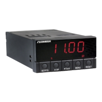
About The Meter 2.4 FRONT OF THE METER SETPTS T/mV MENU RESET Figure 2-1a. Front of meter - pH Controller SETPTS /pH/ORP T/mV MENU RESET Figure 2-1b. Front of meter - pH/ORP Controller METER DISPLAY: -1.9.9.9. or 9.9.9.9. 4-digit 14 segment, 0.54" high Digital LED display LED display with programmable decimal point. -
Page 14: Meter Buttons
About The Meter 2.4.1 METER BUTTONS SETPTS Button In the run mode, this button will sequentially recall the previous setpoint settings. As necessary, use the /pH and /mV buttons to alter these settings, then press the SETPTS button to store new values. Unless you press the SETPTS, /pH, or /mV button within 20 seconds, the meter will... - Page 15 About The Meter 2.4.1 METER BUTTONS (Continued) MENU Button In the run mode, press the MENU button to terminate the current measuring process and enter you into the configuration mode. In the configuration mode, press the MENU button to store changes in the nonvolatile memory and then advance you to the next menu item.
-
Page 16: Front Panel Button Lockout
About The Meter 2.5 FRONT-PANEL BUTTON LOCK OUT (For Security Purposes) 2.5.1 Jumper Lock Out To lock all front-panel buttons, remove the S3-A jumper (refer to Figure 3-2). To lock the MENU button only, verify that the S3-B jumper is removed, then install the S3-A and S3-E jumpers (refer to Table 3-1). -
Page 17: Back Of Meter
About The Meter 2.6 BACK OF THE METER Figure 2-2 shows the label describing the connectors on the back of the meter. Table 2-1 on the following page gives a brief description of each connector at the back of the meter. -
Page 18: Connector Description
About The Meter 2.6 BACK OF THE METER (Continued) Table 2-2. Connector Description Connector Description TB1-1 Setpoint 1: Normally Open (N.O.1) connection TB1-2 Setpoint 1: Normally Closed (N.C.1) connection TB1-3 Setpoint 1: Common (COM1) connection TB1-4 Setpoint 2: Normally Open (N.O.2) connection TB1-5 Setpoint 2: Normally Closed (N.C.2) connection TB1-6... -
Page 19: Disassembly
About The Meter 2.7 DISASSEMBLY You may need to open up the meter for one of the following reasons: • To check or change the 115 or 230 Vac power jumpers. • To install or remove jumpers on the main board. Disconnect the power supply before proceeding. -
Page 20: Getting Started
Getting Started SECTION 3. GETTING STARTED Caution: The meter has no power-on switch, so it will be in operation as soon you apply power. If you power off/on the meter, or perform a hard reset (press the RESET button twice), the meter shows “RST”, followed by "PH". -
Page 21: Main Board Jumpers
Getting Started 3.3 MAIN BOARD JUMPERS Figure 3-2 shows the location jumper positions on the main board. Version with Non-Removable connectors. DISPLAY BOARD Newer version with upper & lower level pull-out MAIN connector plugs BOARD TP1-6 TP1 TP2 TP3 TP4 TP5 TP6 Figure 3-2. -
Page 22: Jumper Functions
Getting Started 3.3 MAIN BOARD JUMPERS (Continued) S1 jumper is for factory use only. Do not install or remove them. S2 jumper allows you to use the meter without ATC. S3 jumpers are used for the following: (Refer to Figure 3-2) To enable or disable the front panel push-buttons To allow for an extremely low resistance load for analog output To disable the MENU button... -
Page 23: Panel Mounting
Getting Started 3.4 PANEL MOUNTING CONNECTOR LABEL PRODUCT CASE LABEL GASKET FRONT BEZEL Figure 3-4. Meter - Exploded View PANEL THICKNESS 1. Cut a hole in your panel, as 6,4 (.25) MAX shown in Figure 3-4. For 0,8 (.03) MIN specific dimensions refer to Figure 3-5. -
Page 24: Connecting Sensor Inputs
Getting Started 3.5 CONNECTING SENSOR INPUTS pH INPUT* 1 2 3 4 5 6 7 8 9 10 11 12 1* 2* 3* * = CONNECT TO LOW VOLTAGE LIMITED ENERGY CIRCUITRY ONLY. Figure 3-6. pH and RTD Input Connections... -
Page 25: Connecting Main Power
Getting Started 3.6 CONNECTING MAIN POWER Connect the ac main power connections as shown in Figure 3-7. Warning: Do not connect AC power to your device until you have completed all input and output connections. This device must only be installed by a specially trained electrician with corresponding qualifications. -
Page 26: Connecting Analog And Relay Outputs
Getting Started 3.6 CONNECTING MAIN POWER (Continued) Connect the dc main power connections as shown in Figure 3-8. pH INPUT 1 2 3 4 5 6 7 8 9 10 11 12 1 2 3 + DC - DC DC POWER Figure 3-8. -
Page 27: Analog Output Connections
Getting Started 3.7 CONNECTING ANALOG AND RELAY OUTPUTS (Continued) pH INPUT 1 2 3 4 5 6 7 8 9 10* 11*12* 1 2 3 * = CONNECT TO LOW VOLTAGE LIMITED ENERGY CIRCUITRY ONLY. Figure 3-10. Analog Output Connections 1* 2* 3* 1 2 3 4 pH INPUT... -
Page 28: Configuring The Meter
Configuring The Meter SECTION 4. CONFIGURING THE METER • Refer to Table 7-1 for a summary list of menu configuration. • Factory defaults are in bold and italics. • The Unit of Measurement for setpoints, deadbands, and read 1/read 2 (Output Scale and Offset) is all in Millivolts. -
Page 29: Selecting A Decimal Point Position (Dec.p)
Configuring The Meter 4.2 SELECTING A DECIMAL POINT POSITION (“DEC.P”) To select a decimal point display position, follow these steps: Press the MENU button until the meter shows “DEC.P”. Press the T/mV button. The meter shows one of the following: •... -
Page 30: Using Reading Configuration (Rd.cf)
Configuring The Meter 4.3 USING READING CONFIGURATION (“RD.CF”) To select the calibration mode and units of measurement, follow these steps: Press the MENU button until the meter shows “RD.CF”. Press the T/mV button. The meter shows one of the following: •... -
Page 31: Performing Two-Point Calibration (Cal.2)
Configuring The Meter 4.4 PERFORMING TWO-POINT CALIBRATION (“CAL.2”) Only buffer solutions of 4, 7 and 10 are acceptable. IF the buffer value is not accepted, the meter will display a flashing “PH.ER“. Two-point calibration should be performed with two combinations of two buffer solutions (4 and 7, or 7 and 10). -
Page 32: Performing Three-Point Calibration (Cal.3)
Configuring The Meter 4.5 PERFORMING THREE-POINT CALIBRATION (“CAL.3”) Only buffer solutions of 4, 7 and 10 are acceptable. IF the buffer value is not accepted, the meter will display a flashing “PH.ER“. Place your electrode into the pH buffer solution. Press the MENU button until the meter shows “CAL.3”... -
Page 33: Using Setpoint 1 Configurations (S1.Cf)
Configuring The Meter 4.6 USING SETPOINT 1 CONFIGURATIONS (“S1.CF”) You may use Setpoint 1 Configuration for the following: • To set setpoint 1’s active band above or below your chosen value • To select whether setpoint 1’s operation is latched or unlatched 4.6.1 Setting Setpoint 1's Active Band Press the MENU button until the meter shows “S1.CF”. -
Page 34: Using Setpoint 2 Configuration (S2.Cf)
Configuring The Meter 4.7 USING SETPOINT 2 CONFIGURATION (“S2.CF”) You may use Setpoint 2 Configuration for the following: • To set setpoint 2’s active band above or below your chosen value • To select whether setpoint 2’s operation is latched or unlatched 4.7.1 Setting Setpoint 2's Active Band Press the MENU button until the meter shows “S2.CF”. -
Page 35: Setting The Setpoint 1 Deadband (S1.Db)
Configuring The Meter 4.8 SETTING THE SETPOINT 1 DEADBAND (“S1.DB”) Factory default deadband is 001.0. The deadband’s resolution value depends upon the decimal point position previously set-up in Section 4.2. The minimum deadband setting should be no less than 0.1 pH. To change the deadband (hysteresis) of setpoint 1, follow these steps: Press the MENU button until the meter shows “S1.DB”. -
Page 36: Relay Output Triggering Example
Configuring The Meter Figure 4-1. Relay Output Triggering Example SETPOINT SIGNAL LEVEL ACTIVE BELOW ACTIVE ABOVE DEADBAND SETPOINT SIGNAL LEVEL ACTIVE BELOW ACTIVE ABOVE WITH DEADBAND 3 WITH DEADBAND 3 NOTE: DEADBAND WORKS AS HYSTERISIS SETPOINT SIGNAL LEVEL ACTIVE BELOW LATCHED ACTIVE ABOVE LATCHED To reset latched alarms you must: 1. -
Page 37: Using Output Configuration (Ot.cf)
Configuring The Meter 4.10 USING OUTPUT CONFIGURATION (OT.CF) Use Output Configuration to select the following: • To enable or disable the analog output • To determine if the analog output is current or voltage 4.10.1 Enabling or Disabling the Analog Output To enable or disable the analog output, follow these steps: Press the MENU button until the meter shows “OT.CF”. -
Page 38: Selecting Analog Output As Ph Or Orp (For Ph/Orp Controllers Only)
Configuring The Meter 4.10.3 Selecting Analog Output as pH or ORP( for pH/ORP Controllers only) Press the T/mV button. The meter shows one of the following: • “O.3=P" (Analog Output assigned to pH) • “O.3=O” (Analog Output assigned to ORP) Press the /pH/ORP button to toggle between available choices. -
Page 39: Configuring Temperature (C Or F-Temp)
Configuring The Meter 4.11 CONFIGURING TEMPERATURE (C or F - “TEMP”) If you have selected “MANU” in “A.T.C.” menu item (Section 4.1), then you have to specify the constant temperature value. Maximum/minimum values are 0 to 199.9 for C or 0 to 398.0 for F. Press the MENU button until the meter shows “TEMP”. -
Page 40: Using Output Scale And Offset (Ot.s.o)
Configuring The Meter 4.12 USING OUTPUT SCALE AND OFFSET (OT.S.O) Output Scale and Offset (“OT.S.O”) scales your analog output to be equal to the meter's display and/or any engineering units you require. You may scale the output for direct (4-20 mA, 0-10 V, etc) or reverse acting (20-4 mA, 10-0 V, etc). Press the MENU button until the meter shows “OT.S.O”. - Page 41 Configuring The Meter 4.12 USING OUTPUT SCALE AND OFFSET (OT.S.O) (Continued) Press the T/mV button. The meter shows the last stored High pH number with flashing 4th digit. Press the /pH button to change the value of the flashing digit. If you continue to press the /pH button, the flashing digit's value continues to change.
-
Page 42: Example For Output Scale And Offset
Configuring The Meter 4.12.1 Example for Output Scale and Offset You want to send 4-20 mA output for 0 to 14 pH value (default). The meter has 0.01 pH resolution. Complete the following steps: Press the MENU button until the meter shows “OT.S.O”. Press the T/mV button. -
Page 43: Selecting Setpoint Values
Selecting Setpoint Values SECTION 5. SELECTING SETPOINT VALUES Follow the steps below to select values for Setpoint 1 and Setpoint 2. Press the SETPTS button. The meter momentarily shows “SP1” (Setpoint 1), followed by the last stored value with flashing 4th digit. The factory default for “SP1”... -
Page 44: Display Messages
Display Messages SECTION 6. DISPLAY MESSAGES Table 6-1. Display Messages MESSAGE DESCRIPTION Hydrogen Potential Hard (power on) reset A.T.C. Temperature Compensation Mode DEC.P Decimal point RD.CF Reading configuration S1.CF Setpoint 1 configuration S2.CF Setpoint 2 configuration S1.DB Setpoint 1 deadband S2.DB Setpoint 2 deadband OT.CF... -
Page 45: Menu Configuration Displays
Menu Configuration Displays SECTION 7. MENU CONFIGURATION DISPLAYS Table 7-1. Configuration Menu (Defaults in Bold and Italics) MENU T/mV A.T.C. METR: Metered - default Temperature Compensation Show A.T.C. choices: MANU: Manually Mode OFF: Constant 25ºC DEC.P FFFF. Decimal Point Show decimal point position FFF.F FF.FF RD.CF... - Page 46 Menu Configuration Displays SECTION 7. MENU CONFIGURATION DISPLAYS Table 7-1. Configuration Menu (Continued) (Defaults in Bold and Italics) MENU T/mV OT.CF D: Disabled Output Configuration E: Enabled Analog Output Option V: Voltage Analog out C: Current Analog out OT.S.O Output Scale & Offset Change flashing digit’s value Enter new value &...
-
Page 47: Run Mode Displays
Menu Configuration Displays SECTION 7. MENU CONFIGURATION DISPLAYS Table 7-2. Run Mode Displays DISPLAY T/mV RESET Description TEMP Shows temperature Temperature value of input Reading signal. Press again to show mV value of input signal. Shows mV value of VOLT input signal. -
Page 48: Setpoint Configuration Displays
Setpoint Configuration Displays SECTION 8. SETPOINT CONFIGURATION DISPLAYS Table 8-1. Setpoint Configuration Displays MENU T/mV DESCRIPTION SP 1 Scroll right one Change flashing Select from -1999 Setpoint 1 digit digit’s value through 9999 SP 2 Scroll right one Change flashing Select from -1999 Setpoint 2 digit... -
Page 49: Specifications
Specifications SECTION 9. SPECIFICATIONS INPUT SIGNAL pH and Volt Specification Range: - 2.00 to 16.00 pH (-620 to +620 mV) Resolution: 1, 0.1, 0.01 pH From: -199.9 to 620.0 mV: 0.1 mV From: -200 to -620: 1 mV Accuracy: ± 0.01 pH (± 0.1 mV) Calibration: Two or Three Point Temperature Compensation:... -
Page 50: Sec
Specifications SECTION 9. SPECIFICATIONS (Continued) ANALOG TO DIGITAL Technique: Dual Slope Internal Resolution: 15 bits Read Rate: 3 per second for pH; 1 per second for Temperature RELAY OUTPUTS 2 Form "C" on/off relays. Configurable for latched and unlatched by software. Max current: 5 A, resistive load Max voltage: 250 Vac or 30 Vd ANALOG OUTPUT... -
Page 51: Panel Cutout
Specifications SECTION 9. SPECIFICATIONS (Continued) INPUT POWER INFORMATION AC units 115/230 V~(AC) ±10%, 50/60 Hz 7 W max, power consumption (Non-Isolated Analog Output) 8 W max, power consumption (Isolated Analog Output) DC units 10-32 Vdc 6 W max, power consumption (Non-Isolated Analog Output) 7 W max, power consumption (Isolated Analog Output) External Fuse Protection Recommended: IEC 127-2/III... - Page 52 Specifications SECTION 9. SPECIFICATIONS (Continued) 48,0 (1.89) 96,0 (3.78) FRONT BEZEL 20,3 (.80) RETAINER CASE REAR COVER TOP VIEW SIDE VIEW PANEL THICKNESS 6,4 (.25) MAX 0,8 (.03) MIN R(.06) 45,00 + 0,61/-0,00 (1.772 + .024/–.000) 4 PLCS 92,00 + 0,81/–0,00 (3.622 + .032/–.000) NOTE: Dimensions in Millimeters (Inches) Figure 9-1.
-
Page 53: Factory Preset Values
Factory Preset Values SECTION 10. FACTORY PRESET VALUES Table 10-1. Factory Preset Values MENU ITEM FACTORY PRESET VALUES A.T.C. Temperature Compensation: METR DEC.P Decimal Point Position: FFF.F RD.S.O Reading Scale and Offset: 4-20 mA dc = 0-1000 RD.CF Reading Configuration: R.1=3 (3 Point Calibration) R.2=C (Degree Celsius) S1.CF... -
Page 54: Ce Approval Section
CE APPROVALS INFORMATION This product conforms to the EMC directive 89/336/EEC amended by 93/68/EEC, and with the European Low Voltage Directive 72/23/EEC. Electrical Safety EN61010-1:2001 Safety requirements for electrical equipment for measurement, control and laboratory. Double Insulation Pollution Degree 2 Dielectric withstand Test per 1 min •... - Page 55 WARRANTY/DISCLAIMER OMEGA ENGINEERING, INC. warrants this unit to be free of defects in materials and workmanship for a period of one (1) year from the date of purchase. In addition to OMEGA’s standard warranty period, OMEGA Engineering will extend the warranty period for four (4) additional years if the warranty card enclosed with each instrument is returned to OMEGA.
- Page 56 Where Do I Find Everything I Need for Process Measurement and Control? OMEGA…Of Course! Shop on line at www.omega.com TEMPERATURE Thermocouple, RTD & Thermistor Probes, Connectors, Panels & Assemblies Wire: Thermocouple, RTD & Thermistor Calibrators & Ice Point References Recorders, Controllers & Process Monitors...
Need help?
Do you have a question about the PHCN-37 and is the answer not in the manual?
Questions and answers