Table of Contents
Advertisement
Quick Links
Advertisement
Table of Contents
Troubleshooting

Related Manuals for CPG Compuprint SP 40

Summary of Contents for CPG Compuprint SP 40
- Page 1 SP 40 MAINTENANCE MANUAL...
-
Page 3: Table Of Contents
Maintenance Manual SP 40 TABLE OF CONTENTS Page Preface Chapter 1 General Information Overview Scope of the Product Main Features Printer Parts Product Structure 1.5.1 Mechanism and Electromechanical devices 1.5.2 Electronics Technical Specifications Maintaining Parameters Chapter 2 Removals Overview Covers 2.2.1 Top Cover 2.2.2... - Page 4 Maintenance Manual SP 40 TABLE OF CONTENTS cont’d Page Chapter 3 Operability and Configuration Overview Operability 3.2.1 Operator Panel 3.2.2 Function keys 3.2.3 Leds Printer Set-up Mode by Operator Panel 3.3.1 Print of Self Test Page 3.3.2 Printer Configuration 3.3.2.1 Print of the Setup Forms 3.3.2.2 Filling in the Printer Setup Forms...
- Page 5 Maintenance Manual SP 40 TABLE OF CONTENTS cont’d Page Chapter 5 Test & Diagnostic Overview How to run T&D (with Standard Operator Panel) General Rules for T&D Operations T&D USER Tests Description Step by Step T&D Mode Flow Chart Step by Step T&D Mode Sequential Table T&D Errors Handling 5.7.1 Led Meaning during T&D Error Condition...
- Page 6 Maintenance Manual SP 40 TABLES Page Table 1.1 Printer Specification Summary Table 3.1 O.P. keys meaning Table 3.2 O.P. Leds meaning Table 3.3 Configuration Form Parameters description Table 3.4 Program 1 (Program 2) Form Parameters description Table 4.1 Not-recoverable leds errors code N° Table 4.2 Not-recoverable errors error table Table 4.3...
- Page 7 Maintenance Manual SP 40 ILLUSTRATIONS Page Fig. 1.1 Front View Fig. 1.2 Rear View (Standard model) Fig. 1.4 Rear View (LAN model) Fig. 1.3 Inside View Fig. 1.5 Lay-out Electronic Parts Fig. 1.6 Lay-out Electromechanical Parts Fig. 2.1 Open Top Cover Fig.
- Page 8 Maintenance Manual SP 40 ILLUSTRATIONS Page Fig. 3.12a Initial mask for SP40setup installation Fig. 3.12b Other mask for SP40setup installation Fig. 3.12c Other mask for SP40setup installation Fig. 3.12d Other mask for SP40setup installation Fig. 3.12e Other mask for SP40setup installation Fig.
- Page 9 Maintenance Manual SP 40 ILLUSTRATIONS Page Fig. 8.1 Gap Adjustment Fig. 8.2 Print Head Gap versus Platen Fig. 8.3 Paper Belt Adjustment Fig. 8.4 Carriage Belt Adjustment Fig. 8.4 Selector Cam Adjustment Rev. 005 Index...
- Page 10 Maintenance Manual SP 40 Page intentionally left blank Rev. 005 Index...
-
Page 11: Preface
Maintenance Manual SP 40 Preface Rev. AE (005) September 2005 Rev. AD (004) April 2005 Rev. AC (003) May 2004 Rev. AB (002) January 2004 Rev. AA (001) June 2003 This Maintenance Manual focuses on the maintenance activities on the printer SP 40. All defects originated by incorrect paper insertion, wrong menu setting or mistaken controls commands, are not covered by this document to avoid duplication of informations available on the USER MANUAL forwarded to each end user within printer package. -
Page 12: Fcc Regulations
Maintenance Manual SP 40 FCC Regulations Note: This equipment has been tested and found to comply with the limits for a Class B digital device, pursuant to Part 15 of the FCC Rules. These limits are designed to provide reasonable protection against harmful interference in a residential installation. -
Page 13: General Information
Maintenance Manual SP 40 Chapter 1 General Information Overview This section describes the product and its intrinsecal main characteristics.. Scope of the Product The product is intended to satisfy most of the counter applications in a ergonomic environment. It is designed for versatile and reliable paper handling. A specialized flat-bed mechanism allows paper to be fed without bending: in this way special documents, such as multiple invoices, postcards, labels, tickets can be trouble-free printed. -
Page 14: Printer Parts
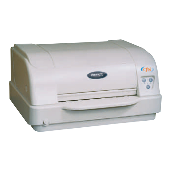
Maintenance Manual SP 40 Printer Parts Printer Cover Operator Panel Paper Stand Power-on Push-button Figure 1.1 - Front View Power Cable Connector Serial Interface Cable Connector Parallel Interface Cable Connector Figure 1.2 - Rear View (standard model) Rev. 005 Chapter 1 General... - Page 15 Maintenance Manual SP 40 Figure 1.3 - Rear View (LAN model) Printhead Print Head Assembly Print Area Paper Jam Removal Cog-wheel Figure 1.4 - Inside View Rev. 005 Chapter 1 General...
-
Page 16: Product Structure
Maintenance Manual SP 40 Product Structure 1.5.1 Mechanism and Electromechanical Devices The basic mechanism has been designed to support a flat-bed path oriented to an high reliability of the paper handling. Paper Handling A stepper motor, supporting 1/180" paper step together with a minipitch belt, provides the movement to the paper alignment and pressing front and rear rollers. -
Page 17: Electronics
Maintenance Manual SP 40 1.5.2 Electronics Electronic parts of the printer are: • Power Supply autoswitching type. • Controller Board including parallel and 9 pin serial interface connector for standard model. On the controller are also present the flash memory with firmware and generator on it. This structure is intended to make easy update the controller with a new firmware version through a downloading operation. - Page 18 Maintenance Manual SP 40 Here below the lay-out of the Electronic parts (the LAN and the USB can be installed one per time). BOARD CONTROLLER BOARD BOARD BACK PANEL ENGINE BOARD POWER SUPPLY O.P. BOARD Figure 1.5 - Lay-out Electronic parts Rev.
- Page 19 Maintenance Manual SP 40 Figure 1.6 - Lay-out Electromechanical parts Rev. 005 Chapter 1 General...
-
Page 20: Technical Specifications
Maintenance Manual SP 40 Technical Specifications Printing Technology Print head: ER24W 24 pin – Ø 0,25 mm Print head life 400 million characters Resolution: 360 x 360 dpi (HxV) Line Length (@ 10 cpi) 94 columns (cut sheets) Printing Speed 400 cps @ 10 cpi (Draft) 133 cps @ 10 cpi (LQ) Emulation... - Page 21 Maintenance Manual SP 40 Special Functions Automatic Gap Adjustment (AGA) Auto Alignment Auto Border Recognition Ribbon Life 4 million characters (black) Reliability MTBF: 10,000 hours Duty cycle 28000 pages/month Physical Dimensions & Weight 400 (W) x 295 (H) x 200 (D) mm <...
-
Page 22: Maintaining Parameters
Maintenance Manual SP 40 1.7 Maintaining Parameters MTTR The Mean Time To Repair is the estimated mean time to repair the printer at Optimum Replaceable Unit (ORU) level. For this printer the MTTR is 16 minute and includes: Identifying the faulty ORU Changing the ORU Cleaning Testing... -
Page 23: Removals
Maintenance Manual SP 40 Chapter 2 Removals Overview This section describes the removal and installation procedures of the major printer parts. Danger notices warn against personal injury that is lethal or extremely hazardous. Caution notices warn against personal injury that is neither lethal nor extremely hazardous. Attention notices warn against damage to machine, equipment or programs. -
Page 24: Covers
Maintenance Manual SP 40 Covers DANGER : To prevent serious personal injury from electrical shock always turn the printer off and unplug the power cable before remove the cover parts. ATTENTION: The electronic parts of this printer are easily damaged by Electronic Static Discharge(ESD). Ensure that ESD protection devices and procedures, including the static discharge wrist wrap, are used while working on this printer. - Page 25 Maintenance Manual SP 40 Figure 2.1 - Open Top Cover Figure 2.2 - Cover Removals Rev. 005 Chapter 2 Removals...
-
Page 26: Print Head
Maintenance Manual SP 40 Print Head DANGER : To prevent serious personal injury from electrical shock always turn off the printer and unplug the power cable before remove the print head. CAUTION: The print head may have hot surface. Wait for it to cool down. ATTENTION: Only the two allen screws have to be unscrewed to remove the print head. - Page 27 Maintenance Manual SP 40 Figure 2.4 - Ribbon Guide Figure 2.5 Print Head Removal Rev. 005 Chapter 2 Removals...
-
Page 28: Mechanical Assy
Maintenance Manual SP 40 Mechanical Assy To Remove: Remove the top and the main cover (see chapter 2.2). Unplug the seven cables from the connector on the front side of the engine board. From right to left, the connectors are op. panel, ribbon sensor, paper motor, home sensor, selector motor, carriage motor. -
Page 29: Electronic Boards
Maintenance Manual SP 40 Electronic Boards DANGER : To prevent serious personal injury from electrical shock always turn the printer off and unplug the power cable before to remove the engine and the controller board. ATTENTION: The electronic parts of this printer are easily damaged by Electronic Static Discharge(ESD). Ensure that ESD protection devices and procedures, including the static discharge wrist wrap, are used while working on this printer. -
Page 30: Controller Board
Maintenance Manual SP 40 2.5.3 Controller Board Controller board is item 10 of figure 2.7. To Remove: Remove the engine board following the chapter 2.5.2 described before. Remove the two screws (item 30) fixing the parallel I/F connector from the rear side of the printer. Remove the two screws (item 13) fixing the serial I/F connector from the rear side of he printer. - Page 31 Maintenance Manual SP 40 Figure 2.7 - Boards Removal Rev. 005 Chapter 2 Removals...
- Page 32 Maintenance Manual SP 40 Page intentionally left blank Rev. 005 Chapter 2 Removals...
-
Page 33: Operator Panel
Maintenance Manual SP 40 Operator Panel DANGER : To prevent serious personal injury from electrical shock always turn the printer off and unplug the power cable before to remove the operator panel. ATTENTION: The electronic parts of this printer are easily damaged by Electronic Static Discharge(ESD). Ensure that ESD protection devices and procedures, including the static discharge wrist wrap, are used while working on this printer. -
Page 34: Motors Assy
Maintenance Manual SP 40 Motors Assy 2.7.1 Carriage Motor Assy DANGER : To prevent serious personal injury from electrical shock always turn the printer off and unplug the power cable before to remove the carriage motor assy. Carriage motor is item 66 of figure 2.9. It is assembled together whith its support (item 63 of figure 2.9) and ribbon drive assy (item 67 of figure 2.9). - Page 35 Maintenance Manual SP 40 Figure 2.9 - Carriage Motor Assy removal Rev. 005 Chapter 2 Removals...
-
Page 36: Selector Motor Assy
Maintenance Manual SP 40 2.7.3 Selector Motor Assy DANGER : To prevent serious personal injury from electrical shock always turn the printer off and unplug the power cable before to remove the selector motor assy. Selector motor assy is item 57 of figure 2.10. To Remove: Remove the top and the main cover assy (see chapter 2.2). - Page 37 Maintenance Manual SP 40 Figure 2.10 - Selector and Paper Motor removal Rev. 005 Chapter 2 Removals...
-
Page 38: Home Sensor Assy
Maintenance Manual SP 40 Home Sensor Assy DANGER : To prevent serious personal injury from electrical shock always turn the printer off and unplug the power cable before to remove the paper motor assy. Home sensor assy is item 69 of figure 2.11 and is fixed on the vertical frame of the printer. To Remove: Remove the top and the main cover assy (see chapter 2.2). -
Page 39: Ribbon Sensor Assy
Maintenance Manual SP 40 Ribbon Sensor Assy DANGER : To prevent serious personal injury from electrical shock always turn the printer off and unplug the power cable before to remove the paper motor assy. Ribbon sensor assy is item 99 of figure 2.12 and is fixed on the upper side of the right frame of the printer. To Remove: Remove the top and the main cover assy (see chapter 2.2). -
Page 40: Ribbon Drive Assy
Maintenance Manual SP 40 2.10 Ribbon Drive Assy DANGER : To prevent serious personal injury from electrical shock always turn the printer off and unplug the power cable before to remove the ribbon drive assy. Ribbon drive assy is item 67 of figure 2.13. It is fixed on the support of the carriage motor assy. To remove the ribbon drive assy, firstly remove the assembly and then remove the ribbon drive assy from the support. - Page 41 Maintenance Manual SP 40 Figure 2.13 - Ribbon Drive Removal Rev. 005 Chapter 2 Removals...
-
Page 42: Carriage Assy
Maintenance Manual SP 40 2.11 Carriage Assy DANGER : To prevent serious personal injury from electrical shock always turn the printer off and unplug the power cable before to remove the carriage assy. ATTENTION: DO NOT REMOVE THE GREEN LEVERS BEFORE TO HAVE REMOVED THE TWO BIG SPRINGS (items 86 and 87 of figure 2.14) ON THE REAR SIDE OF THE PRINTER. - Page 43 Maintenance Manual SP 40 Exploded View Fifure 2.14 - Carriage Assy Removal Rev. 005 Chapter 2 Removals...
-
Page 44: Mylar Bar Assy
Maintenance Manual SP 40 2.12 Mylar Bar Assy DANGER : To prevent serious personal injury from electrical shock always turn the printer off and unplug the power cable before to remove the mylar bar assy. Mylar bar assy is item 34 of figure 2.15. To Remove: Remove the top and the main cover assy (see chapter 2.2). - Page 45 Maintenance Manual SP 40 Figure 2.15 - Mylar Bar Removal Rev. 005 Chapter 2 Removals...
-
Page 46: Rear Roller Assy
Maintenance Manual SP 40 2.13 Rear Roller Assy DANGER : To prevent serious personal injury from electrical shock always turn the printer off and unplug the power cable before to remove the rear roller assy. Rear roller assy are item 71 of figure 2.16. Rear roller assy is composed by a couple of roller. On the printer are installed three rear roller assy together ingaged by plastic couplings. - Page 47 Maintenance Manual SP 40 Figure 2.16 - Rear Roller Assy Removal Rev. 005 Chapter 2 Removals...
-
Page 48: Front Roller Assy
Maintenance Manual SP 40 2.14 Front Roller Assy DANGER : To prevent serious personal injury from electrical shock always turn the printer off and unplug the power cable before to remove the front roller assy. Front roller assy are item 45 of figure 2.17. Front roller assy is composed by a double couple of roller. Each of the couple has a metal roller near a rubber one. - Page 49 Maintenance Manual SP 40 Exploded View Figure 2.17 - Front Roller Assy Removal Rev. 005 Chapter 2 Removals...
-
Page 50: Selector Cam
Maintenance Manual SP 40 2.15 Selector Cam DANGER : To prevent serious personal injury from electrical shock always turn the printer off and unplug the power cable before to remove the selector cam. Selector cam is item 28 of figure 2.18 To Remove: Remove the top and the main cover assy (see chapter 2.2). - Page 51 Maintenance Manual SP 40 Figure 2.18 - Selector Cam Removal Rev. 005 Chapter 2 Removals...
-
Page 52: Lower Roller Assy (Rear Side)
Maintenance Manual SP 40 2.16 Lower Roller Assy (Rear Side) DANGER : To prevent serious personal injury from electrical shock always turn the printer off and unplug the power cable before to remove the lower roller assy. Lower roller assy installed under the rear bed of the printer is item 7 of figure 2.19. To Remove: Remove the top and the main cover (see chapter 2.2). -
Page 53: Lower Roller Assy (Front Side)
Maintenance Manual SP 40 2.17 Lower Roller Assy (Front Side) DANGER : To prevent serious personal injury from electrical shock always turn the printer off and unplug the power cable before to remove the lower roller assy. Lower roller assy installed under the front bed of the printer is item 7 of figure 2.20. To Remove: Remove the top and the main cover assy (see chapter 2.2). -
Page 54: Sensor Board And Sensor Cable
Maintenance Manual SP 40 2.18 Sensor Board and Sensor Cable DANGER : To prevent serious personal injury from electrical shock always turn the printer off and unplug the power cable before to remove the sensor board or its cable. Sensor board and sensor cable are respectively item 10 and 98 of figure 2.21. They are installed under the front bed of the printer. - Page 55 Maintenance Manual SP 40 Figure 2.21 - Sensor Board and Sensor Cable Removal Rev. 005 Chapter 2 Removals...
-
Page 56: Platen Assy
Maintenance Manual SP 40 2.19 Platen Assy DANGER : To prevent serious personal injury from electrical shock always turn the printer off and unplug the power cable before to remove the platen assy. Platen assy includes items 17, 18 and 94 of figure 2.22. To Remove: Remove the top and the main cover assy (see chapter 2.2). - Page 57 Maintenance Manual SP 40 Figure 2.22 - Platen Assy Removal Rev. 005 Chapter 2 Removals...
-
Page 58: Print Head Cables
Maintenance Manual SP 40 2.20 Print Head Cables DANGER : To prevent serious personal injury from electrical shock always turn the printer off and unplug the power cable before to remove the print head cables. Print head cables are item 95 of figure 2.23 and are protected by the mylar film (item 96 of figure 2.23). To Remove: Remove the top and the main cover assy (see chapter 2.2). -
Page 59: Operability And Configuration
Maintenance Manual SP 40 Chapter 3 Operability and Configuration 3.1 Overview This chapter describes the main operability and configuration functionalities. For complete and detailed description, please refer to the specific User manual. The control panel provides access to used functions and to set-up the printer for software environment. The control panel works in different ways according to the printer operating status 3.2 Operability The operability of this printer is done through a specific operator panel. -
Page 60: Function Keys
Maintenance Manual SP 40 3.2.2 Function Keys NORMAL MODE SETUP MODE SPECIAL MODE STATION1 Pressing this key, when the printer is offline, When the Printer is in the Pressed while powering on or when the printer is online and no print Printer Setup mode, pressing the printer on with ON LINE data are in the buffer, the printer ejects the... -
Page 61: Printer Set-Up Mode By Operator Panel
Maintenance Manual SP 40 Printer Set-Up Mode by Operator Panel The following figure shows the actions flow to configure the printer using the operator panel. Next chapters details each step. Figure 3.2 - Set-up Mode flow-chart Rev. 005 Chapter 3 Operabilty and Configuration... -
Page 62: Print Of Self Test Page
Maintenance Manual SP 40 3.3.1 Print of Self Test Page To understand if the printer has been correctly installed a self test page may be printed following these steps: 1. Press the ON LINE key while powering the printer on and hold the key pressed until all leds turn briefly on. 2. -
Page 63: Printer Configuration
Maintenance Manual SP 40 3.3.2 Printer Configuration The steps necessary to configure the printer are the following: Printing of the Setup forms Filling in of the printed forms. Reading of the filled in modules to store the parameters in NVM. REMARK: If the printed forms are available also in photocopies (not reduced), only the step 3 is necessary to configure the printer. -
Page 64: Filling In The Printer Setup Forms
Maintenance Manual SP 40 The printer setup forms contain all printer parameters and the values that can be set. The current value is indicated by an asterisk (*). Each Setup form is identified by a marker in the upper left corner of the page as follows: Configuration Setup Program 1 Program 2... -
Page 65: Setup Forms And Parameters
Maintenance Manual SP 40 3.3.2.4 Setup Forms and Parameters The following figures and tables are the setup forms printed by the printer with their meaning. The Program 2 is identical to the Program 1 except for the black markers as indicated in figure 3-4. Note: the parameters can be changed in different version of the Code, always see the User Manual for the correct set- up parameters. -
Page 66: Table 3.3 Configuration Form Parameters Description
Maintenance Manual SP 40 Setup Parameter Values Description RESTORE TO MFG The selected values are not set to factory defaults. The values set in all printer setups are reset to factory default values. config The values set in the configuration setup are reset to factory default values. progr. - Page 67 Maintenance Manual SP 40 EDGE DETECTION Normal*, Safe When safe is select the edge detection is always from outside to inside of the paper. SAFE BOTTOM EDGE No, yes When yes sets the bottom printing margin is 6.6mm instead of 2.8mm. GET EDGE QUOTE 0/4”*, 1/4”, 2/4”, 3/4”, 4/4”, 5/4”, Sets the position in which the left paper edge is checked.
- Page 68 Maintenance Manual SP 40 Figure 3.8 - Program 1 Setup Form Rev. 005 Chapter 3 Operabilty and Configuration...
-
Page 69: Table 3.4 Program 1 (Program 2) Form Parameters Description
Maintenance Manual SP 40 Setup Parameter Values Description PROTOCOL EPSON 570, IBM X24E*, X24E Defines the printer protocol. AGM, IBM 2390, OLI. PR40+, OLI. PR2, OLI. PR2845, IBM 4722, IBM 9068 FONT Draft*, Courier, OCR-B, Gothic, Selects the font. Prestige, Present, OCR-A, Script, Boldface DOWNLINE LOADING Disable, enable*... - Page 70 Maintenance Manual SP 40 CODE PAGE CP437*, CP437G, 96GREEK, Selects the character sets for the IBM and EPSON protocols. CP850, CP851, CP852, CP853, CP855, CP857, CP858, CP860, CP862, CP863, CP864, CP865, CP866, CP867, CP876, CP877, CP1098, CP1250, CP1251, CP1252, CP1257, GOST, TASS, MAZOWIA, CP437SL, UKRAIN, KOI8-U, 8859/1, 8859/2, 8859/3, 8859/4,...
-
Page 71: Offset Adjustments
Maintenance Manual SP 40 3.3.2.5 Offset Adjustments For a precise adjustment of the position of the printed characters on a preprinted form, this printer allows to easily adjust the first line and the first printing column as follows: The following sheet will be printed: Figure 3.9 - Offset Tuning Setup Form Rev. - Page 72 Maintenance Manual SP 40 The Vertical Offset Tuning values correspond to 1/60 inches and set the vertical offset of the first print line starting from the default standard position at 1 mm from the upper paper margin. The Horizontal Offset Tuning values correspond to 1/60 inches and set the horizontal offset of the first print line starting from the default standard position at 3 mm from the left paper margin.
-
Page 73: Printer Set-Up Mode By Web Browser (Nic Card)
Maintenance Manual SP 40 Printer Set-Up Mode by Web Browser (NIC board) If the printer has the LAN interface board installed, using an Internet Browser, it is possible monitoring the status of the printer (a virtual operator panel with display shows the messages) and do the remote configuration Setup. The printer has buitl-in html pages. - Page 74 Maintenance Manual SP 40 To assure a security access to the remote configuration, a security Password can be set. Figure 3.11b - System Page of SP40 through web browser In the System page ckick on the Security Setting button. The first time the following screen appears: Figure 3.11c - Security Setting (first time) The User Name is: root The default password is : root...
- Page 75 Maintenance Manual SP 40 The following screen appears. Figure 3.11d - Security Setting Page of SP40 through web browser It is now possible to indicate a password to protect the setting. Click on the submit button, the following scree appears remind you that it is necessary to select Reboot printer in the Printer Reset page to save the changes.
- Page 76 Maintenance Manual SP 40 Figure 3.11g - Configuration Setup Page of SP40 through web browser Figure 3.11h - Program 1/2 Setup Page of SP40 through web browser Rev. 005 Chapter 3 Operabilty and Configuration...
- Page 77 Maintenance Manual SP 40 Figure 3.11i - NIC Setup Page of SP40 through web browser When the parameters of each of the previous tables representing the different Configurations setups have been set as necessary, click on the Submit button at the end of the table. If a password has already been set in the Securiry item, to enter the remote printer configuration mode, you need to type the network password.
-
Page 78: Printer Set-Up Mode Through The Application Sp40Setup (Via Serial I/F)
Maintenance Manual SP 40 Printer Set-Up Mode through the application "SP40setup" (via serial i/F) The SP40 printer can be easily configured through the serial interface, using the SW application tool described here. The printer must be in Setup mode and install the basic FW release 1.78 or later. The SP40SetUp application is stored in the Area Partner of the web in the file SP40setup.zip Download this file from the web and exctract the files from it. -
Page 79: Fig. 3.12C Other Mask For Sp40Setup Installation
Maintenance Manual SP 40 Figure 3.12c - Other mask for SP40setup installation Figure 3.12d - Other mask for SP40setup installation Figure 3.12e - Other mask for SP40setup installation Rev. 005 Chapter 3 Operabilty and Configuration... -
Page 80: Run The Sp40Setup Application
Maintenance Manual SP 40 Figure 3.12f - Other mask for SP40setup installation Figure 3.12g - Other mask for SP40setup installation 3.5.3 Run the SP40Setup application Double click on the icon created in the Program of Windows, and you can get an empty page: Figure 3.13 - Initial mask of the SP40setup application Pressing the button the current printer configuration is read from the printer and it is displayed :... -
Page 81: Fig. 3.14A Read Nvm Mask Of The Sp40Setup Application
Maintenance Manual SP 40 Figure 3.14a - Read NVM mask of the SP40setup application All configuration items are displayed in the same order as they appear in the Printer Setup Forms described in the SP40 User Manual. Please refeer to it for the items description. Using the scroll bar is possible to reach all items and then modify them : Figure 3.14b - Read NVM mask of the SP40setup application In any moment is possible to revert to the actual printer configuration simply pressing the... -
Page 82: Fig. 3.15 Write Nvm Mask Of The Sp40Setup Application
Maintenance Manual SP 40 Pressing the button, the factory default configuration is restored into the printer NVM and showed in the SP40setup window. When all modification are done, the new configuration can be stored in the printer NVM pressing the button. -
Page 83: How To Download To Sp40 An Existing Configuration File
Maintenance Manual SP 40 3.5.4 How to download to SP40 an existing configuration file A configuration file, generated with the SP40 setup tool as previously described, can be simply used to duplicate the same configuration on more printers. SP40 unit has to be powered on in normal mode, connected to the PC through any active interface (Centronics or Serial port). -
Page 84: Print Of Nic Configuration Page
Maintenance Manual SP 40 Print of NIC Configuration Page The complete NIC configuration parameters can be printed by simply press the little button near the Ethernet RJ conenctor for more than 5 seconds with the paper loaded and the printer already powered on. The figure below shows the location of the button and thhe printout. -
Page 85: Service Maintenance
Maintenance Manual SP 40 Chapter 4 Service Maintenance 4.1 Overview This chapter describes how to maintain the printer in order to always obtain the best performances from it. In this chapter it is possible to find also some helps to test printer and to identify defective components using Test &... -
Page 86: Lubrication
Maintenance Manual SP 40 4.5 Lubrication The following point of the mechanical assy should be lubricated when a maintenance activities is done in the printers to avoid any seize in the movement of the parts. • DO NOT LUBRICATE the main shaft, but only clean dirt. Only a drop of oil can be put on the felts inside the carriage if they are dry. -
Page 87: Software Update
Maintenance Manual SP 40 4.8 Software Update The printer has the basic controller FW and the font generator on FLASH device. Also the LAN FW is on flash. This allows an easily up-date of the Code through the parallel, serial or LAN interface. On the Main Board used as spare part, the firmware pre-loaded has to be intended just as a predisposition allowing to load the specific firmware. -
Page 88: Nic Software Update Through Parallel Or Serial Interface
Maintenance Manual SP 40 Updating steps (to download code 1.7x and later) 1. Create a sub-directory and position on it. 2. Copy from the WEB the file SP40_17x.ZIP. 3. Exctract the files. 4. Connect the printer to a PC on the parallel port LPT1 or the serial one COM1. 5. -
Page 89: Lan Parameters Setup Through Parallel Interface
Maintenance Manual SP 40 4.8.3 LAN Parameters Setup through parallel interface The NIC board shipped from the factory has defualt paramaters, therefore before use it it is mandatory to configure the LAN parameters. On the partner area folder of our Web Site in the SP40, firmware folder, the following file is available for the updating of the NIC parameters: SP40LANCFG.ZIP Containing the files:... -
Page 90: Software Update Through Lan Interface
Maintenance Manual SP 40 4.8.4 Software update through LAN interface After the LAN parameters initialization explained in previous chapter 4.7.2, it is possible to send both Basic+CG firmware or NIC firmware through the LAN interface using FTP tool. Download the proper file from the WEB as explained in previous chapters. For the Basic+CG software: SP40_17x.ZIP For the NIC software:... -
Page 91: Troubleshooting
Maintenance Manual SP 40 4.9 Troubleshooting This chapter is intended to help technical people in the fault finder. The recommended sequences for the printer fault detection are: • To observe initializing procedure and led status. • To check power malfunctions. •... -
Page 92: Unrecoverable Errors
Maintenance Manual SP 40 4.9.2.2 Unrecoverable Errors When an error of this kind occurs, the printer is halted and enters in error state. Errors of this kind can be: • SPV FAULT • INTERPRETER ANSWER ERROR • PRINT MANAGER ANSWER ERROR •... - Page 93 Maintenance Manual SP 40 The not recoverable error detection is done in four steps each 1 second of time in which on the leds of the operator panel are represented the error codes with this sequence: 1. Device in failure identification N°. 2.
-
Page 94: Troubleshooting Tables
Maintenance Manual SP 40 4.10 Troubleshooting Tables NOTE: For the electrical value of the electromechanical parts, please refer to chapter 7. 4.10.1 Power malfunction SYMPTOM PROBABLE CAUSE CORRECTIVE ACTION The printer is not powered No AC power is reaching the Check power cord insertion. -
Page 95: Faulty Probability Guide
Maintenance Manual SP 40 4.10.2 Faulty Probability Guide This table resumes some (not all) of the most frequently symptoms of incorrect functionalities that can appear in the normal usage of the printer with their related probable cause and the corrective actions. SYMPTOM PROBABLE CAUSE CORRECTIVE ACTION... -
Page 96: Reset The Consumable Parts
Maintenance Manual SP 40 SYMPTOM PROBABLE CAUSE CORRECTIVE ACTION The paper is not feeder The paper path is not free. Check for the paper path to be free.Open the properly. mechanical assy through the right and the left green levers and remove residual of paper also through the paper knob. -
Page 97: Test & Diagnostic
Maintenance Manual SP 40 Chapter 5 Test & Diagnostic Overview For the field maintenance of this printer, a specific Test & Diagnostic feature has been developed. This feature is built -in the basic firmware of the printer. The version of the T&D is reported in the T&D printout together with the version of the basic FW and (if present) the optional LAN FW. -
Page 98: Table 5.1 General Rules For T&D Operations
Maintenance Manual SP 40 Messages are codified in order to provide a proper identification of: Test execution Test KO Error code Message to operator For the detail see tables on next pages. The general rules condition which can appear are reported in the following table. Type of Operator Message LEDS Note... -
Page 99: T&D User Tests Description
Maintenance Manual SP 40 T&D USER Tests Description TEST# DESCRIPTION OF TEST (from T&D Rel. 1.50) Step By Step Complete mode mode Test of writing/reading of NVM with 55/aa pattern and subsequent storing of T&D2 DEFAULT parameters. Test of reading accessibility and checksum of NVM. T&D3 Test of optional interfaces T&D4... -
Page 100: Step By Step T&D Mode Flow Chart
Maintenance Manual SP 40 Step By Step T&D Mode Flow Chart This is a schematic flow-chart of the whole T&D USER procedure in Step By Step mode. ON LINE STATION 1 IN 3SEC STATION 1 STATION 1 STATION 1 STATION 1 TEST# -1 REPEAT TEST# REPEAT TEST#... -
Page 101: Step By Step T&D Mode Sequential Table
Maintenance Manual SP 40 Step By Step T&D Mode Sequential Table This is a table of the whole T&D USER procedure in sequential Step By Step mode. The column have these meaning: 1) T&D SbS Phases 2) Messages on the Operator Panel with Display. 3) The same message converted on the leds for the standard Operator Panel. - Page 102 Maintenance Manual SP 40 T&D SbS PHASE DISPLAY MESSAGE LEDS PUSHED KEY KEY's ACTION ¥ “REPT LOOP SKIP” ON LINE ON LINE to loop ¡ £ £ STATION 1 STATION 1 to repeat the test STATION 2 STATION 2 to skip the test Optional Board Test “T&D 04 S_B_S”...
- Page 103 Maintenance Manual SP 40 RUNNING TEST DISPLAY MESSAGE LEDS PUSHED KEY KEY's ACTION ¡ “KEY 2 (*) (v) (-)“ LOAD ON LINE to test ¡ ¡ £ The Key 2 ¡ “KEY 3 (-) (v) (*)“ ON LINE ON LINE to test ¡...
- Page 104 Maintenance Manual SP 40 RUNNING TEST DISPLAY MESSAGE LEDS PUSHED KEY KEY's ACTION ¡ Printing Standard “T&D 10 S_B_S” ON LINE A buzzer ON LINE to run ¡ l Pattern Module beep is STATION 1 Test STATION 1 sound to decrement test STATION 2 STATION 2 to increment test...
- Page 105 Maintenance Manual SP 40 RUNNING TEST DISPLAY MESSAGE LEDS PUSHED KEY KEY's ACTION ¡ Printing the error “T&D 12 S_B_S” ON LINE A buzzer ON LINE to run ¡ log Test beep is STATION 1 STATION 1 sound to decrement test STATION 2 STATION 2 to increment test...
-
Page 106: T&D Errors Handling
Maintenance Manual SP 40 T&D Errors Handling When a Test fails in every type of T&D mode, all the four leds (except Power) are lit together and the buzzer sounds a beep every 1 second. Follow these steps: RUNNING TEST DISPLAY MESSAGE LEDS PUSHED KEY... -
Page 107: Led Meaning During T&D Error Condition
Maintenance Manual SP 40 5.7.1 Led Meaning during T&D Error Condition If the operator panel has not the LCD display installed, when the printer recognizes an error, a pressure on LQ key allows to show up to 4 different led combinations (in the meantime the buzzer sound switch from normal to short beep every 1 sec). -
Page 108: Table 5.6 Led Status For Oru In Error
Maintenance Manual SP 40 The table below shows the led condition after the second pressure of ON LINE key (ORU in error) during the test failure detection. Nº O.R.U. LEDS £ ORU 0 £ ORU 1 ¡ £ ORU 2 ¡... -
Page 109: Table 5.7 Led Status For Specific/Common Error Codes
Maintenance Manual SP 40 The table below shows the led condition after the third pressure of ON LINE key (specific/common error codes) during the test failure detection. N° Error Code LEDs Code 1 £ ¡ Code 2 £ ¡ Code 3 £... -
Page 110: T&D Errors Codes
Maintenance Manual SP 40 T&D Errors Codes The executed tests are 11. The table below shows the complete list of tests with description and the O.R.U. (Optimum Replaceable Unit) under test. Nº Test Description Error Code Error Description Reserved Test complete E PROM Writing error Reading error... -
Page 111: Table 5.9 T&D O.r.u. Codes
Maintenance Manual SP 40 O.R.U. Reference Operator Panel Sensors Mechanical Eproms / Flash / Rom Supervisor (s/w) Option (MSRW/ MICR) Scanner (not used) Table 5.9 T&D O.R.U. Codes Error Code Error Meaning Sensors S1 / S2 (PPS) Sensors S3 / S6 (CSLS) Sensor S8 Threshold S8 Sensor S8... -
Page 112: Requested Tools
Maintenance Manual SP 40 Requested Tools For a correct maintenance are necessary the following parts: Single sheet paper 80 gr/m2 (0.1 mm thickness) N.A. RS232 Serial Loop-back T.B.D. Parallel loop-back P.N. 78900884-001 Operator Panel with display (recommended) P.N. 78901347-001 Magnet for Interlock P.N. -
Page 113: Parallel Interface Loop-Back Connector
Maintenance Manual SP 40 5.9.3 Parallel Interface Loop-Back Connector The schematic diagram is the following: BUSYSTR DATA3 DATA2 DATA1 DATA0 DATA4 DATA5 DATA6 DATA7 ACKAUTO SLCTINI FAULT 74HC86 FINGHER SLCTIN CONN. CENT36 LEDR LEDY 74HC374 74HC86 74HC86 1KpF 74HC86 Fig. 5.5 Parallel I/F bi-directional Loop-back Rev. -
Page 114: Analysis Of T&D Printouts
Maintenance Manual SP 40 5.10 Analysis of T&D Printouts 5.10.1 Printing Adjustment Printout (T&D 9) In this test the printer prints three black patterns and with the edge sensor checks and automatically adjusts the following parameters: The standard A4 paper must be loaded. If loading fails the message of "... -
Page 115: Standard Pattern Printout (T&D 10)
Maintenance Manual SP 40 5.10.2 Standard Pattern Printout (T&D 10) In this test the printer prints a patter with a lot of information to check all the correct functionalities. If the T&D9 was previously done and the same sheet used is loaded, the printers automatically prints the whole pattern as indicated in next figure 5.5A, otherwise a blank area appears in correspondance of the T&D19 pattern. - Page 116 Maintenance Manual SP 40 At about 203,2mm (8") from the continuous line printed in the step 1., a pattern with 8 signs under which a check marker which must be signed after the end of the test or a couple of asterisks are printed to mark the current interline.
-
Page 117: Fig. 5.7 Pattern For Printout T&D9+T&D10 Of Standard Model (Reduced)
Maintenance Manual SP 40 Fig. 5.7 Pattern for Printout T&D9+T&D10 of Standard Model (reduced) Rev. 005 Chapter 5 Test & Diagnostic... -
Page 118: Monitor Though Serial Interface
Maintenance Manual SP 40 5.11 Monitor through serial interface This mode can be very useful in walk-in maintenance of the printer in a repair center. It has been developed to have the same (or in some cases much more) informations that appear on the display of the operator panel assy directly to the serial interface connector. -
Page 119: Fig. 5.9 Remote Mode Display (Sensor 2 Error During T&D9)
Maintenance Manual SP 40 The serial monitor is used also for showing the sensors PWM values and the memory dump with engine configuration data (DoeConfig). LOAD PAPER csls_calibrate_pwm: s1_pwm=60 s2_pwm=60 0 000000010 000000010 4 000000011 000000008 8 000002576 000000031 12 000004482 000000047 16 000006084 000000062 20 000007523 000000073 24 000007819 000000088... -
Page 120: Fig. 5.10 Remote Mode Display (Sensor 4 Error During T&D9)
Maintenance Manual SP 40 LOAD PAPER fpps_calibrate_pwm: s3_pwm=60 s4_pwm=60 s5_pwm=60 s6_pwm=60 0 000000008 000000008 000000008 000000008 4 000000008 000000008 000000008 000000008 8 000002010 000000008 000001822 000000672 12 000003644 000000010 000003215 000001231 16 000005126 000000013 000004395 000001744 20 000006522 000000017 000005525 000002250 24 000007641 000000016 000006599 000002757 28 000007790 000000016 000007565 000003259 32 000007837 000000017 000007783 000003749... -
Page 121: Log File Printout (T&D 12)
Maintenance Manual SP 40 5.12 Log File Printout (T&D 12) This test is for MFG site only. It prints the following three basic informations: 1) LOG FILE Reports the evolution and the results of the different phases of the T&D executed during the life of the printer, until the basic controller is replaced. -
Page 122: Fig. 5.12 Example Of T&D12 Log File (Without Errors)
Maintenance Manual SP 40 ==================== T&D LOG FILE ==================== Assembly: Not exec (ex. Running: Not exec (ex. 0 Loop 0 - Pg r Verify: Not exec (ex. --------- DOE_config -------------- 0x408d018 : fc 00 00 00 01 00 00 1f 00 14 00 f8 00 f8 00 f8 ,,,,,,,,,,,,,,,, 0x408d028 : 00 f8 00 f8 00 f8 00 7e 02 34 00 00 00 1e 18 10... -
Page 123: Paper Specifications
Maintenance Manual SP 40 Chapter 6 Paper Specification 6.1 Overview The documents must all guarantee the following characteristics: • Use paper matching the indicated characteristics. • They must have well defined top and left edges, with a square angle tolerance of 0.1° on all edges. •... -
Page 124: Single Sheet
Maintenance Manual SP 40 Single Sheet Insertion direction Print Area Figure 6.1 - Single Sheet Dimensions Dimensions Maximum Minimum Form width 244 mm 65 mm Form length 470 mm 70 mm Distance between dot position and 3.0 mm left or right paper edge Distance between top of the first 1 mm printed line and top margin of the... -
Page 125: Passbook
Maintenance Manual SP 40 Passbooks Minimum Maximum Paper Weight 120 g/m Thickness Multiple Page Passbooks Horizontal Fold 0.28 mm (0.011 in.) 1.80 mm (0.071 in.) Thickness difference across the fold of an open passbook Horizontal Fold 1.52 mm (0.059 in.) Vertical Fold 1.52 mm (0.059 in.) Single Page Passbook or Ledger Cards... -
Page 126: Passbooks With Horizontal Fold
Maintenance Manual SP 40 6.3.1 Passbooks with Horizontal Fold Insertion direction Print Area ABCD ABCD Print Area Figure 6.3 - Horizontal Passbook Dimension Maximum Minimum Passbook width 241 mm 110 mm Passbook length 220 mm 130 mm Distance between print character position and left or 3.0 mm right edge Distance between top edge of the document and top... -
Page 127: Passbooks With Vertical Fold
Maintenance Manual SP 40 6.3.2 Passbooks with Vertical Fold Insertion direction ABCD Print Area ABCD ABCD Figure 6.4 - Vertical Passbook Dimension Maximum Minimum Passbook width 241 mm 110 mm Passbook length 220 mm 85 mm Distance for the dot position nearest to the left or right 3,0 mm edge Distance from the top edge of the document to the top... - Page 128 Maintenance Manual SP 40 BLANK PAGE Rev. 005 Chapter 6 Paper Specification...
-
Page 129: Electromechanical Devices
Maintenance Manual SP 40 Chapter 7 Electromechanical Devices 7.1 Overview This chapter contains technical information on all the electromechanical devices installed on this printer in order to be able to detect an electrical problem on them. 7.1 Print Head - Coil resistance : 4.0 ohm ±10% at 20 °C - Thermal sensor : 1.000 ohm ±1% at 25 °C... -
Page 130: Table 7.1 Print Head Electrical Pin-Out
Maintenance Manual SP 40 Fig. 7.2 - Print Head Connection (rear view) CONNECTIONS: P1-1 GND 1 (P3-1) J1-1 GND 1 P1-2 COLL (P3-2) J1-2 Needle 9 P1-3 ANOD (P3-3) J1-3 Needle 7 P1-4 KATOD (P3-4) J1-4 +38V P1-5 Needle 24 J1-5 Needle 5 P1-6... -
Page 131: Fig. 7.3 Needles Position (Rear View)
Maintenance Manual SP 40 Fig. 7.3 - Needles position (rear view) OPERATION: With reference to Fig 7.4a / 7.4b, when the actuator is at rest, the Clapper < 1 > is pushed against the central Stopper < 2 > by the hinge O-Ring < 3 > Fig. 7.4a. When a dot has to be printed, a proper current pulse is applied to the Coil <... -
Page 132: Carriage Motor
Maintenance Manual SP 40 CARRIAGE MOTOR 0.84 Ω ± 15% Electrical phase resistance measured at 25°C. Phase inductance 2 mH ± 20% Measured at 1 KHz, 100 mVpp with energized coil. Each coil should be within the tolerance range, independently of the detent position. -
Page 133: Paper Motor
Maintenance Manual SP 40 PAPER MOTOR 3.8 Ω ± 10% Electrical phase resistance measured at 25°C. Phase inductance 11 mH ± 20% Measured at 1 KHz, 100 mVpp with energized coil. Each coil should be within tolerance range, independently of the detent position. -
Page 134: Selector Motor
Maintenance Manual SP 40 SELECTOR MOTOR 7.5 Ω ± 10% Electrical phase resistance measured at 25°C. Phase inductance 12 mH ± 20% Measured at 1 KHz, 100 mVpp with energized coil. Each coil should be within tolerance range, independently of the detent position. -
Page 135: Sensors
Maintenance Manual SP 40 SENSORS Home Sensor - To detect home position for the carriage assy. It is an optointerrupter installed on the left side of the vertical frame. Fig. 7.8 - Home Position Sensor Edge Sensor - To detect the paper edge. It is an optical reflection sensor installed on the carriage assy together with the print head. -
Page 136: Table 7.2 Sensors Board Pin-Out
Maintenance Manual SP 40 Sensor Board - To detect loading and skewing of the media. The light emitted by pfhotodiodes on the board is transmitted by the optical fibres to the phototransistors on the same board. The two following sensor are able to detect loading paper: D1 ⇒... -
Page 137: Overview
Maintenance Manual SP 40 Chapter 8 Mechanical Adjustments 8.1 Overview This section describes the procedures for the basic printer mechanical adjustments. • Print Head Gap Adjustment • Paper Belt Tension Adjustment • Carriage Belt Tension Adjustment • Selector Cam Adjustment Rev. -
Page 138: Print Head Gap Adjustment
Maintenance Manual SP 40 8.2 Print Head Gap Adjustment This adjustment is required only if the platen assy is removed. Its verification it is also recommended when some parts of the mechanical assy related to the gap are removed and the distance between the print head needles / AGA wheel and the platen is changed. -
Page 139: Mechanical Adjustments
Maintenance Manual SP 40 Fig. 8.1 - Gap Adjustment Fig. 8.2 - Print Head Gap versus Platen Rev. 005 Chapter 8 Mechanical Adjustments... -
Page 140: Paper Belt Adjustment
Maintenance Manual SP 40 8.3 Paper Belt Adjustment This adjustment is required when the paper motor or some mechanical parts related to the paper belt installation are removed. 2000gr ± ± 100gr Standard value: Tool: Pull force dynamometer Remove the top and the main cover. Loose the two screws (item 13 of figure 8.3) securing the paper motor assy to the right frame. -
Page 141: Carriage Belt Adjustment
Maintenance Manual SP 40 8.4 Carriage Belt Adjustment The correct belt tension is assured by the spring that keep under proper mechanical tension the support of the pulley on the right side of the vertical frame. Standard value: 6-7 mm Tool: Feeler gauge Check for a correct installation of the spring and the pulley support. -
Page 142: Selector Cam Adjustment
Maintenance Manual SP 40 8.5 Selector Cam Adjustment This adjustment is done to assure a correct gap between the upper and lower rollers. The item are related to the figure 8.5. below. Standard Value: 0.5mm ± 0.3mm Tool: Feeler gauge Turn clockwise the Cam selector (item 1) until the stop. - Page 144 SPECIFICATIONS ARE SUBJECT TO CHANGE WITHOUT NOTICE. This manual refers to various company and products by their trade names. In most of the cases, these designations are claimed as trademarks or registered trademarkes by their respective companies. ®Copyright 2005 CPG-I, Printed in Italy.
Need help?
Do you have a question about the Compuprint SP 40 and is the answer not in the manual?
Questions and answers