Sign In
Upload
Manuals
Brands
CPG Manuals
Printer
Compuprint SP 40
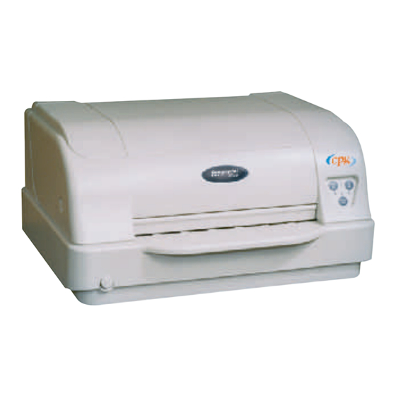
CPG Compuprint SP 40 Passbook Printer Manuals
Manuals and User Guides for CPG Compuprint SP 40 Passbook Printer. We have
1
CPG Compuprint SP 40 Passbook Printer manual available for free PDF download: Maintenance Manual
CPG Compuprint SP 40 Maintenance Manual (144 pages)
Brand:
CPG
| Category:
Printer
| Size: 4 MB
Table of Contents
Table of Contents
3
Preface
11
Fcc Regulations
12
Chapter 1 General Information
13
Main Features
13
Overview
13
Scope of the Product
13
Printer Parts
14
Product Structure
16
Mechanism and Electromechanical Devices
16
Electronics
17
Table 1.1 Printer Specification Summary
20
Technical Specifications
20
Maintaining Parameters
22
Chapter 2 Removals
23
Overview
23
Covers
24
Top Cover
24
Main Cover
24
Print Head
26
Mechanical Assy
28
Electronic Boards
29
Optional (LAN or USB) and Backpanel Boards
29
Engine Board
29
Controller Board
30
Power Supply Assy
30
Operator Panel
33
Motors Assy
34
Carriage Motor Assy
34
Carriage Pulley
34
Selector Motor Assy
36
Paper Motor Assy
36
Home Sensor Assy
38
Ribbon Sensor Assy
39
Ribbon Drive Assy
40
Carriage Assy
42
Mylar Bar Assy
44
Rear Roller Assy
46
Front Roller Assy
48
Maintenance Manual SP
50
Selector Cam
50
Lower Roller Assy (Rear Side)
52
Lower Roller Assy (Front Side)
53
Sensor Board and Sensor Cable
54
Platen Assy
56
Print Head Cables
58
Chapter 3 Operability and Configuration
59
Operability
59
Operator Panel
59
Function Keys
60
Leds
60
Table 3.1 O.P. Keys Meaning
60
Table 3.2 O.P. Leds Meaning
60
Overview
59
Printer Set-Up Mode by Operator Panel
61
Print of Self Test Page
62
Printer Configuration
63
Print of the Setup Forms
63
Filling in the Printer Setup Forms
64
Reading the Preprinted Forms
64
Setup Forms and Parameters
65
Table 3.3 Configuration Form Parameters Description
66
Table 3.4 Program 1 (Program 2) Form Parameters Description
69
Offset Adjustments
71
Printer Set-Up Mode by Web Browser (NIC Card)
73
Printer Set-Up Mode through the Application Sp40Setup (Via Serial I/F)
78
Entering the Printer Setup Mode
78
Install the Sp40Setup Application
78
Fig. 3.12A Initial Mask for Sp40Setup Installation
78
Fig. 3.12B Other Mask for Sp40Setup Installation
78
Fig. 3.12C Other Mask for Sp40Setup Installation
79
Fig. 3.12D Other Mask for Sp40Setup Installation
79
Fig. 3.12E Other Mask for Sp40Setup Installation
79
Run the Sp40Setup Application
80
Fig. 3.12F Other Mask for Sp40Setup Installation
80
Fig. 3.12G Other Mask for Sp40Setup Installation
80
Fig. 3.13 Initial Mask for Sp40Setup Application
80
Fig. 3.14A Read NVM Mask of the Sp40Setup Application
81
Fig. 3.14B Read NVM Mask of the Sp40Setup Application
81
Fig. 3.15 Write NVM Mask of the Sp40Setup Application
82
How to Download to SP40 an Existing Configuration File
83
Print of NIC Configuration Page
84
Fig. 3.16 Button to Print NIC Configuration
84
Fig. 3.17 Network Interface Configuration
84
Chapter 4 Service Maintenance
85
Cleaning
85
Initial Inspection and Tools
85
Overview
85
Set-Up
85
Consumables
86
Lubrication
86
Paper Specifications
86
Software Update
87
Basic Software Update through Parallel or Serial Interface
87
NIC Software Update through Parallel or Serial Interface
88
LAN Parameters Setup through Parallel Interface
89
Software Update through LAN Interface
90
Software Update through LAN Using FTP
90
Troubleshooting
91
Hexadecimal Dump
91
Printer Errors
91
Recoverable Errors
91
Unrecoverable Errors
92
Table 4.1 Not-Recoverable Leds Errors Code N
92
Troubleshooting Tables
94
Power Malfunction
94
Table 4.3 Power Malfunction Troubleshooting
94
Faulty Probability Guide
95
Table 4.4 Faulty Probability Guide
95
Reset the Consumable Parts
96
Chapter 5 Test & Diagnostic
97
General Rules for T&D Operations
97
Fig. 5.1 Operator Panel Sketch
97
How to Run T&D (with Standard Operator Panel)
97
Overview
97
Table 5.1 General Rules for T&D Operations
98
T&D USER Tests Description
99
Table 5.2 T&D USER Tests Description
99
Step by Step T&D Mode Flow Chart
100
Fig. 5.2 Schematic Flow-Chart of the T&D USER in Step by Step Mode
100
Step by Step T&D Mode Sequential Table
101
Table 5.3 Step by Step USER Complete Sequential Actions
101
T&D Errors Handling
106
Table 5.4 T&D Error Phase Sequential Actions
106
Led Meaning During T&D Error Condition
107
Table 5.5 Led Status for N° of Test in Error Condition
107
Table 5.6 Led Status for ORU in Error
108
Table 5.7 Led Status for Specific/Common Error Codes
109
T&D Errors Codes
110
Table 5.8 T&D Error Codes
110
Table 5.10 T&D Common Errors (Sensors) Codes
111
Table 5.11 T&D Common Errors (Mechanical) Codes
111
Table 5.9 T&D O.R.U. Codes
111
Requested Tools
112
Operator Panel with LCD
112
RS232 Serial Interface Loop-Back Connector
112
Fig. 5.3 Operator Panel with Display for T&D Activities
112
Fig. 5.4 Serial I/F Loop-Back
112
Parallel Interface Loop-Back Connector
113
Fig. 5.5 Parallel I/F Bi-Directional Loop-Back
113
Analysis of T&D Printouts
114
Printing Adjustment Printout (T&D 9)
114
Fig. 5.6 Pattern for Printout T&D9 of Standard Model (Reduced)
114
Standard Pattern Printout (T&D 10)
115
Fig. 5.7 Pattern for Printout T&D9+T&D10 of Standard Model (Reduced)
117
Monitor Though Serial Interface
118
Fig. 5.8 Remoter Mode Display (Hyper Terminal under W98)
118
Table 5.12 Serial Cable Connection for Remote T&D
118
Fig. 5.9 Remote Mode Display (Sensor 2 Error During T&D9)
119
Fig. 5.10 Remote Mode Display (Sensor 4 Error During T&D9)
120
Fig. 5.11 Remote Mode Display (Sensor 8 Error During T&D9)
120
Log File Printout (T&D 12)
121
Fig. 5.12 Example of T&D12 Log File (Without Errors)
122
Fig. 5.13 Example of T&D12 Log File (with Maximum N° of Errors)
122
Chapter 6 Paper Specifications
123
Overview
123
Single Sheet
124
Fig. 6.1 Single Sheet Dimensions
124
Table 6.1 Single Sheet Dimensions
124
Passbook
125
Table 6.2 Passbook Dimensions
125
Passbooks with Horizontal Fold
126
Passbooks with Vertical Fold
127
Table 6.4 Vertical Passbook Dimensions
127
Chapter 7 Electromechanical Devices
129
Overview
129
Print Head
129
Fig. 7.1 Print Head Architecture
129
Fig. 7.2 Print Head Connection (Rear View)
130
Table 7.1 Print Head Electrical Pin-Out
130
Fig. 7.3 Needles Position (Rear View)
131
Fig. 7.4A P.H. Operation
131
Fig. 7.4B P.H. Operation
131
Carriage Motor
132
Fig. 7.5 Carriage Motor Layout
132
Paper Motor
133
Fig. 7.6 Paper Motor Layout
133
Selector Motor
134
Fig. 7.7 Selector Motor Layout
134
Sensors
135
Fig. 7.10 Ribbon Sensor
135
Fig. 7.8 Home Position Sensor
135
Fig. 7.9 Edge Sensor
135
Fig. 7.11 Sensor Board and Optical Fibre
136
Table 7.2 Sensors Board Pin-Out
136
Chapter 8 Adjustments
137
Overview
137
Print Head Gap Adjustment
138
Mechanical Adjustments
139
Paper Belt Adjustment
140
Carriage Belt Adjustment
141
Selector Cam Adjustment
142
Advertisement
Advertisement
Related Products
CPG PageMaster 260N
CPG Categories
Ranges
Oven
Grill
Convection Oven
Fryer
More CPG Manuals
Login
Sign In
OR
Sign in with Facebook
Sign in with Google
Upload manual
Upload from disk
Upload from URL