
Related Manuals for RF Central RFX-RMR

Summary of Contents for RF Central RFX-RMR
- Page 1 RACK MOUNT RECEIVER (RFX-RMR) OPERATORS MANUAL Copyright 2005 RF Central RFX-RMR Issue 1.0 page 1 of...
-
Page 2: Table Of Contents
A1 and A2 audio demodulators .....................21 Analog demodulator Power supplies and monitoring ............22 Front Panel Controller / Display Board..................22 Mother Board ........................23 RFX-RMR - Power supplies and monitoring .................25 CONFIGURING THE RECEIVER ....................26 “Switches” and Key pad” control modes ................26 Status Monitoring ........................26 Top level Menu........................26... - Page 3 APPENDIX B - TABLE OF DVB-T NON-HIERARCHICAL BIT RATES........41 The information contained in this manual is the property of RF Central and may not be used, disclosed, or reproduced in any other form without the prior written permission of RF Central.
-
Page 4: General Safety Information
Avoid standing in front of high gain antennas (such as a dish) and never look into the open end of a waveguide or cable where RF power may be present. Users are strongly recommended to return any equipment that requires RF servicing to RF Central. WARNING- GaAs / BeO Hazard: Certain components inside the equipment contain Gallium Arsenide and Beryllium Oxide that are toxic substances. -
Page 5: Health & Safety
It is important to note that the guidelines adopted differ throughout the world and are from time-to-time re-issued with revised guidelines. For RF Central use, a maximum power density limit of 1w/m² is to be applied when calculating minimum safe working distances. -
Page 6: Maximum Rf Power Density Limits
/ frequency characteristics are presented in the two documents. To avoid complexity and to avoid areas of uncertainty, RF Central recommends the use of a single power density limit across the frequency range 100 kHz to 300 GHz. The 1w/m² power density limit we recommend satisfies the most stringent of the guidelines published to date. -
Page 7: Introduction
The analog section comprises an integral FM demodulator for one video channel with two associated audio channels. The RFX-RMR has a common RF input for both analog and digital receive modes, selection of mode is via the front panel control push button selection and LCD display. -
Page 8: Specifications
Receiver Noise Factor In the range 600-1500MHz IF Frequencies 70MHz Digital Receiver Specifications -92dBm to BER 10 (nom., QPSK) Receiver Threshold Compatible with all RF Central antennas Receive Antenna COFDM DVB-T 2k Demodulation QPSK, 16QAM, 64QAM Demodulation Modes FEC: Guard interval: 4.98 to 31.7 Mbit/s (automatic selection) - Page 9 7.0kg Weight Safe use: -20° to +50°C Environmental To spec: -10° to +45°C Altitude: 4500m Humidity: 95% long term Specifications may alter at the discretion of RF Central or to meet customer specific requirements. RFX-RMR Issue 1.0 page 9 of...
-
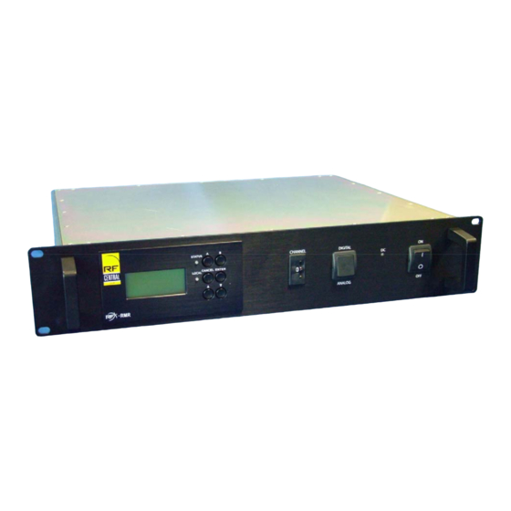
Page 10: Overview Of Rfx-Rmr Receiver
Front Panel 70MHz Module IF amp. The RFX-RMR comprises six main modules or assemblies:- Motherboard. This board accommodates the COFDM demodulator and MPEG digital decoder boards, as well as providing DC, signal, and I C communications routing to/from all other modules. - Page 11 Analog receiver module. This module accepts a feed of 70MHz from the Multi down- converter via a 70MHz amplifier/splitter mounted on the Motherboard. The module demodulates the video and 2 audios when the RFX-RMR is in analog receive mode. Front panel module. This module contains a microprocessor plus six push buttons and an LCD display for overall monitoring and control of the RFX-RMR.
-
Page 12: Front Panel Controls
Stable Green indicates that the RFX-RMR is functioning correctly. A flashing green light indicates that the RFX-RMR is functioning correctly but that no valid RF signal is present at the input to the receiver. A stable red light indicates that the unit has an alarm condition. -
Page 13: Rear Panel Connections
6 REAR PANEL CONNECTIONS Rear Panel view of RFX-RMR showing all connections RF I/P Connector Type: 50Ω ‘N’ type (female) Digital Receive Section - Video output (BNC connectors) Connectors for SDI/ASI digital (2), these connectors may be independently configured from the keypad to output either ASI or SDI. -
Page 14: Analog Receive Section Analog - Audio Outputs (Xlr Connectors)
Data Rx (-) Into Unit Not Used Not Used Ground Ground Not Used Data Tx (+) Out from Unit Not Used Data Rx (+) Into Unit Not Used Not Used Not Used Not Used RFX-RMR Issue 1.0 page 14 of... -
Page 15: Remote Monitoring And Control
Auxiliary functions, e.g. powering of a remote LNA and remote switching +12VDC Ground +12VDC Ground RL1 N.O RL1 COMMON RL1 N.C Ground RL2 N.O RL2 COMMON RL2 N.C Ground reserved Ground External AGC level meter 0 to +5VDC RFX-RMR Issue 1.0 page 15 of... -
Page 16: Circuit Descriptions
7 CIRCUIT DESCRIPTIONS RFX-RMR Simplified block diagram Composite Analogue receiver 70MHz Analogue audio 1 Analogue audio 2 70MHz monitor 630MHz COFDM RF input Multi Downconverter 4.57MHz Demodulator Downconverter MPEG decoder +12v 70MHz Mother board SDI or ASI video (1) +12v... -
Page 17: St Down-Converter
The output frequency of the first down-converter is 630MHz. Mixer BP filter 630MHz to 2 RF input Down-conv input Front panel display VCO/PLL RF frequency control RMR RX Down-converter RFX-RMR Issue 1.0 page 17 of... -
Page 18: In 1" Multi Down-Converter
A balanced form of the 4.57MHz IF is then passed to the COFDM demodulator board as detailed in section 7.3 The module contains a 20MHz reference oscillator to lock the two mixer local oscillators. There are no user serviceable parts on this module. Please contact RF Central Service Department for maintenance of this unit BP filter... -
Page 19: Cofdm Demodulator/Mpeg Decoder Board
The video, audio, and data outputs are routed via the motherboard to the rear panel of the receiver. The unit is controlled by the Front Panel display module. There are no user serviceable parts on this module. Please contact RF Central Service Department for maintenance of this unit RFX-RMR Issue 1.0... -
Page 20: Analog Demodulator - Technical Description
Composite video demod de-emphasis lamp switching Audio Subcarrier Analog audio 1 Modulator 1 Buffer Audio Subcarrier +5 v Modulator 2 Power +12 v supply -5 v RMR-D RX Analog receicer Simplified block diagram RFX-RMR Issue 1.0 page 20 of... -
Page 21: Introduction
8 INTRODUCTION The RFX-RMR X-0101 board provides the analog receiver function of the RMT digital / analog receiver system rack assembly. The board provides one (NTSC) video output and two audio outputs. Operation modes and audio sub carrier frequency selection is via front panel control. The R.F. input to the board, at 70MHz, is taken from the system common digital / analog IF / AGC circuit via a passive splitter network on the unit motherboard. -
Page 22: Analog Demodulator Power Supplies And Monitoring
This allows the ability to remove and change other boards within the unit without the loss of set-up parameters. At power-up this board initializes all the other boards and during normal operation monitors all the major functions and reports any problems as part of the unit status. RFX-RMR Issue 1.0 page 22 of... -
Page 23: Mother Board
The motherboard provides signal routing between the other modules and provides routing between:- Rear panel connectors Front panel push buttons and controller down converter and VCO Multi-down converter Demodulator/decoder DC PSU supplies to other units RFX-RMR Issue 1.0 page 23 of... - Page 24 11 to 18 VDC down converter -12 VDC Multi down-converter Aux. supply Analogue RX Digital RX Micro- controller RL 1 RL 2 down control AGC volts Analog RX control & Mon. Mother board Simplified block diagram RFX-RMR Issue 1.0 page 24 of...
-
Page 25: Rfx-Rmr - Power Supplies And Monitoring
RFX-RMR - Power supplies and monitoring The RFX-RMR power supply is mounted on the under-side of the Mother Board. See photograph in section 8.6 The +12v input supply is filtered and regulated by IC7, +5v linear regulator. This provides the +5 volt supply to the Receiver board circuits and is also the reference voltage for the discrete ‘low drop out’... -
Page 26: Configuring The Receiver
9.5.1 Status Monitoring The red/green ‘status’ LED on the front panel indicates the condition of the RFX-RMR, if a fault or warning exists the LED will indicate Red and the Status menu will indicate the nature of the fault / warning. -
Page 27: Top Level And Current Operational State
9.3.2 Top level and Current Operational State This is the display screen during normal operation of the RFX-RMR and indicates the Rx frequency (Channel number or Manual frequency), the current operating mode (analog or digital), and the receiver input level (dBm), (and CSI parameter - digital operation). The B button is used to scroll to... -
Page 28: Engineering Menu - Digital Receiving Mode
10 seconds, and then selecting the ‘Enter’ button. 9.5.1 “Switches and Key-pad” Control Mode The RFX-RMR may be configured such that the selection of channel frequency and operating mode (analog or digital) is selected from the keypad menu or via the two front-panel rocker switches. -
Page 29: Sdi / Asi Output Configuration
(as mentioned in clause 6.10). These may be used to control external equipment. The operation of the two relays is controlled through this menu. 9.5.10 LCD Timeout This function Enables or Disables the automatic switching off of the LCD backlight function. RFX-RMR Issue 1.0 page 29 of... -
Page 30: Audio Offset
9.5.11 Audio offset The analog audio outputs from RFX-RMR Receiver are designed to feed into a 600Ω input impedance. If the receiver is connected to a higher impedance load, the output level will be ~6dB high. This can be compensated for by using the ‘audio offset’ function. -
Page 31: Channel Plan
LCD Timeout The menu used is the same as the digital menu as mentioned in clause 9.5.10 9.7.8 Prog Channels The menu used is the same as the digital menu as mentioned in clause 9.5.12 RFX-RMR Issue 1.0 page 31 of... - Page 32 “A” = cursor left button “B” = cursor right Select Set Level -1.5 dB Manual 2345.00MHz RMR RX MENU Only available in keypad mode RMR MENU (1) (Operations menu – digital RX mode) RFX-RMR Issue 1.0 page 32 of...
- Page 33 Aux supply RRMB-0101-01 RDMI-0102-01 Key pad CVBS 3410AYY02-01 Select Select Select Select Select Aux supply Control Mode CHANNEL PLAN Switches NTSC Select BYTE RMR RX MENU RMR MENU (2) (Engineering menu – digital RX mode) RFX-RMR Issue 1.0 page 33 of...
- Page 34 ANALOG RX Select Manual 2446.00MHz button “A” = cursor left button “B” = cursor right Select Manual 2345.00MHz Only available in keypad mode RMR RX MENU (Operations menu – Analog RX mode) RMR MENU (3) RFX-RMR Issue 1.0 page 34 of...
- Page 35 “A” = cursor left Black lvl clamp Aux supply Relay 1 Relay 2 Control Mode CHANNEL PLAN button “B” = cursor right Switches RMR RX MENU (Engineering menu – Analog RX mode) RMR MENU (4) RFX-RMR Issue 1.0 page 35 of...
- Page 36 “A” = cursor left Control Mode CHANNEL PLAN Black lvl clamp Aux supply Relay 1 Relay 2 button “B” = cursor right Switches RMR RX MENU (Engineering menu – Analog RX mode) RMR MENU (4) RFX-RMR Issue 1.0 page 36 of...
-
Page 37: Preparing For Operation
10.1 The RFX-RMR Receiver 10.1.1 Antennas The RFX-RMR can be used with a variety of RF Central antennas RFX-OMNI antennas are typically used for ground based mobile operations, or helicopter air to ground GPS controlled antenna for helicopter air to ground... -
Page 38: The Transmitting Equipment
10.2 The Transmitting Equipment The RFX-RMR may be used with a variety of RF Central analog and digital transmitters including: RMT, digital/analog transmitter CMT Clip-On transmitter Full details of the operation of the transmitters is given in the associated manual Check that audio, video, and DC cables of sufficient total length and are in good condition. -
Page 39: System Remote Monitoring And Setup
11 SYSTEM REMOTE MONITORING AND SETUP Using a PC running Hyper Terminal or other terminal emulator, the RFX-RMR can be configured without the use of the operator controls and LCD display. The current configuration can also be obtained via this RS232/RS485 interface. The RMR is also remote controllable via other commercially available control systems. -
Page 40: Appendix A - Mpeg Encoder Parameter Sets
6.032086 QPSK, MP@ML, 4.75 0010-00 1/2, 1/32 GOP4 Note: The above parameters are typical for the RFX-RMR and are issued for guidance only. Some Receivers may have different configurations according to individual customer requirements. RFX-RMR Issue 1.0 page 40 of... -
Page 41: Appendix B - Table Of Dvb-T Non-Hierarchical Bit Rates
17.6 16.6 14.9 20.1 19.5 18.4 16.6 21.1 20.5 19.4 17.4 64-QAM 1/32 1/16 18.1 17.6 16.6 14.9 24.1 23.4 22.1 19.9 27.1 26.3 24.9 22.4 30.2 29.3 27.6 24.9 31.7 30.7 29.0 26.1 RFX-RMR Issue 1.0 page 41 of...
Need help?
Do you have a question about the RFX-RMR and is the answer not in the manual?
Questions and answers