
Related Manuals for RF Central MICROLITE

Summary of Contents for RF Central MICROLITE
- Page 1 MICRO ECEIVER HD/SD COFDM Dual Diversity Receiver User Manual IMT PUBLICATION: M23-0005-00A, REV 1.1...
-
Page 2: Microlite Receiver
MicroLite Receiver User Manual Revision History Date Revision Modified by Description May 16, 2011- Dave Anderson 0.0D Initial Writing June 13, 2011 (Mike Hardy) August 8th. 2011 0.1D Mike Hardy Ongoing updates and clarifications October 12, 2011 0.2D (BETA) Mike Hardy... - Page 3 MicroLite Receiver User Manual make every effort to ensure our documentation is as accurate and as complete as possible. In the event that you find any errors or omissions, please contact Customer Tech Support at (908) 852-3700, or via email at service@nucomm.com.
-
Page 4: Table Of Contents
Manual Overview _________________________________________________________________ 7 Description ____________________________________________________________ 9 MICRO microLite Features and Benefits _____________________________________________________ 9 Frequency Bands ________________________________________________________________ 11 microLite Receiver Theory of Operation ______________________________________________ 11 2.3.1 Dual Antenna Inputs _____________________________________________________________________ 12 2.3.2 Dual Microwave Receiver COFDM Demodulator Circuits ________________________________________ 12 2.3.3... - Page 5 RS232 Control and User Data ______________________________________________________________ 22 4.4.4 ASI Out _______________________________________________________________________________ 22 Connect Antennas _______________________________________________________________ 23 Operation ___________________________________________________________________ 25 Power up the MicroLite Receiver ___________________________________________________ 25 Pre-Configure the MLR user options _________________________________________________ 25 Control and LED Interface _________________________________________________________ 25 5.3.1 Buttons: _______________________________________________________________________________ 26 5.3.2...
- Page 6 MicroLite Receiver User Manual Chapter One Introduction Revision 1.1...
-
Page 7: Introduction
MicroLite Receiver User Manual 1 Introduction This document is a user manual for RF Central’s microLite Receiver [MLR]. The MLR is a compact, narrowband COFDM microware receiver that utilizes dual antenna diversity for robust, error free signal reception. The MLR is ideal for applications requiring a full featured high performance HD or SD receiver housed in a compact enclosure. - Page 8 MicroLite Receiver User Manual Chapter Two Description Revision 1.1...
-
Page 9: Micro Lite Description
Table 2-1 summarizes key features and benefits of the MLR. The microLite Receiver is a receiver that utilizes advanced silicon tuners and dual antenna inputs for robust, error free signal reception. The MLR can receive either HD or SD video transmissions using COFDM modulated microwave signals. -
Page 10: Table 2-1: Micro Lite Receiver - Summary Of Features And Benefits
MicroLite Receiver User Manual Table 2-1: M - Summary of Features and Benefits ICRO ECEIVER Feature Benefit COFDM facilitates high data rates and robust signal reception. COFDM HD and SD Receives both high definition and standard definition video Microwave Receiver transmissions. -
Page 11: Frequency Bands
MicroLite Receiver User Manual 2.2 Frequency Bands The microLite Receiver is available in the following bands: Table 2-2: MLR Frequency Bands Base Part Number Frequency (GHz) 21MLR 2.025-2110 23MLR 2.200-2.400 58MLR 5700-6000 2.3 microLite Receiver Theory of Operation Major blocks in the MLR diagram include:... -
Page 12: Dual Antenna Inputs
MicroLite Receiver User Manual Figure 2-1: Internal Block Diagram 2.3.1 Dual Antenna Inputs The MLR has two SMA antenna input connectors. The input impedance of the antenna connectors are 50 ohms. The frequency band supported by the antenna connectors are labeled next to the antenna inputs. -
Page 13: Mpeg4 Decoder
MicroLite Receiver User Manual 2.3.4 MPEG4 Decoder The MLR contains a built-in MPEG4 (H.264 part 10) compliant decoder. The decoder audio and video output is available on the SDI output jack. Both HD-SDI and SD-SDI are output on the SDI jack. -
Page 14: Remote Control Via Rs-232
MicroLite Receiver User Manual 2.4.2 Remote Control via RS-232 An RS-232 command set is implemented to allow remote control of all configuration options, as well as monitoring of internal status and settings. Commands and responses are sent via the RS-232 serial interface on the 9-pin connector. - Page 15 MicroLite Receiver User Manual Chapter Three Specifications Revision 1.1...
-
Page 16: Specifications
MicroLite Receiver User Manual 3 Specifications 3.1 Frequency Bands and RF Performance Base Part Number Frequency (GHz) 23MLR 2.025-2.500 58MLR 5.725-5.850 Tuning step size: 250 KHz Frequency stability: ± 10ppm 3.2 Modulation Modes Modes are auto detected within modulation format... -
Page 17: System
MicroLite Receiver User Manual 3.5 System ASI Output: Auto output rate follows modulation or fixed output user selectable (PCR Retime stamp) User Data: RS232 Side channel; 300-115K Baud Latency (*using MicroLite Transmitter): o 4 frames in Low Latency Mode for all... - Page 18 MicroLite Receiver User Manual Chapter Four Installation and Operation Revision 1.1...
-
Page 19: Installation
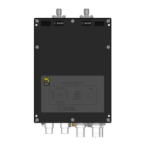
MicroLite Receiver User Manual Installation and Operation 4.1 Overview This chapter contains steps for installing the MicroLite Receiver in typical environments where it may be used. 4.2 Identifying MLR Physical Features and Interfaces 4-1: microLite Outline Drawing Revision 1.1... -
Page 20: Figure 4-1: Output Connectors
MicroLite Receiver User Manual Figure 4-2: Output Connectors Table 4-1: Output Connectors Item Description Connectors Left, Right Audio Line Outputs 75 Ohm RCA HD-SDI or SD-SDI Output Video Composite Video (PAL or NTSC) Encoded Video Output DC In Power Supply Input 2.5mm jack... -
Page 21: Physical Installation
MicroLite housing. Failure to comply will result in voiding of the warranty. ______________________________________________________________ 4.3 Physical Installation Remove microLite Receiver (MLR) from the case. The mounting bracket with MLR is preassembled. Attach MLR to the Magic Arm using tripod mount bracket. Connect Video output as needed (BNC connector). -
Page 22: Connect External Signals
MicroLite Receiver User Manual 4.4 Connect External Signals The microLite Receiver has the following major output interfaces: Power Interface RS-232 Serial Port Left and Right Audio Outputs Composite Video Output (not down converted from HD) ASI Video Output SDI Output for HD-SDI and SD-SDI Video User Data 4.4.1 Audio and Video... -
Page 23: Connect Antennas
MicroLite Receiver User Manual 4.5 Connect Antennas Connect antennas directly to the N RF input connectors, or via 50-Ohm cables. WARNING If cabling the MLR directly to a transmitter (e.g. for testing) you must use in-line RF attenuators. 50dB minimum recommended. - Page 24 MicroLite Receiver User Manual Chapter Five Operation Revision 1.1...
-
Page 25: Operation
MicroLite Receiver User Manual 5 Operation While this chapter contains basic information about the operation of the microLite Receiver, the programming of the unit (including preset configuration) via the NanoController GUI is not covered. Please refer to the NanoController manual (IMT Publication: M27-0001-00A) for detailed information on how to program and configure the unit. -
Page 26: Buttons
RSSI - LED’s will light to provide a Received Signal Strength Indicator. 5.4 Using the MLR to Receive Audio and Video The MLR receives and demodulates COFDM radio signals from the microLite Transmitter. It then decodes the MPEG4 transport stream for output. -
Page 27: Streaming Video Over Ip/Ethernet
MicroLite Receiver User Manual Use the Remote Control Interface and/or the Web GUI interface to verify the status of the MLR. Use a video monitor to view SD Composite video (NTSC or PAL, as appropriate). Display video on equipment with ASI or SDI input connectors. This may include video analysis equipment or PC’s with ASI or SDI input cards used for video storage and... - Page 28 MicroLite Receiver User Manual Proprietary Information and Disclaimer Notice All information and graphic images contained within this manual are the sole property of IMT, LLC, and are issued in the strictest of confidence. This material may not be reproduced, stored, copied, or converted in any form, nor shall it be disclosed to others or used for manufacturing or any other purpose without the written permission of authorized IMT personnel.
- Page 29 MicroLite Receiver User Manual Technical Support Information Technical Support personnel are available to extend technical assistance to customers while installing, operating, or troubleshooting IMT equipment. Please have your model number and serial number available. Telephone During IMT business hours, 8:30am - 5:30pm EST (-5 Hours, GMT), call: US ............
- Page 30 MicroLite Receiver User Manual IMT, LLC. 200 International Drive Mt. Olive, NJ, 07828, USA. T +1 908 852 3700 F +1 908 813 0399 www.imt-solutions.com Revision 1.1...
Need help?
Do you have a question about the MICROLITE and is the answer not in the manual?
Questions and answers