
Related Manuals for Balluff BCS M12K4 Series


Summary of Contents for Balluff BCS M12K4 Series
- Page 1 Kapazitive Näherungsschalter Capacitive Proximity Switches BCS M12K4… deutsch Betriebsanleitung english User’s guide...
- Page 2 www.balluff.com...
- Page 3 Kapazitive Näherungsschalter BCS M12K4… Betriebsanleitung deutsch...
- Page 4 www.balluff.com...
-
Page 5: Table Of Contents
Switch Point Mode 6.1.7 Device Temperature 6.1.8 Physical Output Delay 6.1.9 Physical Output Type Prozessdaten 6.2.1 Aufbau Eingangsdaten 6.2.2 Inhalte Eingangsdaten ISDU-Daten Systembefehle Ereignisse, Events Verfügbare Sensortypen und Zubehör Verfügbare Sensortypen Zubehör Technische Daten Typenschlüssel und Typenschild Typenschlüssel Typenschild www.balluff.com deutsch... -
Page 6: Benutzerhinweise
Der Lieferumfang beinhaltet folgende Teile: – Näherungsschalter – Befestigungsmuttern – Montageanleitung Im Interesse ständiger Produktverbesserungen können sich die technischen Daten des Pro- dukts und der Inhalt dieser Betriebsanleitung jederzeit ohne Ankündigung ändern. Den aktuellen Stand der Betriebsanleitung erhalten Sie im Internet unter www.balluff.com. deutsch... -
Page 7: Sicherheit
Betrieb zu nehmen und gegen unbefugte Benutzung zu sichern. Balluff haftet nicht für Schäden, die aus einer fehlerhaften Benutzung des Sensors resultieren. Ebenso übernimmt Beachten Sie die Unfallverhütungsvorschriften und örtlich Balluff keine Haftung, wenn der Sensor beschädigt wird. -
Page 8: Produktbeschreibung
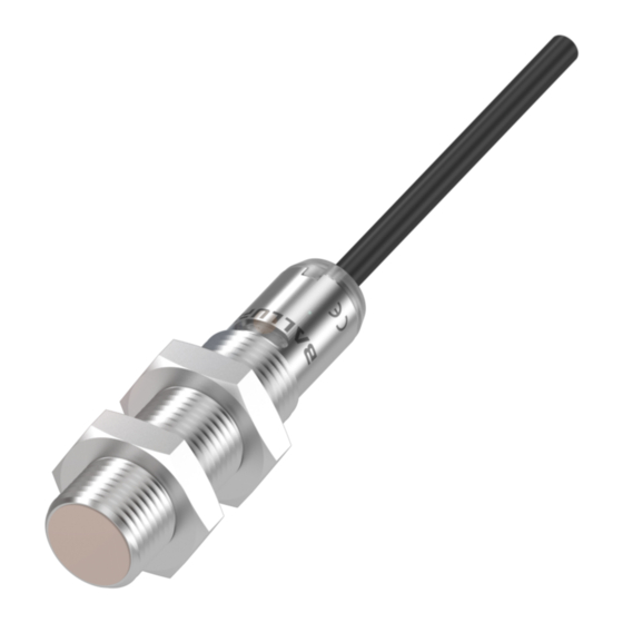
BCS M12K4… Kapazitive Näherungsschalter Produktbeschreibung Steckerausführung Sensoren der Serie BCS M12K4… arbeiten nach dem – bündig kapazitiven Messprinzip und können zur Objekterkennung oder Füllstandserfassung eingesetzt werden. Die Produktfamilie besteht aus folgenden zwei Sensorbau- formen: – bündige Sensoren (vorzugsweise zur Objekterkennung) – nicht bündige Sensoren (medienberührend, vorzugs- –... -
Page 9: Einbau Und Anschluss
Einbau Elektrischer Anschluss Anschlussbild IO-Link Umgebungsbedingungen im Datenblatt beach- ten! Das Datenblatt erhalten Sie im Internet unter www.balluff.com. Der Sensor kann in jeder beliebigen Lage eingebaut wer- den. Anschlussbild konventionell 4.1.1 Standardmontage mit Muttern Der Sensor kann mit M12-Muttern direkt in einer Bohrung montiert werden. -
Page 10: Betrieb
BCS M12K4… Kapazitive Näherungsschalter Betrieb LED-Anzeigen Bedienung Dieses Kapitel beschreibt die lokale bzw. Vor-Ort-Bedie- LED-Anzeigen im Normalbetrieb nung des Sensors. Für IO-Link-Sensoren sind weitere Die Sensorzustandsanzeige (grüne LED) leuchtet im Nor- Funktionen verfügbar. Diese sind im Kapitel IO-Link-Funkti- malbetrieb dauernd. Bei einem Fehler (z. B. Überlast am onen ab Seite 10 beschrieben. -
Page 11: Auf Werkseinstellung Zurücksetzen
Reiniger entfernt werden. Bild 5-2: Abgleich zur Füllstanderkennung, 1) Aktive Fläche, 2) Befe- stigungsgewinde M12x1, 3) Befestigungsmuttern, Eine Instandsetzung des Sensors ist nicht möglich. 4) Anzeige Sensorzustand (grüne LED), 5) Anzeige Schalt- zustand (gelbe LED), 6) Behälterwand, 7) Flüssigkeit Befolgen Sie die nationalen Vorschriften zur Entsorgung. www.balluff.com deutsch... -
Page 12: Io-Link-Funktionen
Die zur Konfiguration notwendigen Beschrei- Data Storage bungsdateien (IO-Link Device Description – Der Data-Storage-Mechanismus wird gesperrt, ein auto- IODD) sowie weitere Informationen zu IO-Link finden Sie unter www.balluff.com. matischer Parameterabgleich mit dem Master wird unter- drückt. Ohne IO-Link-Master arbeiten IO-Link-Sensoren im SIO- Local Parametrization... -
Page 13: Switch Point Mode
Aufbau Eingangsdaten Byte 1 Byte 0 PDV1 ‚0‘ ‚0‘ ‚0‘ BDC1 ← Send Direction 6.2.2 Inhalte Eingangsdaten Name Datentyp Bit-Offset Bit-Länge Wertebereich Beschreibung PDV1 UINT12 0…4095 Aktueller Sensorwert in Digits BDC1 Bool TRUE = Aktiv Schaltzustand FALSE = Inaktiv www.balluff.com deutsch... -
Page 14: Isdu-Daten
Teach Channel 0x000E PDInput Array[2] Beschreibung (14) Descriptor Prozessdaten Eingang OctetT3 0x010100 Schaltsignal OctetT3 0x020C04 Analogwert 0x0010 Vendor Name String „BALLUFF“ Hersteller Name (16) 0x0011 Vendor Text String „www.balluff.com“ Hersteller Text (17) 0x0012 Product String ≤ 32 Zeichen Typschlüssel, (18) Name typabhängig... - Page 15 = 0 – Mode UINT8 1 – Single Point Schaltpunkt Mode Betriebsart – Hysteresis UINT8 0…10, default = 5 Schaltpunkt Hysterese 0x0052 Device Array[3] 0…3 Temperaturen, (82) Temperature Werte in °C × 10 INT16 Actual INT16 Min. since Powerup INT16 Max. since Powerup www.balluff.com deutsch...
-
Page 16: Systembefehle
BCS M12K4… Kapazitive Näherungsschalter IO-Link-Funktionen (Fortsetzung) Index (dez) Name Datentyp Sub Index Zugriff Wertebereich Beschreibung 0x00B2 Physical Array[2] (178) Output Delay – On UINT8 0…5000 (default = 0) Verzögerung EIN (in ms) – Off UINT8 0…5000 (default = 0) Verzögerung AUS (in ms) 0x00B4 Physical UINT8 1 –... -
Page 17: Verfügbare Sensortypen Und Zubehör
M12-Zwischenstecker mit Teach-Taste (Teach-Adapter) BAM MC-XA-027-D12,0-1 BAM0218 Klemmhalter / Befestigungsschelle (Aluminium) BES 12,0-BS-1 BAM00C4 Klemmhalter / Befestigungsschelle (PA 6) BES 12-HW-1 BAM00C0 Montagewinkel (Aluminium) BES 12,0-KB-5-F BAM00CH Klemmhalter / Klemmbock (PC) Weitere Varianten und Anschlussleitungen finden Sie auf unserer Homepage. www.balluff.com deutsch... -
Page 18: Technische Daten
BCS M12K4… Kapazitive Näherungsschalter Technische Daten Nachstehende Daten gelten unter Vorbehalt. Maßgeblich ist das aktuelle Produktdatenblatt. Das aktuelle Produktdatenblatt erhalten Sie im Internet unter www.balluff.com. Elektrische Daten Betriebsspannung U Konventionell 12…30 V DC IO-Link 18…30 V DC Bemessungsbetriebsspannung U 24 V DC Stromaufnahme (Leerlauf) I bündige Bauform < 14 mA... -
Page 19: Typenschlüssel Und Typenschild
GO = PushPull Öffner PI = IO-Link Nenn-Schaltabstand: 50 = 5 mm 80 = 8 mm Bauform: C = bündig G = nicht bündig Anschluss: EP02 = 2 m Kabel, offenes Ende S04G = M12-Stecker Typenschild Bestellcode Seriennummer Produktionswoche und -Standort Zulassungen www.balluff.com deutsch... - Page 20 Balluff GmbH Schurwaldstrasse 9 73765 Neuhausen a.d.F. Phone +49 7158 173-370 Fax +49 7158 173-691 service@balluff.de...
- Page 21 Capacitive Proximity Switches BCS M12K4… User's Guide english...
- Page 22 www.balluff.com...
- Page 23 Physical Output Type Process data 6.2.1 Input data structure 6.2.2 Input data contents ISDU data System commands Events Available sensor types and accessories Available sensor types Accessories Technical Data Type code and part label Type code Part label www.balluff.com english...
-
Page 24: Notes To The User
Installation guide In the interest of continual product improvements the technical data for this product and the contents of this user's guide are subject to change without notice. The latest version of this manual can be found online at www.balluff.com. english... -
Page 25: Safety
Qualified personnel are those who can recognize the technical data is ensured only when using original possible hazards and institute the appropriate safety Balluff accessories. Use of any other components will void measures due to their professional training, knowledge, the warranty. -
Page 26: Product Description
BCS M12K4… Capacitive Proximity Switches Product description Connector type Series M12K4… sensors use a capacitive measuring – for flush mounting principle and can be used for object or level detection. The product family consists of the following two sensor styles: – Flush-mount sensors (preferably for object detection) –... -
Page 27: Installation And Connection
Electrical Connection IO-Link wiring diagram Observe the ambient conditions as specified in the data sheet! The data sheet can be found at www.balluff.com. The sensor can be installed in any position. 4.1.1 Standard installation using nuts Conventional wiring diagram The sensor can be installed directly in a hole using M12 nuts. -
Page 28: Operation
BCS M12K4… Capacitive Proximity Switches Operation LED indicators Operation This section describes local operation of the sensor. For LED displays in normal operation IO-Link sensors additional functions are available. These The sensor status indicator (green LED) is continuously on are described in section IO-Link functions starting in normal operation. -
Page 29: Reset To Factory Setting
Calibration for level detection, 1) Sensing surface, 2) Mounting thread M12x1, 3) Fastening nuts, 4) Sensor state Repairs to the sensor are not possible. indicator (green LED), 5) Switching state indicator (yellow LED), 6) Container wall, 7) Liquid Observe the national regulations for disposal. www.balluff.com english... -
Page 30: Io-Link Functions
You can find the description files (IO-Link Device Data storage Description – IODD) necessary for configuration as well as further information at www.balluff.com. The data storage mechanism is blocked and automatic parameter calibration with the master is inhibited. Without an IO-Link master, IO-Link devices operate in the... -
Page 31: Switch Point Mode
Byte 0 PDV1 BDC1 ← Send Direction 6.2.2 Input data contents Name Data type Bit offset Bit length Value range Description PDV1 UINT12 0…4095 Current sensor value in digits BDC1 Bool TRUE = active Switching state FALSE = inactive www.balluff.com english... -
Page 32: Isdu Data
PDInput Array[2] Process data input (14) Descriptor description OctetT3 0x010100 Switching signal OctetT3 0x020C04 Analog value 0x0010 Vendor Name String "BALLUFF“ Manufacturer name (16) 0x0011 Vendor text String "www.balluff.com“ Manufacturer text (17) 0x0012 Product String ≤ 32 characters Type code, depending... - Page 33 UINT8 1 – Single Point Operating mode Mode switching point – Hysteresis UINT8 0…10, default = 5 Hysteresis switching point 0x0052 Device Array[3] 0…3 Temperatures, (82) Temperature values in °C × 10 INT16 Actual INT16 Min. since Powerup INT16 Max. since Powerup www.balluff.com english...
-
Page 34: System Commands
BCS M12K4… Capacitive Proximity Switches IO-Link Functions (continued) Index (dec.) Name Data type Subindex Access Value range Description 0x00B2 Physical Array[2] (178) Output Delay – on UINT8 0…5000 (default = 0) Delay ON (in ms) – off UINT8 0…5000 (default = 0) Delay OFF (in ms) 0x00B4 Physical UINT8... -
Page 35: Available Sensor Types And Accessories
Clamping holder / mounting cuff (aluminum) BES 12,0-BS-1 BAM00C4 Clamping holder / mounting cuff (PA 6) BES 12-HW-1 BAM00C0 Mounting bracket (aluminum) BES 12.0-KB-5-F BAM00CH Clamping holder, clamp (PC) Other variants and single-ended cordsets can be found on our homepage. www.balluff.com english... -
Page 36: Technical Data
BCS M12K4… Capacitive Proximity Switches Technical Data The following data is provisional. The current product data sheet is definitive. The current data sheet can be found at www.balluff.com. Electrical Data Operating voltage U Conventional 12…30 V DC IO-Link 18…30 V DC Rated operating voltage U 24 V DC... -
Page 37: Type Code And Part Label
Rated switching distance: 50 = 5 mm 80 = 8 mm Construction: C = flush mount G = non-flush mount Connection: EP02 = 2 m cable, pigtail S04G = M12 connector Part label Order code Serial number Production week and location Approvals www.balluff.com english... - Page 38 Balluff GmbH Schurwaldstrasse 9 73765 Neuhausen a.d.F. Phone +49 7158 173-370 Fax +49 7158 173-691 service@balluff.de...
- Page 40 US Service Center CN Service Center Germany Germany China Balluff GmbH Balluff GmbH Balluff Inc. Balluff (Shanghai) trading Co., ltd. Schurwaldstrasse 9 Schurwaldstrasse 9 8125 Holton Drive Room 1006, Pujian Rd. 145. 73765 Neuhausen a.d.F. 73765 Neuhausen a.d.F. Florence, KY 41042 Shanghai, 200127, P.R.
Need help?
Do you have a question about the BCS M12K4 Series and is the answer not in the manual?
Questions and answers