Sign In
Upload
Manuals
Brands
Vishay Manuals
Accessories
VT 220
Vishay VT 220 Manuals
Manuals and User Guides for Vishay VT 220. We have
1
Vishay VT 220 manual available for free PDF download: Technical Manual
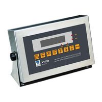
Vishay VT 220 Technical Manual (84 pages)
AND Protocol
Brand:
Vishay
| Category:
Accessories
| Size: 0 MB
Table of Contents
Table of Contents
2
Table of Figures
6
Legal Notice
7
Warranty
8
Safety Instructions
9
Declaration of Conformity
11
About this Document
12
1 Technical Specifications
14
General
14
Analog Input
15
Analog Output (Optional)
15
Digital Input
16
Digital Outputs
16
2 Installation
17
Site Requirements
17
Mounting the Indicator
17
Desktop Model (Aluminum Enclosure)
17
Figure 1 - Desktop Model, Front and Rear View
17
Wall-Mount Model (Stainless Steel Enclosure)
18
Figure 2 - Wall-Mount Model, Front and Rear View
18
Connecting Load Cells
19
Desktop Model (Aluminum Enclosure)
19
Figure 3 - Load Cell Connection Diagram for Wall-Mount Model
19
Wall-Mount Model (Stainless Steel)
20
Load Cell Operating Parameters
20
Figure 4 - Load Cell Connection Diagram for Stainless-Steel Model
20
Serial Connections
21
Printer and PC Cables
21
RS485 Cable Connections
21
Figure 5 - Printer and Pc Cables Connection Diagram
21
Connecting Power
22
Figure 6 - Rs485 Cable Connection Diagram
22
3 Display, Keys and Menus
23
The Display
23
Status Annunciators
24
Common Messages Shown on the Display
24
Front Panel Keys
25
Using Keys to Perform Operations
25
Using Keys to Navigate and Enter Information
26
Editing Multiple Digits
26
The Function Menu
26
Using the Function Menu
27
Function Summary
27
Setup Menus
31
Accessing and Navigating Setup Menus
31
Menu Structure
32
Parameter Summary
32
SETUP > SETUP 1 (General Operating Parameters)
32
SETUP > SETUP 2 (Com 1 Settings)
33
SETUP > SETUP 3 (Com 2 Settings)
34
SETUP > SETUP 4 (Tilt Switch)
35
SETUP > SETUP 5 (Setpoints)
35
SETUP > SETUP 6 (Lock Keys)
36
ACAL (Analog Output)
37
4 Calibration
38
Calibration with Standard Weights (S-Cal)
38
Zero (Dead-Load) Calibration
38
Span Calibration
39
Electronic Calibration (E-Cal)
39
Calculating Calibration Values
40
Setting Zero Calibration (Dead-Load) Value
40
Span (Max. Capacity) Calibration
41
Storing Calibration Data
41
Locking and Unlocking Calibration
41
Sealing Indicator Enclosure with Stickers
42
Figure 7 - Non-Removable Sticker
42
Figure 8 - Lead Wire Seal / Hard Plastic Sticker
42
Figure 9 - Wall Mount Model, Sealing Instructions
42
Figure 10 - D
43
Securing Load Receptor
44
Checking Seal Status and Audit Trail Counter
44
Figure 11 - D
44
5 General System Parameters
45
Par Menu
45
Accessing the Menu and Editing Parameters
45
PAR Menu Parameters
46
Dual-Scale Connecting and Parameter Settings
47
SETUP 1 (Inside SETUP Menu)
47
Accessing the Menu and Editing Parameters
47
SETUP 1 Parameters
48
6 Serial Communication
49
Serial Ports Configuration
49
RS232 Serial Port
49
RS485 Serial Port
49
Setting Port Output Parameters
50
Setting Port 1 Output
50
Setting Port 2 Output
50
Output Types
50
Local Printer
50
Continuous Weight Output
50
Continuous Weight Data Block Composition LEO Format
51
Continuous Weight Data Block Composition and Format
51
Two-Scale Operation
52
Continuous Weight with Tare
52
Data Block Composition
53
When Display Indication Is Not Weight
53
Print on Demand
53
Alibi Transmit
54
Alibi Mode Commands
54
Transmit Displayed Weight
54
Command "ZERO
54
Print on Demand Character
54
EDP Protocol Output
55
Full Protocol Workflow
55
Relevant Setup Parameters
55
EDP Data Block Composition
56
Remote Printer Output
56
Master-Slave Protocol Output
56
Master-Slave Commands
56
Doc # TM-VT200/220-EN
57
Gross-Tare-Net Weight Transmission
58
Tare Presetting Via PC
59
Separation of COM1 and COM2 Network Addresses
59
Standard Print Formats
60
Custom Print Formats
61
Creating a Custom Print Format
61
Downloading a Custom Print Format
62
Doc # TM-VT200/220-EN
63
7 Outputs and Digital Input
64
Specifications
64
Digital Outputs
64
Analog Outputs
64
Digital Input (Tilt Switch)
64
Connecting Digital Outputs and Tilt Switch
65
Setting Thresholds for Digital Setpoints
65
Figure 12 - D
65
Configuring Analog Output
66
Connecting PCB and Setting Jumper
67
Setting Analog Output Parameters
68
Calibrating D/A Converter
69
Using the Tilt Switch
70
Tilt Switch Options
70
8 Service Operations and Testing
71
Service Operations
71
Setting and Changing Calibration Password (Function 40)
71
Setting Date, Time and Serial Number (Function 05)
71
Displaying Remaining Battery Capacity (Function 02)
72
Checking Calibration Seal (Function 48)
72
Viewing Load Cell MV (Function 80)
72
Viewing A/D Count (Function 81)
73
View Software Version Number and Date (Function 82)
73
Locking and Unlocking Keys
73
Testing the Indicator
73
Testing ROM/RAM Integrity (Function 86)
73
Testing the Keypad and Display (Function 90, 91)
74
Testing Digital Input and Outputs (Function 93)
74
Testing the Print Buffer (Function 94)
75
Testing Data Received on both Serial Ports (Function 96)
75
9 Troubleshooting
76
Errors, Causes and Remedies
76
Checking Load Cell Connection
78
Checking Power Supply
78
Checking Digital Outputs
78
Appendix A: Technical Drawings
79
Contacting Vishay Transducers
84
Advertisement
Advertisement
Related Products
Vishay VT300
Vishay VT 200
Vishay VT400
Vishay JetWeigh-W
Vishay PM 1155
Vishay TSSP60 Series
Vishay TSSP6038
Vishay TSSP6038TT
Vishay TSSP6056
Vishay TSSP770 Series
Vishay Categories
Accessories
Receiver
Control Unit
Measuring Instruments
Security Sensors
More Vishay Manuals
Login
Sign In
OR
Sign in with Facebook
Sign in with Google
Upload manual
Upload from disk
Upload from URL