Table of Contents
Advertisement
Advertisement
Table of Contents

Related Manuals for Equinox Systems Hot Rod EQLED089


Summary of Contents for Equinox Systems Hot Rod EQLED089
- Page 1 Hot Rod User Manual Order code: EQLED089...
-
Page 2: Safety Advice
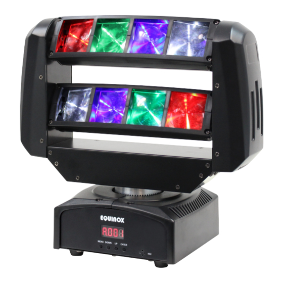
Safety advice WARNING FOR YOUR OWN SAFETY, PLEASE READ THIS USER MANUAL CAREFULLY BEFORE YOUR INITIAL START-UP! • Before your initial start-up, please make sure that there is no damage caused during transportation. • Should there be any damage, consult your dealer and do not use the equipment. • To maintain the equipment in good working condition and to ensure safe operation, it is necessary for the user to follow the safety instructions and warning notes written in this manual. • Please note that damages caused by user modifications to this equipment are not subject to warranty. CAUTION! CAUTION! TAKE CARE USING KEEP THIS EQUIPMENT THIS EQUIPMENT! AWAY FROM RAIN, HIGH VOLTAGE-RISK MOISTURE AND LIQUIDS OF ELECTRIC SHOCK!! IMPORTANT:... - Page 3 Product overview & technical specifications Hot Rod This compact moving head beam effect features 8 fast sweeping beams from its twin-tilting bars of eight 3W LEDs. The sweeping bars are fitted to a rotating base that fill the room with pin sharp coloured beams and look superb when used with fog or haze. The LEDs chase and pulsate across both of the fixture’s tilting bars ensuring a dynamic light show. • 8 x 3W CREE LEDs (R: 2, G: 2, B: 2, W: 2) • Beam angle: 3.4° • DMX channels: 1/11 or 15 selectable • Auto, sound active and master/slave modes plus built-in programs • Pan: 540°, Tilt: 205° • 0 - 100% dimming and variable strobe • Supplied with metal hanging bracket • 4 push button menu with LED display • IEC power input • 3-Pin XLR input/output • Fan cooled Specifications Power consumption Power supply 100~240V, 50/60Hz Fuse F3A 250V Dimensions 285 x 300 x 247mm Weight Order codes EQLED089 247mm 300mm www.prolight.co.uk Hot Rod User Manual...
-
Page 4: Technical Specifications
Technical specifications FUSE: F3A 250V www.prolight.co.uk MENU DOWN ENTER DMX INPUT DMX OUTPUT POWER INPUT: 100-240V~50/60Hz In the box: 1 x fixture, 1 x hanging bracket, 01 - LED display 04 - 3-Pin DMX input 1 x power cable, 02 - Function buttons 05 - 3-Pin DMX output 07 - Fuse F3A 250V & 1 x user manual 03 - Microphone 06 - IEC power input 08 - Fan www.prolight.co.uk Hot Rod User Manual... -
Page 5: Master/Slave Mode
Operating instructions Operating instructions A d d r DMX address setting 5 1 2 1 C h C h N d 1 1 C h Channel modes 1 5 C h N A s t S L N d S L 1 Master/slave mode S L 2 S h 1... -
Page 6: Dmx Channel Mode
Operating instructions DMX mode: Operating in a DMX control mode environment gives the user the greatest flexibility when it comes to customising or creating a show. In this mode you will be able to control each individual trait of the fixture and each fixture independently. To access the DMX address mode, press the “MENU” button and use the “UP” and “DOWN” buttons on Addr the rear of the unit to show on the LED display. Now press the “ENTER” button and use the “UP” and “DOWN” buttons to set the required DMX address. Press the “ENTER” button to confirm the setting. To exit out of any of the above options, press the “MENU” button. DMX channel mode: To access the DMX channel mode, press the “MENU” button and use the “UP” and “DOWN” buttons on ChNd the rear of the unit to show on the LED display. Now press the “ENTER” button and use the “UP” and “DOWN” buttons to choose one of the 1/11 or 15 DMX channel modes. Press the “ENTER” button to confirm the setting. To exit out of any of the above options, press the “MENU” button. 1 channel mode: 11 channel mode: Channel Value Function Channel Value Function 000-007 Blackout 000-255 Pan adjustment 0-540° 008-067 Show 1 (sensitivity low-high) 000-255 Tilt 1 adjustment 0-205°... - Page 7 Operating instructions 15 channel mode: Channel Value Function 000-255 Pan adjustment 0-540° 000-255 Tilt 1 adjustment 0-205° 000-255 Tilt 2 adjustment 0-205° 000-255 Pan/tilt speed 000-255 Master dimmer (0-100%) 000-007 LED off 008-015 LED on 016-131 Strobe (slow-fast) 132-139 LED on 140-181 Strobe ramp down 182-189 LED on 190-231 Strobe ramp up 232-239 LED on 240-247 Random strobe 248-255 LED on 000-255 Red 1 (0-100%) 000-255 Green 1 (0-100%) 000-255...
-
Page 8: Show Mode
Operating instructions Master/slave mode: To set the master unit, press the “MENU” button and use the “UP” and “DOWN” buttons on the rear SLNd of the unit to show on the LED display. Now press the “ENTER” button and use the “UP” and Nast “DOWN” buttons to choose . Press the “ENTER” button to confirm the setting. Then select your desired program. To set the other units in slave mode, press the “MENU” button and use the “UP” and “DOWN” buttons SLNd on the rear of the unit to show on the LED display. Now press the “ENTER” button and use the SL 1 SL 2 “UP” and “DOWN” buttons to choose either . Press the “ENTER” button to confirm the setting. The unit will now run in sequence with the master unit. To exit out of any of the above options, press the “MENU” button. Please ensure that all slave units are set to the same DMX channel mode as the master unit. Show mode: To access the show modes, press the “MENU” button and use the “UP” and “DOWN” buttons on the rear Shnd of the unit to show on the LED display. Now press the “ENTER” button and use the “UP” and Sh 1 Sh 4 “DOWN” buttons to choose between . Press the “ENTER” button to confirm the setting. To exit out of any of the above options, press the “MENU” button. Auto mode: To access the auto mode setting, press the “MENU” button and use the “UP” and “DOWN” buttons on Auto the rear of the unit to show... - Page 9 Operating instructions Pan invert setting: To access the pan invert setting, press the “MENU” button and use the “UP” and “DOWN” buttons on PInt the rear of the unit to show on the LED display. Now press the “ENTER” button and use the “UP” and “DOWN” buttons to choose between or . Press the “ENTER” button to confirm the setting. To exit out of any of the above options, press the “MENU” button. Tilt 1 invert setting: To access the tilt 1 invert setting, press the “MENU” button and use the “UP” and “DOWN” buttons on tIn1 the rear of the unit to show on the LED display. Now press the “ENTER” button and use the “UP” and “DOWN” buttons to choose between or . Press the “ENTER” button to confirm the setting. To exit out of any of the above options, press the “MENU” button. Tilt 2 invert setting: To access the tilt 2 invert setting, press the “MENU” button and use the “UP” and “DOWN” buttons on tIn1 the rear of the unit to show on the LED display. Now press the “ENTER” button and use the “UP” and “DOWN” buttons to choose between or . Press the “ENTER” button to confirm the setting. To exit out of any of the above options, press the “MENU” button. LED backlight: To access the LED backlight setting, press the “MENU” button and use the “UP” and “DOWN” buttons on the rear of the unit to show on the LED display. Now press the “ENTER” button and use the “UP”...
-
Page 10: Dmx Setup
DMX setup Setting the DMX address: The DMX mode enables the use of a universal DMX controller. Each fixture requires a “start address” from 1- 512. A fixture requiring one or more channels for control begins to read the data on the channel indicated by the start address. For example, a fixture that occupies or uses 7 channels of DMX and was addressed to start on DMX channel 100, would read data from channels: 100,101,102,103,104,105 and 106. Choose a start address so that the channels used do not overlap. E.g. the next unit in the chain starts at 107. DMX 512: DMX (Digital Multiplex) is a universal protocol used as a form of communication between intelligent fixtures and controllers. A DMX controller sends DMX data instructions form the controller to the fixture. DMX data is sent as serial data that travels from fixture to fixture via the DATA “IN” and DATA “OUT” XLR terminals located on all DMX fixtures (most controllers only have a data “out” terminal). DMX linking: DMX is a language allowing all makes and models of different manufactures to be linked together and operate from a single controller, as long as all fixtures and the controller are DMX compliant. To ensure proper DMX data transmission, when using several DMX fixtures try to use the shortest cable path possible. The order in which fixtures are connected in a DMX line does not influence the DMX addressing. For example; a fixture assigned to a DMX address of 1 may be placed anywhere in a DMX line, at the beginning, at the end, or anywhere in the middle. When a fixture is assigned a DMX address of 1, the DMX controller knows to send DATA assigned to address 1 to that unit, no matter where it is located in the DMX chain. DATA cable (DMX cable) requirements (for DMX operation): This fixture can be controlled via DMX-512 protocol. The DMX address is set on the back of the unit. Your unit and your DMX controller require a standard 3-pin XLR connector for data input/output, see image below. Further DMX cables can be purchased from all good sound and lighting suppliers or Pro Light Concepts dealers. -
Page 11: Line Termination
DMX setup Notice: Be sure to follow the diagrams below when making your own cables. Do not connect the cables shield conductor to the ground lug or allow the shield conductor to come in contact with the XLRs outer casing. Grounding the shield could cause a short circuit and erratic behaviour. Special note: Line termination: When longer runs of cable are used, Termination reduces signal transmission you may need to use a terminator on problems and interference. it is always advisable to connect a DMX terminal, the last unit to avoid erratic behaviour. (resistance 120 Ohm 1/4 W) between pin 2 Using a cable terminator will decrease (DMX-) and pin 3 (DMX+) of the last fixture. the possibilities of erratic behaviour. (3-pin - Order ref: CABL90, 5-pin - Order ref: CABL89) 5-pin XLR DMX connectors: Some manufactures use 5-pin XLR connectors for data transmission in place of 3-pin. 5-pin XLR fixtures may be implemented in a 3-pin XLR DMX line. When inserting standard 5-pin XLR connectors in to a 3-pin line a cable adaptor must be used. The diagram below details the correct cable conversion. -
Page 12: Weee Notice
WEEE notice Correct Disposal of this Product (Waste Electrical & Electronic Equipment) (Applicable in the European Union and other European countries with separate collection systems) This marking shown on the product or its literature, indicates that it should not be disposed of with other household wastes at the end of its working life. To prevent possible harm to the environment or human health from uncontrolled waste disposal, please separate this from other types of wastes and recycle it responsibly to promote the sustainable reuse of material resources. Household users should contact either the retailer where they purchased this product, or their local government office, for details of where and how they can take this item for environmentally safe recycling. Business users should contact their supplier and check the terms and conditions of the purchase contract. This product should not be mixed with other commercial wastes for disposal. www.prolight.co.uk Hot Rod User Manual...
Need help?
Do you have a question about the Hot Rod EQLED089 and is the answer not in the manual?
Questions and answers