Table of Contents
Advertisement
Quick Links
Advertisement
Table of Contents

Related Manuals for Equinox Systems EQLED019


Summary of Contents for Equinox Systems EQLED019
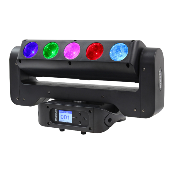
- Page 1 Switchblade User Manual Order code: EQLED019...
-
Page 2: Safety Advice
Safety advice WARNING FOR YOUR OWN SAFETY, PLEASE READ THIS USER MANUAL CAREFULLY BEFORE YOUR INITIAL START-UP! • Before your initial start-up, please make sure that there is no damage caused during transportation. • Should there be any damage, consult your dealer and do not use the equipment. •... - Page 3 Safety advice This fixture falls under Protection Class 1, therefore it has to be connected to a mains socket with a protective earthing connection. Risk group 2, RG-2: CAUTION! Do not stare at exposed LED in operation as it may damage/be harmful to the eyes.
- Page 4 16.6 • PowerCON input/output • 5-Pin XLR input/output 8° 160° • Fan cooled Specifications Switchblade Power consumption 365W Power supply 100~240V, 50/60Hz Fuse F5A 250V Dimensions 315 x 538 x 182mm Weight 11kg Order code EQLED019 www.prolight.co.uk Switchblade User Manual...
-
Page 5: Technical Specifications
Technical specifications 538mm 428mm 159mm 144mm 93mm 289mm www.prolight.co.uk Switchblade User Manual... - Page 6 Technical specifications In the box: 1 x fixture, 2 x omega clamps, 01 - LCD display 04 - 5-Pin DMX output 07 - Fuse F5A 250V 1 x power cable 02 - Function buttons 05 - PowerCON input 08 - Power switch &...
-
Page 7: Installation
Installation Before installing the fixture, the supporting structure (ie. truss) must be able to hold a minimum of 10 times the fixtures weight without any deformation (eg. 15kg - 150kg point load). The fixture must be secured with a secondary safety attachment when being installed (ie. an appropriate safety cable). Never stand directly below the fixture when mounting, removing, and/or servicing. - Page 8 Installation Installation: 1. Fasten each clamp to the omega clamps with a bolt and lock nut through the hole in the omega clamp. 2. Align and insert the omega clamp quick-lock fasteners with the respective holes on the bottom of the unit. 3.
- Page 9 Operating instructions Control Panel Menu: The LCD control panel situated on the front of the fixture allows the user to access the menu system adjust the fixtures settings. When the unit has been powered on the display will show “Equinox Switchblade”, “Motor Reset... Please Wait...”...
- Page 10 Operating instructions Main Menu - Defaults are in grey DMX address: Address To access the DMX address mode, press the “MENU” button and use the “UP” and “DOWN” Default buttons to show “DMX Address” on the LCD display. Now press the “ENTER” button and use the “UP”...
-
Page 11: Master/Slave Mode
Operating instructions Sound mode: Sound Mode To access the sound mode setting, press the “MENU” button and use the “UP” and “DOWN” buttons to show “Auto Mode” on the LCD display. Press the “ENTER” button and use the “UP” and “DOWN”... - Page 12 Operating instructions Factory Reset: Advanced Reset Settings Resets all the fixtures factory settings. To access the factory setting reset, press the “MENU” button and use the “UP” and “DOWN” buttons to show “Advanced Settings” on the LCD display. Press the “ENTER” button and use the “UP”...
-
Page 13: System Information
Operating instructions Operating instructions Display Invert: Display Invert To access the display invert setting, press the “MENU” button and use the “UP” and “DOWN” buttons to show “Advanced Settings” on the LCD display. Press the “ENTER” button and use the “UP” and “DOWN” buttons to show “Display Invert”. - Page 14 Operating instructions 2 channel mode: 15 channel mode: Channel Value Function Channel Value Function 000-007 No function 000-255 Pan adjustment 0-540° 008-022 Show 1 000-255 Pan fine adjustment 023-037 Show 2 000-255 Tilt adjustment 0-360° 038-052 Show 3 000-255 Tilt fine adjustment 053-067 Show 4 000-255...
- Page 15 Operating instructions 23 channel mode: Channel Value Function Channel Value Function 000-255 Pan adjustment 0-540° 000-007 No function 000-255 Pan fine adjustment 008-015 SMD blackout 000-255 Tilt adjustment 0-360° 016-131 SMD strobe (slow-fast) 000-255 Tilt fine adjustment 132-139 No function 000-255 Pan/tilt speed (fast-slow) SMD strobe ramp down...
- Page 16 Operating instructions 48 channel mode: Channel Value Function Channel Value Function 000-255 Pan adjustment 0-540° 000-007 No function 000-255 Pan fine adjustment 008-015 LED blackout 000-255 Tilt adjustment 0-360° 016-131 LED strobe (slow-fast) 000-255 Tilt fine adjustment 132-139 No function 000-255 Pan/tilt speed (fast-slow) LED strobe ramp down...
- Page 17 48 channel mode (cont.): Channel Value Function 000-007 No function 008-015 SMD blackout 016-131 SMD strobe (slow-fast) 132-139 No function SMD strobe ramp down 140-181 (slow-fast) CH45 182-189 No function SMD strobe ramp up 190-231 (slow-fast) 232-239 No function 240-247 SMD random strobe 248-255 No function...
-
Page 18: Dmx Setup
DMX setup Setting the DMX address: The DMX mode enables the use of a universal DMX controller. Each fixture requires a “start address” from 1- 512. A fixture requiring one or more channels for control begins to read the data on the channel indicated by the start address. -
Page 19: Line Termination
DMX setup Notice: Be sure to follow the diagrams below when making your own cables. Pin Configuration Do not connect the cables shield conductor to the ground lug or 3-Pin 5-Pin allow the shield conductor to come in contact with the XLRs Pin 1 - Ground outer casing. - Page 20 Multiple fixture power linking Power linking: This fixture provides power linking via the power output on the rear allowing multiple units to be connected together. The maximum number of fixtures that can be connected is 6 fixtures @ 240V or 3 fixtures @ 120V (including the first fixture). After the maximum number of fixtures are connected a new power run will need to be started.
-
Page 21: Weee Notice
WEEE notice Correct Disposal of this Product (Waste Electrical & Electronic Equipment) (Applicable in the European Union and other European countries with separate collection systems) This marking shown on the product or its literature, indicates that it should not be disposed with other household wastes at the end of its working life. - Page 22 www.prolight.co.uk Switchblade User Manual...
- Page 23 www.prolight.co.uk Switchblade User Manual...
- Page 24 www.prolight.co.uk Switchblade User Manual...
Need help?
Do you have a question about the EQLED019 and is the answer not in the manual?
Questions and answers