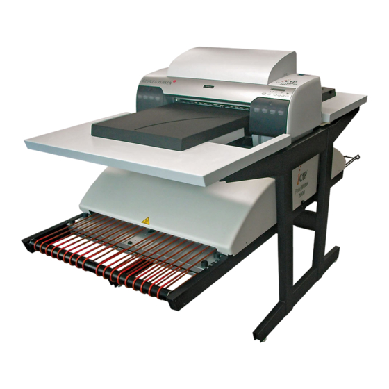
Glunz & Jensen PlateWriter 2000 Preinstallation Manual
Inkjet computer-to-plate system
Hide thumbs
Also See for PlateWriter 2000:
- Operating manual (102 pages) ,
- Manual (102 pages) ,
- Service manual (99 pages)
Table of Contents
Advertisement
Quick Links
Advertisement
Table of Contents

Subscribe to Our Youtube Channel
Related Manuals for Glunz & Jensen PlateWriter 2000


Summary of Contents for Glunz & Jensen PlateWriter 2000
- Page 1 Pre-installation Manual PlateWriter™ 2000...
- Page 3 Pre-installation Manual PlateWriter™ 2000 T11125 Edition AC, December 2011 This book has part No. 51591...
- Page 4 This manual is published by: GLUNZ & JENSEN A/S Selandia Park 1 DK-4100 Ringsted Denmark Phone:+45 57 68 81 81 E-mail: gjhq@glunz-jensen.com Internet: www.glunz-jensen.com © 2007 Glunz & Jensen A/S. All rights reserved. Pre-installation Manual - PlateWriter™ 2000 0746...
-
Page 5: Table Of Contents
Table of contents Table of contents Part 1: Introduction ........1-1 About this manual . -
Page 6: Table Of Contents
Table of contents Pre-installation Manual - PlateWriter™ 2000 0746... -
Page 7: Part 1: Introduction
Intended use of this manual This manual describes how to prepare the installation site for the installation of the • PlateWriter 2000 System. The procedures described in this manual require a reasonable level of technical skill and access to the proper tools. Reservations This manual was written and illustrated using the best possible information •... -
Page 8: Notes, Cautions, And Warnings
Introduction Important Notes, cautions, and warnings ! Throughout the manual notes, cautions, and warnings are written in bold like the example below: The cover can only be positioned on the finishing unit if the front cover is not " in place. Symbol Meaning Explanation... -
Page 9: Part 2: When The Crates Arrive
When the crates arrive Storing the crates Part 2: When the crates arrive Storing the crates The crates containing the PlateWriter System will usually arrive some time before the arrival of the Service Technician. In such a case you should prepare an appropriate place indoors to store the crates. -
Page 10: Transporting The Crates
When the crates arrive Transporting the crates Transporting the crates Handling the crates The icons on the crates indicate how to handle them during transport and storage: Ensure that the side Handle the Never expose the crate to indicated by the crate with care. -
Page 11: Part 3: Site Requirements
Site requirements General requirements Part 3: Site requirements General requirements Environmental requirements Provide a heating and ventilating system capable of maintaining room temperature between 20 and 24°C (68 and 75°F) and relative humidity between 40 and 80%. For heat emission see “Power consumption” on the page 3-6. Cleaning facilities We recommend that you have easy access to a sink and a water tap with hot water for cleaning purposes. -
Page 12: Space Requirements
Site requirements Space requirements Space requirements PlateWriter dimensions Side view 1182 mm (46.5”) 925 mm 920 mm (36.4”) (36”) 502 mm (19.7”) Top view 1942 mm (76.4”) 884 mm (34.8”) T31754 Pre-installation Manual - PlateWriter™ 2000 0746... -
Page 13: Free Space Around The Platewriter
Site requirements Space requirements Free space around the PlateWriter Decide where the unit shall be placed and make sure that the free space around it makes operation and servicing possible. Be aware of the following: Liquid Dot cartridges need to be replaced on each side of the unit. •... -
Page 14: Rip Workstation
Site requirements RIP workstation RIP workstation Location The RIP workstation must be placed within 3 m (9 ft) from the imaging unit as they need to be connected using the enclosed USB-cable. To avoid any harmful communication interference between the RIP workstation and the imaging unit, it is recommended not to use a USB-cable longer than 3 m (9 ft). -
Page 15: Power Supply
Site requirements Power supply Power supply Electrical installation must conform to local rules and regulations. Main power connection The PlateWriter System requires three main power connections, one for the PlateWriter itself, one for the finishing unit and ink dryer (the ink dryer is powered from the finishing unit), and one for the rip workstation. -
Page 16: Power Outlet Requirements
Site requirements Power supply Power outlet requirements If not already present, main power outlets should be installed in the room where the unit will be situated. Max. distance to the machine 2 m (6 ft.). The units are Class 1 appliances and must be connected to earthed mains socket outlets. -
Page 17: Power Cables
Site requirements Power supply Power cables " The equipment is delivered with the power cables required for the installation (USA only, outside USA these must be ordered separately). If, for some reason, you decide to use cables others than the supplied, make sure that they conform to the directions given below. - Page 18 Site requirements Power supply Finishing unit (USA) à à Equipment Power Outlet T11136 1. Appliance coupler 16A (IEC 60320) 2. Plug type NEMA L6-15P, 230V AC, 15A 3. Cable min. 3 x 18 AWG, type SJT or harder service Finishing unit (Rest of world) à...
-
Page 19: Part 4: Pre-Installation Checklist
Pre-installation checklist Part 4: Pre-installation checklist Please ask the customer to answer the following questions in order to ensure a trouble-free installation of the processor: 1. Delivery of the crate and transport to the installation site A. Is there a place indoors where the crates box can be stored temporarily? B. - Page 20 Pre-installation checklist 3. Ventilation and ink storage A. Is air condition/ventilation system capable of maintaining room temperature between 20 and 24°C (68 and 75°F) and relative humidity between 40 and 80%? B. Is capacity of air condition/ventilation adequate with regard to BTU as specified on page 3-6? C.
Need help?
Do you have a question about the PlateWriter 2000 and is the answer not in the manual?
Questions and answers