Neptronic TFL24 Specification & Installation Instructions
Efc
Hide thumbs
Also See for TFL24:
- Specification & installation instructions (2 pages) ,
- Specification and installation instructions (21 pages) ,
- Specification and installation instructions (24 pages)
Table of Contents
Advertisement
Quick Links
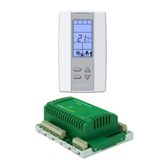
EFC Series fan coil controller
Technical Data
Electrical connection
Power supply
Power consumption
Setpoint range
Display resolution
Control accuracy
Proportional band
Operating temperature
Storage temperature
Relative humidity
Housing degree of protection
Weight
Interface
AM PM
. .
. .
MO TU WE TH FR SA SU
%RH
C
F
Dimensions
B
ºF / º C
TFL2x.doc/100910
Features:
•
Used to program/configure the EFC Fan Coil controller
•
Attractive modern look with large LCD and backlight
•
Icons driven information and 1 line of text information
•
3 wire or RJ45 Ethernet cable between thermostat & EFC
•
Programmable analog & digital outputs
•
Selectable fan speed contacts
•
Selectable Fahrenheit or Celsius scale
•
Occupancy sensor (programmable)
•
Multi level lockable access menu
•
Selectable internal or external temperature sensor
•
Programmable proportional control band & dead band
•
Change over by contact or external temperature sensor available
•
Anti-freeze protection
•
®
BACnet
MS/TP @ 9600, 19200, 38400, 76800bps
•
Selectable MAC Address by dip switch on the EFCB
•
Selectable device instance via technician menu
TFL24
3 wire cable
Temperature: ±0.5ºC [0.9ºF] @ 22ºC [71.6ºF] typical calibrated
The TFL2x can only work with the EFC. All the inputs/outputs are located on the EFC except for
Note
the temperature sensor built-in the TFL2x.
Display Symbols
Cooling ON
100% output
A: Automatic
Heating ON
100% output
A: Automatic
Fan ON
rd
3
A: Automatic
ºC: Celsius scale
ºF: Fahrenheit scale
or
Alarm
E
D
A
C
Specification & Installation Instructions
From EFC
1 VA
10ºC to 40ºC [50ºF to 104ºF]
±0.1ºC [0.2ºF]
0.5ºC to 5ºC [1ºF to 10ºF] adjustable
0ºC to 50ºC [32ºF to 122ºF]
-30ºC to 50ºC [-22ºF to 122ºF]
5 to 95 % non condensing
IP 30 (EN 60529)
120 g. [0.25 lb]
speed activated
Dimension
A
B
C
D
E
EFC Thermostat
TFL24
TFL25
TFL25
RJ45 (Ethernet cable)
Menu set-up Lock ON
Programming mode
(Technician setting)
Energy saving mode ON
Communication Status
Imperial (in)
Metric (mm)
2.85
73
4.85
123
1.00
24
2.36
60
3.27
83
1
Advertisement
Table of Contents

Subscribe to Our Youtube Channel
Related Manuals for Neptronic TFL24


Summary of Contents for Neptronic TFL24
- Page 1 EFC Thermostat Specification & Installation Instructions Features: TFL24 TFL25 • Used to program/configure the EFC Fan Coil controller • Attractive modern look with large LCD and backlight • Icons driven information and 1 line of text information • 3 wire or RJ45 Ethernet cable between thermostat & EFC •...
-
Page 2: Mounting Instructions
ON, Cooling only ON or Heating only ON) can be modified by end user. TFL24 – 3 wire cable (TB1 #1, 2 & 3) TFL25 – RJ45 Ethernet cable Connect TB1 #6 (A+) & #7 (B-) to EFCB for BACnet service port to work... -
Page 3: Programming Mode
TFL2x Specification & Installation Instructions Programming Mode When in this mode the symbol is displayed. Press on to advance to the next program function, press on button to return to the previous function and press on button to change values. You can exit the programming mode at any time; changed values will automatically be recorded. - Page 4 TFL2x Specification & Installation Instructions Step Display Description Values Set TO1 signal ramp: Display scrolls “SELECT TO1 SIGNAL RAMP” and shows the selected ramp. Select the desired ramp for TO1 from the options provided: OFF, COr, HEAt,COOL, rHt (reheat without fan), rHt (reheat with fan) Note: The symbol indicates that the fan outputs will be activated according to the demand.
- Page 5 TFL2x Specification & Installation Instructions Display Step Description Values Set TO2 signal ramp: Display scrolls “SELECT TO2 SIGNAL RAMP” and shows the selected ramp. Select the desired ramp for TO2 from the options provided: OFF, COr, HEAt,COOL, rHt (reheat without fan), rHt (reheat with fan) Note: The symbol indicates that the fan outputs will be activated according to the demand.
- Page 6 TFL2x Specification & Installation Instructions Display Step Description Values Set TO3 on-off closing level: (If “OnO ” was selected at step #19) Display scrolls “SELECT TO3 CLOSE PERCENT” and shows the value of the close position of the TO3 output. Range: 15 to 80 Select the percentage at which you want TO3 to close: x% of demand of the Increment: 1 %...
- Page 7 TFL2x Specification & Installation Instructions Step Display Description Values Minimum voltage of AO2 output: This menu will only be available if the signal ramp for AO2 is not set to OFF. Display scrolls “AO2 OUTPUT Min VDC” and shows the value of the minimum position Range: 0.0 to 10.0 Volt for the AO2 ramp.
- Page 8 TFL2x Specification & Installation Instructions Display Step Description Values Set DO2 digital output ramp: Display scrolls “SELECT DO2 SIGNAL RAMP” and shows the selected ramp. Select the desired ramp for on DO2 from the options provided: OFF, COr, HEAt, COOL, rHt (without fan) or rHt (with fan). Note: The symbol indicates that the fan outputs will be activated according to the demand.
- Page 9 TFL2x Specification & Installation Instructions Display Step Description Values Set DO3 closing level: Display scrolls “SELECT DO3 CLOSE PERCENT” and the value of the close position of the DO3 output. Range: 15 to 80% Increment: 1 % Select the percentage of the demand at which you want DO3 to close based on the demand of the selected ramp at step #36.
- Page 10 TFL2x Specification & Installation Instructions Display Step Description Values External temperature sensor calibration (AI1): This option is only available if the temperature sensor (step 44) is set to Out. Display scrolls “EXTERNAL TEMPER SENSOR OFFSET” and the temperature read by the Range: external temperature sensor (if connected).
- Page 11 TFL2x Specification & Installation Instructions Step Display Description Values Maximum occupancy override delay (DI3): Display scrolls “NO OCC DELAY OVERIDE MINUTES” and shows the selected delay value Range: 0 to 180 min Increment: 15 min (in minutes). Moon symbol is also displayed. Default value: 120 min Input the maximum delay available to the user.
- Page 12 TFL2x Specification & Installation Instructions Step Display Description Values Dead band for heating: Display scrolls “CONTROL DEAD BAND HEATING” and the value of the heating dead band, heating symbol is also displayed. Dead band range: 0.0 to 5.0ºC [0.6 to 10.0ºF] Select the desired value for the heating dead band.
- Page 13 TFL2x Specification & Installation Instructions Display Step Description Values Fan damping factor: Display scrolls “ADJUST DAMPING FACTOR SECONDS” and shows the selected delay value (in seconds). Range: 0 to 10 sec. symbol is also displayed. Increment: 1 sec. Select the damping factor for the fan. Default value: 0 sec.
-
Page 14: Operation Mode
Recycling at end of life ® ® At end of life, please return the thermostat to your Neptronic local distributor for recycling. If you need to find the nearest Neptronic authorized distributor, please consult www.neptronic.com. -
Page 15: Technical Data
EFC Fan Coil Controller Specification & Installation Instructions Features: E F C B 1 2 W Q 4 • Programmable analog & digital outputs _: No communication • Selectable fan speed contacts B: BACnet communication • 1: Plastic housing Selectable Fahrenheit or Celsius scale •... -
Page 16: Terminal Description
3- 24 Vac 4- 24 Vac Recycling at end of life ® ® At end of life, please return the thermostat to your Neptronic local distributor for recycling. If you need to find the nearest Neptronic authorized distributor, please consult www.neptronic.com.
Need help?
Do you have a question about the TFL24 and is the answer not in the manual?
Questions and answers