Table of Contents
Advertisement
Model
TRO24-EXT1
Extended Setpoint Range
Description
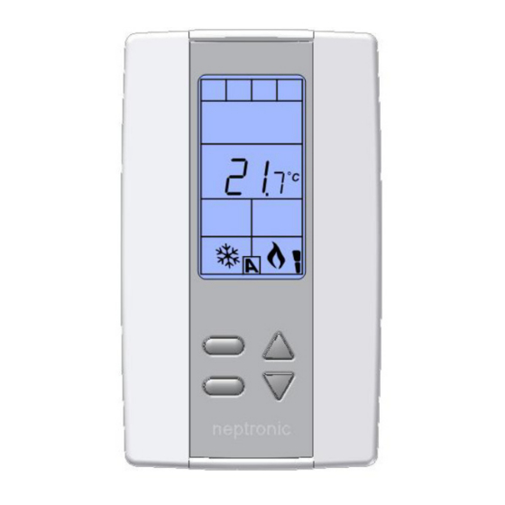
The TRO24-EXT1 is a combination controller and thermostat .
The VAV Thermostat Controller is designed for simple and
accurate control of any variable air volume box in a number of
zone control configurations. Its field configurable algorithms
enable versatile implementation of required control sequences.
Applications
•
Cooling only with or without terminal reheat
•
Heating/cooling with or without auto-changeover and
terminal reheat
•
Pressure dependent or pressure independent
•
Single duct or dual duct
•
Serial or parallel fan power boxes (on/off or ECM)
•
Supply and exhaust applications
•
Auxiliary heating sources, such as electric baseboards, can
also be applied
Features
•
Backlit LCD with simple icon and text driven menus
•
Configurable inputs and outputs
•
Precise temperature control with programmable PI function
•
Selectable Fahrenheit or Celsius scale
•
Extended setpoint range
•
Manual night set back override
•
Multi level lockable access menu and setpoint
•
Selectable internal or external temperature sensor (10 KΩ)
•
Changeover by contact or external temperature sensor
•
Pressure sensor input with air flow program
•
Selectable proportional control band and dead band
Technical Specifications
Description
Inputs
Outputs
Power supply
Power consumption
Setpoint range
External sensor range
Control accuracy
Proportional band
Electrical connection
Operating temperature
Storage temperature
Relative Humidity
Degree of protection of housing
Weight
TRO24-EXT1-Ext Setpnt-140922-ESA
Typical Application
VAV applications incorporate a central unit that delivers a
controlled volume of air, which can be cooled or heated, to
multiple zones. Each zone incorporates a VAV control box with
a motorized damper to adjust the flow of air to the controlled
zone based on the demand. Some configurations include one or
more of the following: air flow pressure sensor, fan, duct heater,
duct temperature sensor, and auxiliary heat (e.g. baseboard).
* Consult www.neptronic.com for details on these Neptronic products.
3 Universal analog inputs: 0-10Vdc, Thermistor (10k Type 3), or digital input (dry contact)
Available for sensors: external temperature, changeover, night set back or pressure
2 Analog outputs: 0-10Vdc or 2-10Vdc selectable (2mA max.)
4 TRIAC outputs: on/off, pulse 0 or 24Vac (250 mA max.), or 2 floating outputs
22 to 26Vac 50/60Hz
1VA
-30ºC to 90ºC [-22ºF to 194ºF] with external sensor
-40ºC to 100ºC [-40ºF to 212ºF]
Temperature: ±0.4ºC [0.8ºF]
0.5ºC to 5ºC [1ºF to 10ºF] adjustable
2
0.8 mm
[18 AWG] minimum
0ºC to 50ºC [32ºF to 122ºF]
-30ºC to 50ºC [-22ºF to 122ºF]
5 to 95% non condensing
IP 30 (EN 60529)
160 g. [0.36 lb]
VAV Thermostat Controller
Specification and Installation Instructions
TRO24-EXT1
TRO24-EXT1
Page | 1
Advertisement
Table of Contents

Subscribe to Our Youtube Channel
Related Manuals for Neptronic TRO24-EXT1


Summary of Contents for Neptronic TRO24-EXT1
-
Page 1: Typical Application
TRO24-EXT1 Extended Setpoint Range Description The TRO24-EXT1 is a combination controller and thermostat . The VAV Thermostat Controller is designed for simple and accurate control of any variable air volume box in a number of zone control configurations. Its field configurable algorithms enable versatile implementation of required control sequences. -
Page 2: Ds1 - Mode Selector
ºF / º C Wiring We strongly recommend that all Neptronic products be wired to a separate grounded transformer and that transformer shall service only Neptronic products. This precaution will prevent interference with, and/or possible damage to incompatible equipment. Terminal Description... -
Page 3: Mounting Instructions
Analog Output 1 Temperature Analog Output 2 Heating Analog Input 1 Cooling Analog Input 2 TRIAC Output 1 Analog Input 3 TRIAC Output 2 Air Flow TRIAC Output 3 Night Set Back TRIAC Output 4 Timer/Clock www.neptronic.com Page | 3... -
Page 4: Setpoint And User Control
Yes / No If you select Yes, the user can set the unit to “Off” via the Control Mode (see page 14). If you select No, the “Off” selection does not appear in the Control Mode. www.neptronic.com Page | 4... -
Page 5: Triac Output 1 (To1)
“Select TO2 Output Signal” Default: OnOf (on/off) Range: OnOf (on/off), PULs (pulsed) Select the desired signal from the available options. • If you select PULs, only the Heating 1 and Heating 2 ramps will be available at Step 14. www.neptronic.com Page | 5... -
Page 6: Triac Output 3 (To3)
This option appears only if you selected FLt (Floating) at Step 16. Set the desired value for floating time signal. “Select Motor Direct Reverse” Default: Dir (Direct) Range: Dir (Direct) or Rev (Reverse) Set the motor direction to either Direct (clockwise, 0 to 90°), or Reverse (counter clockwise, 90 to 0°). Go to Step 24. www.neptronic.com Page | 6... -
Page 7: Triac Output 4 (To4)
"Select AO1 Analog Ramp” Default: Cr1 (Cooling ramp 1) Range: Cr1, Cr2, Hr1, Hr2, COr, OFF Select the desired ramp from the available options. Cooling Ramp 1 Cooling Ramp 2 Heating Ramp 1 Heating Ramp 2 Changeover Ramp www.neptronic.com Page | 7... - Page 8 “Min Pos AO2 Output Percent” Default: Range: 0 to 100% Increment: This option does not appear if the signal ramp for AO2 is set to OFF (Step 25). Select the desired minimum position of the AO2 analog output. www.neptronic.com Page | 8...
-
Page 9: Analog Inputs (Ai1 To Ai3)
(AI1, AI2, or AI3), the display shows the temperature read by the external temperature sensor. Adjust the offset by comparing it with a known value (e.g. thermometer). If the sensor is not connected or short circuited, the display is blank “Error“. www.neptronic.com Page | 9... - Page 10 “Control Ramp 1 Heating” Default: 2.0ºC [4ºF] Range: 0.5 to 5.0ºC [1 to 10ºF] Increment: 0.5ºC [1ºF] Select the desired proportional band value of the heating ramp 1. The heating symbol is also displayed. www.neptronic.com Page | 10...
- Page 11 To protect the compressor, set the delay in minutes before activating or reactivating the cooling contact. “Adjust Intgral Time in Seconds” Default: 0 seconds Range: 0 to 250 seconds Increment: 5 seconds Set the desired value for the integration factor compensation. www.neptronic.com Page | 11...
-
Page 12: Air Flow Program Mode (Operation Mode)
• If Velocity Pressure Snesor (PrSa): Vnom =10.00V “Minimum Cooling Airflow” Default: Range: 0 to “maximum cooling airflow” Increment: Select the desired value of the minimum airflow in cooling. The minimum value is restricted by the maximum value (Step 59). www.neptronic.com Page | 12... - Page 13 If you can’t stabilize the system, you may need to increase the filter time value (Step 55). Return to Step 62. To exit the Air Flow Setup mode, set the Mode Selector DIP switch (DS1) must be set to "ON" position (Programming Mode). www.neptronic.com Page | 13...
-
Page 14: Operation Mode
This function is only available if you’ve set one of the analog inputs to either PrSd or PrSa (pressure sensor) in Step 32, 33 or 34 on page 9. Press and hold the key for 5 seconds to display the airflow value. www.neptronic.com Page | 14... - Page 15 VAV Thermostat Controller Specification and Installation Instructions Notes Recycling at end of life: please return this product to your Neptronic local distributor for recycling. If you need to find the nearest Neptronic authorized distributor, please consult www.neptronic.com. www.neptronic.com Page | 15...
- Page 16 400 Lebeau blvd, Montreal, Qc, H4N 1R6, Canada www.neptronic.com Toll free in North America: 1-800-361-2308 Tel.: (514) 333-1433 Fax: (514) 333-3163 Customer service fax: (514) 333-1091 Monday to Friday: 8:00am to 5:00pm (Eastern time)
Need help?
Do you have a question about the TRO24-EXT1 and is the answer not in the manual?
Questions and answers