Table of Contents
Advertisement
proform.com
Model No. PFTL13116.1
Serial No.
Write the serial number in the space
above for reference.
Serial Number
Decal
ACTIVATE YOUR
WARRANTY
To register your product and
activate your warranty today,
go to my.proform.com.
CUSTOMER CARE
For service at any time, go to
proformservice.com.
Or call 1-888-533-1333
Mon.–Fri. 6 a.m.–6 p.m. MT
Sat. 8 a.m.–12 p.m. MT
Please do not contact the store.
CAUTION
Read all precautions and instruc-
tions in this manual before using
this equipment. Save this manual
for future reference.
USER'S MANUAL
Advertisement
Table of Contents

Related Manuals for Pro-Form PRO 2000


Summary of Contents for Pro-Form PRO 2000
- Page 1 proform.com Model No. PFTL13116.1 Serial No. USER’S MANUAL Write the serial number in the space above for reference. Serial Number Decal ACTIVATE YOUR WARRANTY To register your product and activate your warranty today, go to my.proform.com. CUSTOMER CARE For service at any time, go to proformservice.com.
-
Page 2: Table Of Contents
TABLE OF CONTENTS WARNING DECAL PLACEMENT ............. . . 2 IMPORTANT PRECAUTIONS . -
Page 3: Important Precautions
IMPORTANT PRECAUTIONS WARNING: To reduce the risk of burns, fire, electric shock, or injury to persons, read all important precautions and instructions in this manual and all warnings on your treadmill before using your treadmill. ICON assumes no responsibility for personal injury or property damage sus- tained by or through the use of this product. - Page 4 19. Always stand on the foot rails when starting able to safely lift 45 lbs. (20 kg) to move the or stopping the walking belt. Always hold the treadmill. handrails while using the treadmill. 26. When folding or moving the treadmill, make 20.
- Page 5 STANDARD SERVICE PLANS...
-
Page 6: Before You Begin
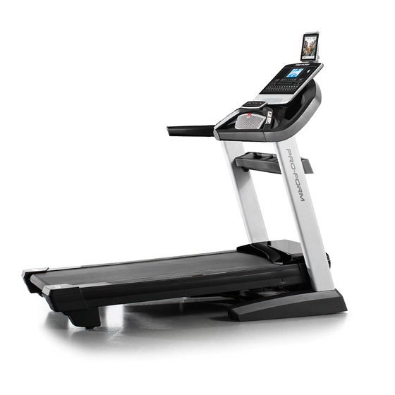
Thank you for selecting the revolutionary PROFORM ® reading this manual, please see the front cover of this PRO 2000 treadmill. The PRO 2000 treadmill offers an manual. To help us assist you, please note the product impressive selection of features designed to make your model number and serial number before contacting us. -
Page 7: Part Identification Chart
PART IDENTIFICATION CHART Use the drawings below to identify small parts used for assembly. The number in parentheses below each draw- ing is the key number of the part, from the PART LIST near the end of this manual. The number following the key number is the quantity used for assembly. -
Page 8: Assembly
ASSEMBLY • To hire an authorized service technician to • Left parts are marked “L” or “Left” and right parts assemble the treadmill, call 1-800-445-2480. are marked “R” or “Right.” • Assembly requires two persons. • To identify small parts, see page 7. •... - Page 9 2. Make sure that the power cord is unplugged. Remove the tie securing the Upright Wire (83) to the front of the Base (93). Next, identify the Right Upright (84). Have a sec- ond person hold the Right Upright near the Base (93).
-
Page 10: 93). Make Sure Not To Pinch The Upright Wire
4. Hold the Right Upright (84) against the Base (93). Make sure not to pinch the Upright Wire (83). Attach the Right Upright (84) with two 3/8" x 2 3/4" Screws (23), two 3/8" x 1 1/4" Screws (20), and four 3/8" Star Washers (25) as shown; do not fully tighten the Screws yet. - Page 11 6. Attach the two Handrails (74) to the Right and Left Uprights (84, 91) with the four 5/16" x 2" Screws (2) that you removed in step 5 and four 5/16" Star Washers (8); do not fully tighten the Screws yet. Be careful not to pinch the Upright Wire (83) on the right side.
- Page 12 8. See the inset drawing. Connect the Upright Wire (83) to the console wire (H). The connec- tors should slide together easily and snap into place. If they do not, turn one connector and try again. IF YOU DO NOT CONNECT THE CONNECTORS PROPERLY, THE CONSOLE MAY BECOME DAMAGED WHEN YOU TURN ON THE POWER.
- Page 13 10. IMPORTANT: To avoid damaging the Pulse Bar (80), do not use power tools, and do not overtighten the #10 x 3/4" Screws (6) or the 1/4" x 5/8" Screws (99). Tighten two 1/4" x 5/8" Screws (99) with two 1/4" Star Washers (77), and two #10 x 3/4"...
- Page 14 12. Attach the Left Handrail Bottom Cover (75) to the left Handrail (74) with two #8 x 3/4" Truss Head Screws (24); start both Truss Head Screws, and then tighten them. Be careful not to over- tighten the Truss Head Screws. Attach the Right Handrail Bottom Cover (82) to the right Handrail (74) as described above.
- Page 15 14. Carefully slide the Upright Crossbar (76) between the Right and Left Uprights (84, 91). Attach the Upright Crossbar with four 5/16" x 3/4" Screws (1); start all four Screws, and then tighten them. 15. Attach the Tray (97) to the Upright Crossbar (76) with four #8 x 3/4"...
- Page 16 16. Raise the Frame (52) to the upright position. IMPORTANT: Have a second person hold the Frame until step 18 is completed. Orient the Latch Crossbar (78) as shown. Make sure that the “This side toward belt” sticker (J) is facing the treadmill. Attach the Latch Crossbar (78) to the brackets (K) on the Frame (52) with the two 5/16"...
- Page 17 18. Remove the 5/16" Nut (9) and the 5/16" x 2 1/4" Bolt (4) from the bracket on the Latch Crossbar (78). Align the upper end of the Storage Latch (56) with the bracket on the Frame (52), and insert the 5/16"...
- Page 18 20. Attach the Tablet Holder (100) to the console assembly (G) with four M4 x 16mm Screws (3); start all four Screws, and then tighten them. Do not overtighten the Screws. 21. Make sure that all parts are properly tightened before you use the treadmill. If there are sheets of plastic on the treadmill decals, remove the plastic.
-
Page 19: The Chest Heart Rate Monitor
THE CHEST HEART RATE MONITOR HOW TO PUT ON THE HEART RATE MONITOR • Store the heart rate monitor in a warm, dry place. Do not store the heart rate monitor in a plastic bag or If the heart rate monitor looks like the one shown other container that may trap moisture. -
Page 20: How To Use The Treadmill
HOW TO USE THE TREADMILL HOW TO CONNECT THE POWER CORD more amps. To avoid overloading the circuit, do not plug other electrical devices, except for low- Use a Surge Suppressor power devices such as cell phone chargers, into the surge suppressor or into an outlet on the same Your treadmill, like other electronic equipment, can be circuit. - Page 21 CONSOLE DIAGRAM FEATURES OF THE CONSOLE To turn on the power, see page 22. To use the man- ual mode, see page 22. To use an onboard workout, The treadmill console offers a selection of features see page 24. To connect your tablet to the console, designed to make your workouts more effective and see page 26.
- Page 22 HOW TO TURN ON THE POWER HOW TO USE THE MANUAL MODE IMPORTANT: If the treadmill has been exposed to 1. Insert the key into the console. cold temperatures, allow it to warm to room tem- perature before you turn on the power. If you do See HOW TO TURN ON THE POWER at the left.
- Page 23 4. Change the incline of the treadmill as desired. The My Trail tab will show a track that represents 1/4 mile (400 m). As you exercise, the flashing To change the incline of the treadmill, press the rectangle will show your progress. The My Trail tab Incline increase or decrease button or one of the will also show the number of laps you complete.
- Page 24 6. Measure your heart rate if desired. 8. When you are finished exercising, remove the key from the console. Note: If you use the handgrip heart rate moni- When you are finished using the treadmill, step tor and the chest heart rate monitor at the same onto the foot rails, press the Stop button, then time, the console will not display your heart press the End/Summary button.
- Page 25 Each workout is divided into segments. One speed If the speed or incline setting is too high or too low setting and one incline setting are programmed for at any time during the workout, you can manu- each segment. Note: The same speed setting and/ ally override the setting by pressing the Speed or or incline setting may be programmed for consecu- Incline buttons;...
- Page 26 HOW TO CONNECT YOUR TABLET TO THE 5. Disconnect your tablet from the console if CONSOLE desired. The console supports BLUETOOTH connections to To disconnect your tablet from the console, first tablets via the iFit Bluetooth Tablet app and to compat- select the disconnect option in the iFit Bluetooth ible heart rate monitors.
- Page 27 THE SETTINGS MODE HOW TO USE THE SOUND SYSTEM The console features an information mode that keeps To play music or audio books through the console track of treadmill information and allows you to person- sound system while you exercise, plug a 3.5 mm male alize console settings.
-
Page 28: Fcc Information
FCC INFORMATION This console has been tested and found to comply with the limits for a Class B digital device, pursuant to part 15 of the FCC Rules. These limits are designed to provide reasonable protection against harmful interference in a residential installation. This equipment generates, uses, and can radiate radio frequency energy and, if not installed and used in accordance with the instructions, may cause harmful interference to radio communications. -
Page 29: How To Fold And Move The Treadmill
HOW TO FOLD AND MOVE THE TREADMILL HOW TO FOLD THE TREADMILL HOW TO MOVE THE TREADMILL To avoid damaging the treadmill, adjust the incline Before moving the treadmill, fold it as described at the to zero before you fold the treadmill. Then, remove left. -
Page 30: Maintenance And Troubleshooting
MAINTENANCE AND TROUBLESHOOTING MAINTENANCE b. After the power cord has been plugged in, make sure that the key is inserted into the console. Regular maintenance is important for optimal perfor- mance and to reduce wear. Inspect and properly tighten c. Check the power switch located on the treadmill all parts each time the treadmill is used. - Page 31 SYMPTOM: The incline of the treadmill does not c. Your treadmill features a walking belt coated with change correctly high-performance lubricant. IMPORTANT: Never apply silicone spray or other substances to a. Calibrate the incline system of the treadmill (see the walking belt or the walking platform unless THE SETTINGS MODE on page 27).
- Page 32 b. If the walking belt slips when walked on, fi rst SYMPTOM: The tablet holder does not stay in place remove the key and UNPLUG THE POWER CORD. Using the hex key, turn both idler roller a. Rotate the tablet holder backwards. Then, tighten screws clockwise, 1/4 of a turn.
-
Page 33: Exercise Guidelines
EXERCISE GUIDELINES Burning Fat—To burn fat effectively, you must exer- WARNING: cise at a low intensity level for a sustained period of Before beginning this time. During the first few minutes of exercise, your or any exercise program, consult your physi- body uses carbohydrate calories for energy. - Page 34 SUGGESTED STRETCHES The correct form for several basic stretches is shown at the right. Move slowly as you stretch —never bounce. 1. Toe Touch Stretch Stand with your knees bent slightly and slowly bend forward from your hips. Allow your back and shoulders to relax as you reach down toward your toes as far as possible.
-
Page 35: Part List
PART LIST Model No. PFTL13116.1 R0417A Key No. Qty. Description Key No. Qty. Description 5/16" x 3/4" Screw Storage Latch 5/16" x 2" Screw Right Frame Cover M4 x 16mm Screw #8 x 1/2" Screw 5/16" x 2 1/4" Bolt Idler Roller #8 x 3/4"... -
Page 36: Exploded Drawing
EXPLODED DRAWING A Model No. PFTL13116.1 R0417A... - Page 37 EXPLODED DRAWING B Model No. PFTL13116.1 R0417A...
- Page 38 EXPLODED DRAWING C Model No. PFTL13116.1 R0417A...
- Page 39 EXPLODED DRAWING D Model No. PFTL13116.1 R0417A...
-
Page 40: Ordering Replacement Parts
ORDERING REPLACEMENT PARTS To order replacement parts, please see the front cover of this manual. To help us assist you, be prepared to provide the following information when contacting us: • the model number and serial number of the product (see the front cover of this manual) •...
Need help?
Do you have a question about the PRO 2000 and is the answer not in the manual?
Questions and answers
When I press any button it just beeps at me but never turns on
Your Pro-Form PRO 2000 may not turn on due to the following reasons:
1. Power Cord – Ensure the power cord is properly plugged into a grounded outlet.
2. Extension Cord – If using an extension cord, it must be a 3-conductor, 14-gauge (2 mm²) cord no longer than 5 ft. (1.5 m).
3. Key Not Inserted – Make sure the key is inserted into the console.
4. Tripped Power Switch – Check the power switch near the power cord. If it has tripped (protruding), wait five minutes and press it back in to reset.
If the issue persists, further troubleshooting may be needed.
This answer is automatically generated