Frymaster BIGLA30 Series Service Manual
Lov gas
Hide thumbs
Also See for BIGLA30 Series:
- Maintenance & care manual (26 pages) ,
- Operator's manual (88 pages) ,
- Planned maintenance manual (26 pages)
Table of Contents
Advertisement
BIGLA30 Series
™
LOV
Gas Fryer
Service Manual
This manual is updated as new information and models are released. Visit our website for the latest manual.
This equipment chapter is to be installed in the Fryer Section of the Equipment Manual.
FOR YOUR SAFETY
Do Not Store or use gasoline or other
flammable vapors and liquids in the vicinity
of this or any other appliance.
*8196316*
Part Number: FRY_SM_8196316 05/2015
Advertisement
Table of Contents
Troubleshooting

Related Manuals for Frymaster BIGLA30 Series


Summary of Contents for Frymaster BIGLA30 Series
- Page 1 BIGLA30 Series ™ Gas Fryer Service Manual This manual is updated as new information and models are released. Visit our website for the latest manual. This equipment chapter is to be installed in the Fryer Section of the Equipment Manual.
- Page 2 PART BEING USED IS MODIFIED FROM ITS ORIGINAL CONFIGURATION, THIS WARRANTY WILL BE VOID. FURTHER, FRYMASTER DEAN AND ITS AFFILIATES WILL NOT BE LIABLE FOR ANY CLAIMS, DAMAGES OR EXPENSES INCURRED BY THE CUSTOMER WHICH ARISE DIRECTLY OR INDIRECTLY, IN WHOLE OR IN PART, DUE TO THE INSTALLATION OF ANY MODIFIED PART AND/OR PART RECEIVED FROM AN UNAUTHORIZED SERVICE CENTER.
- Page 3 WARNING After installation of a gas fryer and after any maintenance to the gas system of a gas fryer-manifold, valve, burners, etc. – check for gas leaks at all connections. Apply a thick soapy solution to all connections and ensure there are no bubbles. There should be no smell of gas. DANGER Improper installation, adjustment, maintenance or service, and unauthorized alterations or modifications can cause property damage, injury, or death.
-
Page 4: Table Of Contents
BIGLA30 SERIES LOV™ GAS FRYERS SERVICE MANUAL TABLE OF CONTENTS CHAPTER 1: Service Procedures Functional Description ........................... 1-1 The Electronic Ignition System ........................1-1 Interface Board............................... 1-2 Thermostats ..............................1-4 Accessing Fryers for Servicing ........................1-4 Cleaning the Gas Valve Vent Tube ........................ 1-4 Checking the Burner Manifold Gas Pressure .................... - Page 5 BIGLA330 Transformer/Filter Box (International) ..........1-60 1.21 Simplified Wiring Diagrams ........................1-61 1.21.1 BIGLA30 Series LOV™ Simplified Wiring with LON ............. 1-61 1.21.1.2 BIGLA30 Series LOV™ Simplified Wiring without LON ............1-62 1.21.2 BIGLA30 Series LOV Data Network Flowchart ............... 1-63 1.22...
-
Page 6: Chapter 1: Service Procedures
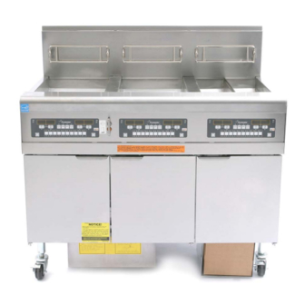
CHAPTER 1: SERVICE PROCEDURES Functional Description BIGLA30 Series LOV™ gas fryers contain a welded stainless steel frypot that is directly heated by a high efficiency infrared burner system, requiring approximately 43% less energy than conventional burners to cook the same volume. -
Page 7: Interface Board
Interface Board All fryers in this series have an interface board located in the component box behind the control panel. The interface board provides a link between the computer and the fryer’s individual components without requiring excessive wiring, and allows the computer to execute commands from one central point. K2 and K3 are double-pole-double throw (DPDT) relays that supply 24VAC to the ignition and gas valve circuits, as well as 120VAC to the blower motor. -
Page 9: Thermostats
(setpoints). BIGLA30 Series LOV™ gas fryers are also equipped with a high-limit thermostat. In the event that the fryer fails to properly control the oil temperature, the high-limit thermostat prevents the fryer from overheating to the flash point. -
Page 10: Checking The Burner Manifold Gas Pressure
4. Remove the wire and blow through the tube to ensure it is clear. 5. Reinstall the tube and bend it so that the opening is pointing downward. Checking the Burner Manifold Gas Pressure 1. On non-CE fryers only ensure that the gas valve knob is in the OFF position. Honeywell 2. -
Page 11: Measuring Flame Current
CE Standard Burner Manifold Gas Pressures Pressure (mbar) Single Dual Natural Gas Lacq (G20) under 20 mbar Natural Gas Gronique * (G25) under 25 mbar Natural Gas Gronique (G25) under 20 mbar Butane/Propane (G30) at 28/30 or 50 mbar Propane (G31) under 37 or 50 mbar * Belgian G25 = 7,0 mbar (single or dual) Non-CE Standard... -
Page 12: Replacing Fryer Components
2. Disconnect the sensing wire from one of the burner ignitors and connect it to the positive lead of the meter. Connect the negative lead of the meter to the terminal from which the sensing wire was removed. Flame Sensor Wire 3. -
Page 13: Replacing The Interface Board
10. If working on the left frypot, cut the wire tie on the wiring bundle and disconnect the main wiring harness 15-pin connector. 11. Remove the component box mounting screws. 12. Rotate the top of the component box out of the frame and carefully pull it out enough to disconnect the wiring harness plug from the back of the box. -
Page 14: Replacing Or Cleaning A Combustion Air Blower
Flame Sensor Wire Gas Enrichment Tube Ignition Cable Remove the sheet metal screws securing the ignitor to the mounting plate and pull the ignitor from the fryer. Reverse the procedure to install the replacement ignitor. 1.9.6 Replacing or Cleaning a Combustion Air Blower 1. -
Page 15: Adjusting The Air/Gas Mixture
Wrap the motor and wires with plastic wrap or a plastic bag. Blower Housing Blower Wheel 4. Remove the plastic wrap from the blower motor assembly. Reassemble the blower motor assembly and blower housing. Reinstall the blower shield. 5. Reinstall the blower assembly in the fryer and reconnect the wiring disconnected in Step 1. 6. -
Page 16: Replacing A Gas Valve
On non-CE blowers loosen this nut and rotate shutter to open or close air intake. On CE blowers loosen both wing nuts and slide the shutter to adjust the air intake. 1.9.8 Replacing a Gas Valve 1. Disconnect fryer from electrical and gas supplies. 2. -
Page 17: Replacing A Burner Assembly
1.9.9 Replacing a Burner Assembly on fryers built after Oct, 2010. For replacement of burners prior to that call the factory. 1. Disconnect the unit from the electrical and gas supplies. 2. Remove the gas line and enrichment tube using a 7/16” and 5/8” wrench from the front of the burner. It may be necessary to remove the MIB board in some locations. -
Page 18: Replacing The Frypot
1.9.10 Replacing the Filter Motor or Filter Pump 1. Disconnect the unit from the electrical power supply. 2. Remove the filter pan from the unit. 3. Position a container beneath the oil return fitting at the front of the cabinet. Disconnect the flexible oil line from the fitting, allowing any residual oil to drain into the container. -
Page 19: Replacing Frypot Insulation And/Or Upper Burner Rails
9. Remove the two mounting screws on each side of the component box and rotate the top of the box out of the frame. Carefully pull it out enough to disconnect the wiring harness connector from the back of the box. - Page 20 Spacer Spacers Disassembling A Frypot (Full Vat Illustrated) See page 1-17 for reassembly illustration. 11. Remove the upper burner rails (11). NOTE: For the following steps, refer to the frypot exploded view on page 1-16 for component identification. 12. Remove any residual insulation, sealant, and/or oil from the exterior of the frypot. 13.
- Page 21 21. Insert the burners (9) into the rails to ensure the rail spacing and alignments are correct. The burner should slide freely into and out of the rails. The upper rail can be bent slightly to increase or decrease tension on the burner and the edges of the slot can be closed or opened slightly to best fit the burner frame.
-
Page 22: Troubleshooting And Problem Isolation
Re-assembling A Frypot (Full-Vat Illustrated) 1.10 Troubleshooting and Problem Isolation Because it is not feasible to attempt to include in this manual every conceivable problem or trouble condition that might be encountered, this section is intended to provide technicians with a general knowledge of the broad problem categories associated with this equipment, and the probable causes of each. -
Page 23: Heating (Ignition) Failure
1.10.1 Heating (Ignition) Failure Heating (ignition) failure occurs when the ignition module fails to sense a flame within the 4-second time delay period and locks out. When this happens, the module sends 24 VAC through the interface board alarm circuit to the computer. - Page 24 (pressure to the gas valve) is in accordance with the appropriate CE or Non-CE Standard found in Section 2.3 page 2-4 of the BIGLA30 Series LOV™ Gas Fryer Installation and Operation Manual (PN 819- 6286), and that the pressure remains constant throughout all hours of usage. Refer to Section 1.7, Checking the Burner Manifold Gas Pressure in this manual for the procedure for checking the pressure of gas supplied to the burner.
-
Page 25: Improper Temperature Control
300ºF (149ºC) point by pressing the INFO button once when the fryer is on. The test results will be displayed in the computer’s LED panel in minutes and seconds. The maximum acceptable recovery time for BIGLA30 Series LOV™ gas fryers is two minutes and twenty-five seconds . 1.10.5 Filtration Malfunctions The majority of filtration problems arise from operator error. -
Page 26: Leakage
An additional set of operator troubleshooting guides are contained in Chapter 7 of the BIGLA30 Series Installation and Operation Manual. It is suggested that service technicians thoroughly familiarize themselves with both sets. - Page 27 24 VAC is present on interface board J3 pin 9 (LED 5 (GV)) and, on dual units, on J1 pin 9 (LED 1 (GV)). 1. If 24 VAC is not present across the gas valve main coil (MV terminals), probable causes are an open high-limit thermostat or a failed wire between the interface board and gas valve.
-
Page 28: Troubleshooting The Gas Valve
1.11.2 Troubleshooting the Gas Valve Prior to checking for problems associated with the gas valve, ensure that the unit is calling for heat. Also, for non- CE units, verify that the gas valve is in the ON position. The following processes will assist you in troubleshooting the gas valve and ruling it out as a probable cause: ... -
Page 29: Troubleshooting The Temperature Probe
1. If incoming gas pressure is not correct, the probable cause is a problem with the gas supply to fryer. 2. If incoming gas pressure is correct, check the burner manifold gas pressure and compare it to the tables on page 2-7 of the Installation and Operation manual. -
Page 30: Probe Resistance Chart
1.12 Probe Resistance Chart Probe Resistance Chart For use with LOV™ Series fryers manufactured with Minco Thermistor probes only. OHMS OHMS OHMS OHMS OHMS 1059 1204 1350 1493 1634 1070 1216 1361 1503 1644 1080 1226 1371 1514 1654 1091 1237 1381 1524... - Page 31 Problem Probable Causes Corrective Action A. Ensure JIB has oil. Clean crumbs from opening surrounding sensor. C. Check to see that fryer is heating. Fryer temperature must be at setpoint. Check probe resistance. If probe is bad, replace the probe. A.
- Page 32 1.13.2 ATO (Automatic Top-Off) Board Pin Positions and Harnesses Wire Connector From/To Harness # Function Voltage Color 24VAC Black 24VAC Ret RTI Add Solenoid 24VAC Black 24VAC Ret ATO Pump Relay 16VDC JIB Low Reset Black JIB Reset Switch 8074671 24VAC 24VAC RTI Add Solenoid...
-
Page 33: Replacing The Ato Board Or Transformer
1.13.3 Replacing the ATO Board or Transformer Disconnect the fryer from the electrical power supply. Locate the ATO box (see Figure 1 on page 1-27), behind the JIB (Jug In Box). Remove the cover to expose the transformers, relay and LON gateway (if installed) (see Figure 2). -
Page 34: Manually Draining, Refilling Or Filtering Using The Mib Board
Buttons and LED’s Manual – This button is used to toggle between auto and manual filtration mode. A corresponding LED is lit when in Manual mode. When pressed, a message will be sent to all vats, indicating the mode has changed. The following buttons are inoperable in auto mode: Select - This button is used to scroll through available vats, choosing one to be manually filtered. -
Page 35: Mib (Manual Interface Board) Troubleshooting
1.14.2 MIB (Manual Interface Board) Troubleshooting Problem Probable Causes Corrective Action A. Ensure filter pan is fully inserted into fryer. A. Filter pan out of position. If the MIB board displays a “P” the pan is B. Oil level too low. not fully engaged into the pan switch. - Page 36 Problem Probable Causes Corrective Action A. Ensure the CAN bus system is terminated at BOTH ENDS (on the M3000 connector J6 and on the ATO board connector J10) with a resistor equipped 6-pin connector. B. With the computer OFF, press TEMP button and ensure the AIF version appears.
-
Page 37: Mib (Manual Interface Board) Pin Positions And Harnesses
1.14.3 MIB (Manual Interface Board) Pin Positions and Harnesses Connector From/To Harness # Pin # Function Voltage Wire Color Ground Black CAN Lo CAN Hi White M3000 J6 8074546 Ground Black CAN Lo CAN Hi White AIF J5 8074850 5VDC+ 5VDC Black 24VDC... -
Page 38: Mib (Manual Interface Board) Display Characters
1.14.4 MIB (Manual Interface Board) Display Characters A – Auto Mode – Auto Filtration enabled. E – Drain or return valve is not in desired state. The display will alternate between E and the corresponding vat number. Ensure the actuator is plugged in and an error does not exist. –... -
Page 39: Rti Mib Tests
1.15 RTI (Restaurant Technology Inc.)Service Issues 1.15.1 RTI MIB Tests RTI (Restaurant Technology Inc.) provides fresh and waste bulk oil service for McDonald’s in the United States. The instructions in this manual for using a bulk oil system for filling and discarding oil are for an RTI system only. These instructions may NOT be applicable to other bulk oil systems. -
Page 40: Rti Lov™ Wiring With Rti Switchbox
RED RTI DISPOSE TANK FULL TESTING BETWEEN PINS 2 & 8 J6 MIB SHOULD READ: 24VAC WHEN RTI TANK IS FULL 0 VAC WHEN RTI TANK IS NOT FULL 28.15.3 Frymaster LOV™ Fryer and RTI Bulk Oil System Plumbing Schematic Return Valves Frypots Check... -
Page 41: Rti Lov™ Test Quick Reference
1.15.4 RTI LOV™ TEST QUICK REFERENCE DISPOSE TO WASTE, REFILL VAT FROM BULK: 1. Hold down “Filter” button until computer beeps twice. 2. Scroll down to “Dispose” using “Info" button then press “” button. 3. “Dispose? Yes/No” is displayed.* 4. Press “” to dispose of oil in pot. 5. - Page 42 6. “Press and Hold Yes to Fill / Yes” is displayed. 7. Press and hold down “” to fill pot to desired level. 8. “Filling” is displayed during fill. 9. Release button to stop filling. 10. “Continue Filling? Yes/No” is displayed. 11.
-
Page 43: Aif (Automatic Intermittent Filtration) Service Procedures
1.16 AIF (Automatic Intermittent Filtration) Service Procedures The AIF (Automatic Intermittent Filtration) board controls the actuators that open and close the drain and return valve. The AIF boards are located inside a protective housing under each frypot (see Figure 15). Figure 15 1.16.1 AIF (Automatic Intermittent Filtration) Troubleshooting Problem... - Page 44 1.16.2 AIF (Auto Intermittent Filtration) Actuator Board Pin Positions and Harnesses Wire Connector From/To Harness PN Function Voltage Color Ret + (Open) 24VDC Black Ret – (Closed) 24VDC FV Return Ret Position Purple Ground White Ground White FV AIF RTD FV - Temp Ground White...
-
Page 45: Replacing An Aif (Automatic Intermittent Filtration) Board
1.16.3 Replacing an AIF (Automatic Intermittent Filtration) Board Disconnect the fryer from the electrical power supply. Locate the AIF board to be replaced under a frypot. Mark and unplug the harnesses. The AIF board assembly is held in place with one screw (see Figure 16). Remove the screw and the assembly drops down (see Figure 17) and the tab slides out of the bracket attached to the frypot (see Figure 18). -
Page 46: Replacing A Rotary Actuator
1.16.5 Replacing a Rotary Actuator Disconnect the fryer from the electrical power supply. Locate the actuator to be replaced and mark and unplug the actuator. The actuators are held in place by two allen screws. Loosen the allen screws. It may be necessary to remove a gas line to the burner when removing a drain actuator. -
Page 47: Oil Level Sensor Diagram
cycle 4 seconds on, 4 seconds off. - Check between pin 3 and 2 on the relay board reads 5VDC for air and 0VDC for oil. A common message for a shorted harness or issue is “IS DRAIN CLEAR?” with oil in the filter pan. - Check ground on pin 2 on relay board to stud for a secure ground. - Page 48 Problem Probable Causes Corrective Action Silence the alarm by pressing the button. M3000 displays Recovery time exceeded maximum time Check that fryer is heating properly. RECOVERY limit for two or more cycles. Maximum recovery for gas is 2:25. If this FAULT.
- Page 49 Problem Probable Causes Corrective Action A. Pull filter pan out and fully reinsert into fryer. A. Filter pan is not fully inserted into B. Ensure the filter pan magnet is in place and if missing replace. fryer. M3000 displays C. If the filter pan magnet is fully against B.
-
Page 50: Tech Mode
Problem Probable Causes Corrective Action Check that all harnesses between M3000’s, MIB, AIF and ATO are secure. Ensure 24VDC is present on pins 5 & 6 of J2 on M3000 displays MIB board and on J4 or J5 of AIF board. software for only M3000 Loose or damaged harness Check for loose or broken pins/wires. -
Page 51: Service Required Errors
5. The computer displays CLEAR PASSWORDS on the left and COMPLETE on the right. This clears any passwords set up under levels one and two. Press the button to toggle to FILTER PAD TIME on the left and 25 on the right. (25 hours is the default time to change the pad) Press the ... -
Page 52: M3000 Filter Error Flowchart
1.17.6 M3000 Filter Error Flowchart MESSAGE NORMAL DISPLAYED OPERATION RESUMES Call an Authorized Repair Technician SIXTH CONSECUTIVE FILTER ERROR TECH Fryer returns to ENTERS cook mode for 15 CODE minutes. Change filter pad and ensure filter pan is Fryer returns to pulled out for a cook mode for 4 minimum of 30... -
Page 53: Clogged Drain/Failed Oil Sensor Flowchart
1.17.7 Clogged Drain/Failed Oil Sensor Error Flowchart 1-48... -
Page 54: M3000 Menu Summary Tree
1.17.8 M3000 Menu Summary Tree Reflected below are the major programming sections in the M3000 and the order in which submenu headings will be found under the sections in the Installation and Operation Manual. See section 4.10.2 Adding New Menu Items See section 4.10.3 Storing Menu Items in Product Buttons See section 4.10.4... -
Page 55: M3000 Board Pin Positions And Harnesses
1.17.9 M3000 Board Pin Positions and Harnesses Connector From/To Harness PN Function Voltage Wire Color SD Card 12VAC In 12VAC Ground 12VAC In 12VAC FV Heat Demand V Relay 12VDC DV Heat Demand R/H B/L 12VDC Black Analog Ground L/H B/L 12VDC 8074199 Interface... -
Page 56: Loading And Updating Software Procedures
1.18 Loading and Updating Software Procedures Updating the software takes approximately 30 minutes. The software only needs to be loaded in ONE computer and it will update all the computers and boards in the system. To update the software, follow these steps carefully: 1. -
Page 57: Principal Wiring Connections
1.19 Principal Wiring Connections N.C. PRESSURE SWITCH N.O. (CE AND SOME EXPORT UNITS) LINE VOLTAGE (L1) BLACK TO T2 & J3 PIN 11 GROUND GREEN TO GROUND LINE VOLTAGE (COM) WHITE TO T1 & C5 PIN 1 24VAC TO J1 PIN 8 & J3 PIN 8 FROM TRANSFORMER BOX 12VAC ORANGE... -
Page 58: Wiring Diagrams
1.20 Wiring Diagrams 1.20.1 Main BIGLA230 120V/CE/Export 1-53... -
Page 59: Main Bigla230 Australia
1.20.1.2 Main BIGLA230 250V Australia 1-54... -
Page 60: Main Bigla330
1.20.2 Main BIGLA330 120V/CE/Export 1-55... -
Page 61: Main Bigla330 Australia
1.20.2.2 Main BIGLA330 250V Australia 1-56... -
Page 62: Transformer / Filter Boxes
1.20.3 Transformer / Filter Boxes 1.20.3.1 BIGLA230 and 430 Transformer / Filter Box (Domestic) 1-57... -
Page 63: Bigla230 And 430 Transformer/Filter Box (International)
1.20.3.2 BIGLA230 and 430 Transformer / Filter Box (International) 1-58... -
Page 64: Bigla330 Transformer/Filter Box (Domestic)
1.20.3.3 BIGLA330 Transformer / Filter Box (Domestic) 1-59... -
Page 65: Bigla330 Transformer/Filter Box (International)
1.20.3.4 BIGLA330 Transformer / Filter Box (International) 1-60... -
Page 66: Simplified Wiring Diagrams
1.21 Simplified Wiring Diagrams 1.21.1 BIGLA30 Series LOV™ Simplified Wiring with LON 1-61... -
Page 67: Bigla30 Series Lov™ Simplified Wiring Without Lon
1.21.1.2 BIGLA30 Series LOV™ Simplified Wiring without LON 1-62... -
Page 68: Bigla30 Series Lov Data Network Flowchart
1.21.2 BIGLA30 Series LOV™ Data Network Flowchart 1-63... -
Page 69: Alternate Time Delay Relay Wiring Diagrams
1.22 Alternate 7 sec. Time Delay Relay Wiring Diagrams PN 8074934 220V-250V (Intl. Units), PN 8074812 120V (US, Canada & Mexico) 1-64... -
Page 70: Solid/Semi-Solid Shortening
1.23 Solid/Semi-Solid Shortening 1.23.1 Shortening Melting Unit Wiring Diagram prior to March 2012 1-65... -
Page 71: Shortening Melting Unit Wiring Diagram After Mar. 2012
1.23.2 Shortening Melting Unit Wiring Diagram after March 2012 1-66... -
Page 72: Bigla230/430 120V/Ce/Export Solid Shortening
1.23.3 BIGLA230/430 120V/CE/Export Solid Shortening 1-67... -
Page 73: Bigla330 120V/Ce/Export Solid Shortening
1.23.4 BIGLA330 120V/CE/Export Solid Shortening 1-68... -
Page 74: Capable Control Ignition Module Wiring Diagrams
1.24 Capable Controls Ignition Module Wiring Diagrams 1-69... - Page 75 THIS PAGE INTENTIONALLY LEFT BLANK...
- Page 76 FRYMASTER 8700 LINE AVENUE, SHREVEPORT, LA 71106‐6800 318‐865‐1711 844‐724‐CARE (2273) WWW.FRYMASTER.COM EMAIL: SERVICE@FRYMASTER.COM *8196316* Every new piece of Manitowoc Foodservice equipment comes with KitchenCare™ and you choose the level of service that meets your operational needs from one restaurant to multiple locations. StarCare – Warranty & lifetime service, certified OEM parts, global parts inventory, performance audited ExtraCare –...
Need help?
Do you have a question about the BIGLA30 Series and is the answer not in the manual?
Questions and answers