Frymaster BIPH55 Series Operator's Manual
Frymaster gas fryer operator's manual
Hide thumbs
Also See for BIPH55 Series:
- Maintenance requirement card (20 pages) ,
- Service manual (90 pages) ,
- Service manual (90 pages)
Table of Contents
Advertisement
This equipment chapter is to be
installed in the Fryer Section of the
Equipment Manual.
MANUFACTURED
BY
P.O. BOX 51000
SHREVEPORT, LOUISIANA 71135-1000
PHONE: 1-318-865-1711
TOLL FREE: 1-800-551-8633
1-800-24 FRYER
FAX: 1-318-219-7135
WARRANTY STATEMENT ..................................................................................................Page i
INTRODUCTION ..................................................................................................................Page 1-1
INSTALLATION INSTRUCTIONS .......................................................................................Page 2-1
OPERATING INSTRUCTIONS ............................................................................................Page 3-1
OPERATING THE BUILT IN FILTRATION SYSTEM ..........................................................Page 4-1
PREVENTIVE MAINTENANCE............................................................................................Page 5-1
OPERATOR TROUBLESHOOTING ....................................................................................Page 6-1
TEL 318-865-1711 FAX (Parts) 318-219-7140 (Tech Support) 318-219-7135
PRINTED IN THE UNITED STATES
www.frymaster.com
OPERATOR'S MANUAL
FRYMASTER BIPH55/MPH55 SERIES
TABLE OF CONTENTS
Frymaster, L.L.C. 8700 Line Avenue 71106, 5489 Campus Drive 71129
P.O. Box 51000, Shreveport, Louisiana 71135-1000
SERVICE HOTLINE
1-800-24-FRYER
Email:
service@frymaster.com
GAS FRYER
Do Not Store or use gasoline or other
flammable vapors and liquids in the
vicinity of this or any other appliance.
FOR YOUR SAFETY
OCTOBER 2005
*8196087*
Advertisement
Table of Contents

Related Manuals for Frymaster BIPH55 Series


Summary of Contents for Frymaster BIPH55 Series
-
Page 1: Table Of Contents
OPERATING INSTRUCTIONS ...Page 3-1 OPERATING THE BUILT IN FILTRATION SYSTEM ...Page 4-1 PREVENTIVE MAINTENANCE...Page 5-1 OPERATOR TROUBLESHOOTING ...Page 6-1 Frymaster, L.L.C. 8700 Line Avenue 71106, 5489 Campus Drive 71129 TEL 318-865-1711 FAX (Parts) 318-219-7140 (Tech Support) 318-219-7135 PRINTED IN THE UNITED STATES www.frymaster.com OPERATOR’S MANUAL... - Page 2 IF, DURING THE WARRANTY PERIOD, THE CUSTOMER USES A PART FOR THIS ENODIS EQUIPMENT OTHER THAN AN UNMODIFIED NEW OR RECYCLED PART PURCHASED DIRECTLY FROM FRYMASTER DEAN, OR ANY OF ITS AUTHORIZED SERVICE CENTERS, AND/OR THE PART BEING USED IS MODIFIED FROM ITS ORIGINAL CONFIGURATION, THIS WARRANTY WILL BE VOID.
- Page 3 If a flexible gas line is used, an additional restraining cable must be connected at all times when the fryer is in use. The front ledge of the fryer is not a step! Do not stand on the fryer. Serious injury can result from slips or contact with the hot oil.
-
Page 4: Warranty Statement
3. If any parts, except fuses and filter O-rings, become defective during the first year after installation date, Frymaster will also pay straight-time labor costs to replace the part, plus up to 100 miles/160 km of travel (50 miles/80 km each way). -
Page 5: Parts Return
Labor is charged to the store. The third year, warranty will cover the part at a reduced cost of $90.00. No labor or handling will be covered. 2. During this warranty period, Frymaster will replace a returned defective cooking computer with a new or factory rebuilt and functionally operative units. -
Page 6: Chapter 1: Introduction
100 VAC to 240 VAC. BIPH55 and MPH55 fryers are shipped completely assembled. All fryers are shipped with a package of standard accessories. Each fryer is adjusted, tested, and inspected at the factory before crating for shipment. - Page 7 DANGER boxes contain information about actions or conditions that may cause or result in injury to personnel, and which may cause damage to your system and/or cause your Your fryer is equipped with automatic safety features: 1. High temperature detection shuts off gas to the burner assembly should the controlling thermostat fail.
-
Page 8: Qualified Service Personnel
QUALIFIED SERVICE PERSONNEL Qualified service personnel are those who are familiar with Frymaster equipment and who have been authorized by Frymaster, L.L.C. to perform service on the equipment. All authorized service personnel are required to be equipped with a complete set of service and parts manuals, and to stock a minimum amount of parts for Frymaster equipment. - Page 9 Manual. Parts orders may be placed directly with your local FASC or distributor. Included with fryers when shipped from the factory is a list of Frymaster FASCs. If you do not have access to this list, contact the Frymaster Service Department at 1-800-551-8633 or 1-318-865-1711.
- Page 10 Service information may be obtained by contacting your local FASC/Distributor. Service may also be obtained by calling the Frymaster Service Department at 1-800-551-8633 or 1-318-865-1711. When requesting service, please have the following information ready: Model Number: Serial Number: Type of Gas:...
-
Page 11: Chapter 2: Installation Instructions
Failure to use qualified, licensed, and/or authorized installation or service personnel (as de- fined in Section 1.6 of this manual) to install, convert to another gas type or otherwise service this equipment will void the Frymaster warranty and may result in damage to the equipment or injury to personnel. -
Page 12: National Code Requirements
(450 mm) should be maintained between the flue outlet and the lower edge of the grease filter.” Frymaster recommends that the minimum distance be 24 in. (600 mm) from the flue outlet to the bottom edge of the filter when the appliance consumes more than 120,000 BTU per hour. - Page 13 If a flexible gas hose is used, a restraining cable must be connected at all times when the fryer is in use. The restraining cable and installation instructions are packed with the flexible hose in the accessories box that was shipped with your unit.
- Page 14 The appliance area must be kept free and clear of combustible material at all times. 3. Frymaster recommends that the minimum distance from the flue outlet to the bottom edge of the hood be 24 in. (600 mm) when the appliance consumes more than 120,000 BTU per hour.
- Page 15 7. For fryers equipped with a FootPrint Pro system (BIPH55 models) plug the electrical cord(s) into a power receptacle behind the fryer. Connection to Gas Line Before connecting new pipe to this appliance, the pipe must be blown out thor- oughly to remove all foreign material.
- Page 16 The Pro Series H55 gas fryer has received the CE mark for the countries and gas categories indicated in the table below. NOTE: The nominal heat input (QN) is 21kW except for AT, DE, LU and category 3P/B, which is 23kW.
- Page 17 2. Open the gas supply to the fryer and check all piping, fittings, and gas connections for leaks. A soap solution should be used for this purpose.
- Page 18 5. Check the programmed temperature thermostat setting. (Refer to the separate M2000 Manual furnished with your unit for the setpoint programming instructions for your particular controller.) Converting to Another Gas Type This appliance was configured at the factory for a specific type of gas. Converting from one type of gas to another requires the installation of specific gas-conversion components.
- Page 19 After the Fryers Are Positioned At the Frying Station 1. Once the fryer has been positioned at the frying station, use a carpenter’s level placed across the top of the frypot to verify that the unit is level, both side-to-side and front-to-back.
-
Page 20: Chapter 3: Operating Instructions
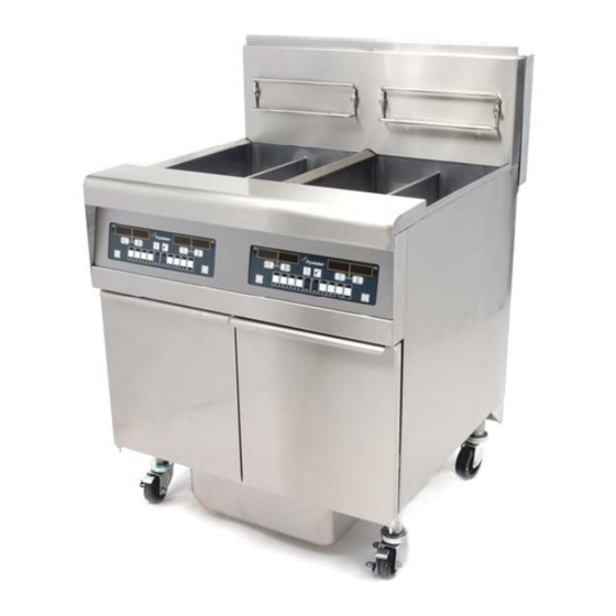
BIPH55 / MPH55 SERIES GAS FRYER CHAPTER 3: OPERATING INSTRUCTIONS FINDING YOUR WAY AROUND THE BIPH55 SERIES GAS FRYER Flue Cap Basket Hangers Flue Control Panel (M2000 Top Cap Computer Shown) Gas Valve Gas Valve Combustion Blower Filter Control Handles... - Page 21 If this is the first time the fryer is being used after installation, refer to the frypot Boil- Out Procedure in Section 5.3.2.1 of this manual.
- Page 22 3. If the burners fail to light, press the ON/OFF switch to the OFF position and wait 60 seconds. Repeat step 2. 4. The fryer will automatically enter the melt cycle mode if the frypot temperature is below 180ºF (82ºC). (NOTE: During the melt cycle, the burners will repeatedly fire for a few seconds, then go out for a longer period.) When the frypot temperature reaches 180ºF (82ºC), the unit will...
- Page 23 1. Place the computer ON/OFF switch in the OFF position and put the frypot covers in place. When shutting the fryers down at closing time: 1. Place the computer ON/OFF switch in the OFF position to turn the fryer off. For CE Fryers Placing the ON/OFF switch in the OFF position also turns off the gas valve.
-
Page 24: Chapter 4: Filtration Instructions
When draining oil into a disposal unit or portable filter unit, do not fill above the maximum fill line located on the container. If your fryer is not equipped with a built-in filtration system, the oil must be drained into another suitable container. (For safe, convenient draining and disposal of used oil, Frymaster recommends using the McDonald’s Shortening Disposal Unit (MSDU). - Page 25 DO NOT hammer on the drain valve with the cleanout rod or other objects. Damage to the ball inside will result in leaks and will void the Frymaster warranty. 4. After draining the oil, clean all food particles and residual oil from the frypot. BE CAREFUL, this material may still cause severe burns if it comes in contact with bare skin.
- Page 26 DO NOT use filter powder with the pad! 5. Replace the crumb tray in the filter pan. Push the filter pan back into the fryer, positioning it all the way to the back of the cabinet. The filtration system is now ready for use.
- Page 27 4. After the oil is filtered (about 5 minutes), close the drain valve and allow the fryer to refill. Let the filter pump run 15 to 30 seconds after the oil begins to bubble in the frypot then turn the filter off but rotating the handle up.
- Page 28 When your oil has reached the end of its usable life, drain the oil into an appropriate container for transport to the disposal container. Frymaster recommends the use of the McDonald’s Shortening Disposal Unit (MSDU). NOTE: If using an MSDU built before January 2004, the filter pan cover must be removed to allow the unit to be positioned beneath the drain.
-
Page 29: Chapter 5: Preventive Maintenance
5.2.2 Clean Fryer Cabinet Inside and Out Clean inside the fryer cabinet with dry, clean cloth. Wipe all accessible metal surfaces and compo- nents to remove accumulations of oil and dust. -
Page 30: Weekly Checks And Service
5.3.2.1 Boiling Out the Frypot Before the fryer is first used, it should be boiled out to ensure that residue from the manufacturing process has been eliminated. Also, during normal usage of your fryer, a deposit of carbonized oil or shortening will gradually form on the inside of the frypot. -
Page 31: Monthly Checks And Service
MONTHLY CHECKS AND SERVICE 5.4.1 Check M2000 Computer Set Point Accuracy 1. Insert a good-grade thermometer or pyrometer probe into the oil, with the end touching the fryer temperature-sensing probe. 2. When the computer display shows a series of dashes “----” or a product name (indicating that the frypot contents are within the cooking range), press the temperature of the oil or shortening as sensed by the temperature probe. - Page 32 Wiring connection 2. Remove the three fasteners that secure the blower motor assembly to the blower housing, and separate the two components. (See Figure 2) 3. Wrap the motor with plastic wrap to prevent water from entering it. Spray degreaser or detergent on the blower wheel and the blower housing.
- Page 33 5. Reinstall the blower shield or shield assembly. 6. Light the fryer in accordance with the procedure described in Chapter 3, Section 3.1. 7. After the burners have been lit for at least 90 seconds, observe the flames through the burner viewing ports located on each side of the combustion air blower.
-
Page 34: Semi-Annual Checks And Service
Annual/Periodic System Inspection This appliance should be inspected and adjusted periodically by qualified service personnel as part of a regular kitchen maintenance program. Frymaster recommends that a Factory Authorized Service Technician inspect this appliance at least annually as follows: 5.7.1 Fryer •... - Page 35 • Verify that component box components (i.e. computer, transformers, relays, interface boards, etc.) are in good condition and free from oil and other debris. Inspect the component box wiring and verify that connections are tight and that wiring is in good condition. •...
-
Page 36: Chapter 6: Operator Troubleshooting
If you are in doubt as to the proper action to take, do not hesitate to call the Frymaster Technical Service Department or your local Frymaster Factory Authorized Service Center for assistance. - Page 37 Dirty or obstructed combustion air blower. recovery is slow when cooking. CORRECTIVE ACTION A. Verify that the fryer is plugged in and that the circuit breaker is not tripped. B. Call FASC. C. Call FASC. D. If any component in the power...
- Page 38 M2000 display is in wrong temperature Incorrect display option programmed. scale (Fahrenheit or Celsius). M2000 display Fryer is 15ºF (8ºC) above setpoint. shows HI. Frypot temperature is more than M2000 display 410ºF (210ºC) or, in CE countries, shows HOT. 395ºF (202ºC).
- Page 39 Corrective Action This display is normal when the fryer is first turned on and may appear for a short while if a large batch of frozen product is added to the frypot. If the display never goes out, the fryer is not heating.
- Page 40 Pump stops during pump. filtering. B. Failed filter handle microswitch. Test: If this is a multi-pot fryer, attempt to operate the pump using a different handle. If the pump starts, the handle microswitch is either out of alignment or has failed.
- Page 41 PROBLEM PROBABLE CAUSES C. Blockage in filter pump. Test: Close the drain valve. Place the filter handle in the OFF position, allow the pump to cool for at least 45 minutes, and then press the reset Continued from button on the pump motor. Pull the Previous page filter pan from the unit.
- Page 42 Replacing the Controller or Controller Wiring Harness 1. Disconnect the fryer from the electrical power supply. 2. The controller bezel is held in place by tabs at the top and bottom. Slide the bezel up to disengage the lower tabs. Then slide the bezel down to disengage the upper tabs.
- Page 43 THIS PAGE INTENTIONALLY LEFT BLANK...
- Page 44 Frymaster, L.L.C., 8700 Line Avenue, PO Box 51000, Shreveport, Louisiana 71135-1000 Shipping Address: 8700 Line Avenue, Shreveport, Louisiana 71106 TEL 1-318-865-1711 FAX (Parts) 1-318-219-7140 FAX (Tech Support) 1-318-219-7135 SERVICE HOTLINE 819-6087 PRINTED IN THE UNITED STATES 1-800-551-8633 OCT 2005...
Need help?
Do you have a question about the BIPH55 Series and is the answer not in the manual?
Questions and answers