LG Chem RESU10H Installation Manual
Type-r 9.8kwh 400v resu series
Hide thumbs
Also See for RESU10H:
- Installation manual (36 pages) ,
- Installer's manual (26 pages) ,
- Installation manual (35 pages)
Table of Contents
Advertisement
Quick Links
Download this manual
See also:
Installation Manual
Advertisement
Table of Contents

Related Manuals for LG Chem RESU10H


Summary of Contents for LG Chem RESU10H
- Page 1 Installation Manual for RESU10H (Type-R)
- Page 2 The information included in this manual is accurate at the time of publication. However, this manual is subject to change without prior notice. In addition, the concepts and installation instructions. Please note the image shown is for illustration purposes only. CAUTION After installation, the installer must explain the User Guide to the end-user.
-
Page 3: Table Of Contents
Contents Safety Symbols ........................5 Safety instructions ....................6 1.2.1 General safety precautions ................ 6 1.2.2 Battery handling guide ................6 1.2.3 Response to emergency situations ............8 Warning label ......................9 Quali ed personnel ..................... 10 Product Introduction Technical data ....................... 11 2.1.1 Dimensions and weight ................ - Page 4 Contents Commissioning LED indicators ..................... 27 Powering up the battery pack ................28 Shutting o the battery pack ................28 Troubleshooting Troubleshooting ....................29 Uninstallation & Return Return/replacement instructions ................30 6.1.1 Uninstallation from the wall ..............30 6.1.2 Contact information .................. 32...
-
Page 5: Safety
1 Safety Symbols Caution, risk of electric shock Install the product out of reach of children. Read the instruction manual before starting installation and operation. Heavy weight may cause serious injury to the back. Do not dispose of the product with household wastes. Recyclable Disconnect the equipment before carrying out maintenance or repair. -
Page 6: Safety Instructions
Safety Safety instructions For safety reasons, installers are responsible for familiarizing themselves with the contents of this document and all warnings before performing installation. 1.2.1 General safety precautions Over-voltages or wrong wiring can damage the battery pack and cause de agration, which can be extremely dangerous. - Page 7 Safety • Do not disconnect, disassemble or repair by unqualified personnel. Services must be made by qualified personnel only. Do not damage the unit in such ways as dropping, deforming, impacting, cutting • or penetrating with a sharp object. It may cause a leakage of electrolyte or fire. •...
-
Page 8: Response To Emergency Situations
Safety 1.2.3 Response to emergency situations The RESU10H battery pack comprises multiple batteries that are designed to prevent hazards resulting from failures. However, LG Chem cannot guarantee their absolute safety. • If a user happens to be exposed to internal materials of the battery cell due to damage on the outer casing, the following actions are recommended. -
Page 9: Warning Label
If the FAULT LED shows, refer to the User Guide to : open the wiring box; turn off the toggle switch and the circuit breaker; WARNING ① ② then contact LG Chem or your service provider. Otherwise, the battery may not operate properly. ③ 2. Product label 3. Traceability label... -
Page 10: Quali Ed Personnel
Safety Qualified personnel This guide and the tasks and procedures described herein are intended for use by skilled workers only. A skilled worker is defined as a trained and qualified electrician or installer who has all of the following skills and experience: • Knowledge of the functional principles and operation of on-grid and off-grid (backup) systems. -
Page 11: Product Introduction
2 Product Introduction Technical data 2.1.1 Dimensions and weight RESU10H EVESPBO0100B0 Width 744 mm (29.3”) Height 907 mm (35.7”) Depth 206 mm (8.1”) Weight 97 kg (214 lbs) 907 mm 1) A battery pack’s weight (35.7”) varies slightly. 744 mm (29.3”) -
Page 12: Performance
※ Test Conditions - Temperature 25°C, at the beginning of life. 1) Battery Cell Only energy capacity at Depth of Discharge 95%. 2) LG Chem recommends 3.3kW for maximizing battery lifetime. 3) Peak Current excludes repeated short duration(less than 5 sec. of current pattern). -
Page 13: Feature
Product Introduction Feature • Compact Energy storage unit for domestic photovoltaic system compatibility • Residential 400V DC battery pack system : Daily cycle residential battery system • No Additional Devices : Aux Power and Protection Devices* Included *Protection Devices - Inverter interface (between Battery Pack and Inverter) : Over Voltage, Over Current, External Short Circuit, Reverse Polarity, Inrush Current, Ground Fault , Over Temp. -
Page 14: Installation
3 Installation Mechanical requirements 3.1.1 Unboxing the package 1. Cut the packing tape and open the carton. 2. Pull out other items. Take them out and check if any item is missing. See Package items on section 3.1.2... -
Page 15: Unboxing The Package
Installation 3. Remove the wall bracket guide pad & cushioning pad. 4. Remove the side pad. 5. Pull out the battery pack using handles and stand it up. (Lift handles are sold optionally for this product.) CAUTION According to regional regulations, several people may be required for moving equipment. -
Page 16: Items In The Package
Installation 3.1.2 Items in the package These items are included in the package. Battery pack Wall bracket M6 wall mount Manual User Guide bolts (2EA) 3.1.3 Installation locations Required : • There must be no highly ammable or explosive materials nearby. •... -
Page 17: Clearance
Installation 3.1.4 Clearance • Recommended clearances (>12") for the left, right, top and bottom of the 300mm (12") the proper ventilation and installer convenience. 300mm 300mm (12") (12") 600mm (24") Floor 3.1.5 Tools & safety gears required • Tools The following tools are required to install the battery pack : Precision screwdriver M6 Torque wrench Inclinometer... - Page 18 Installation • Safety gears for personal protection It is recommended to wear the following safety gears when handling the battery pack. Insulated gloves Safety goggles Safety shoes NOTE RESU HV is heavy and challenging to lift. Lift handles are recommended.
-
Page 19: Mounting Bracket
Installation 3.1.6 Mounting bracket When installing the battery pack on a wall, make sure that the wall is capable of supporting the weight of the battery pack. To mount the battery pack on a wall, take the following steps : 1. -
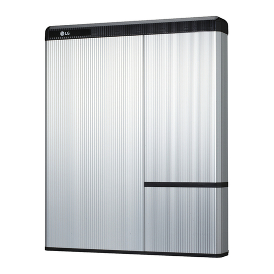
Page 20: Appearance And Dimension
Installation 3.1.7 Appearance and dimension • Appearance Proper handling and care is recommended as disassembly, change of color, battery pack. • Pack appearance and dimension 907mm (35.7") Color and Material 744mm - Front / Rear Cover : Silver or Gold, Aluminum (29.3") - Top / Bottom / LED Cover : Black, Plastic 206mm... -
Page 21: Installing The Battery Pack
Installation 3.1.9 Installing the battery pack CAUTION connecting the power cable to the battery pack. 1. Fix the lift handles to the hex-socket screws on the rear (marked position) of both left and right sides. 2. Mount the wall bracket to a wall. Tighten the screws, ensuring that they are horizontally driven into the wall. - Page 22 Installation 4. Tighten the two hex-socket screws enclosed and remove the lift handles. The nuts for these screws are welded to the battery pack chassis. Tighten to a torque of 5 N m using the M6 • torque wrench. 5. Press the two buttons and pull the two latches (marked position) on the rear side of the wiring box cover (hinged door).
- Page 23 Installation 7. Loosen the screw (marked position), and remove the transparent protection cover. CAUTION If you lose or break a protection cover, that violates NEC Regulation. Transparent protection cover 8. Remove the cap on hole in the bottom side, and assemble the ¾" conduit plug.
-
Page 24: Cable Connection
Installation Cable connection 1. Power (wire AWG, Max length, Pinning) a) Connect the ground wire to terminal 1. b) Connect the negative line of the power cable to terminal 2. c) Connect the positive line of the power cable to terminal 3. For the speci cations of the terminal ※... - Page 25 Installation 4. Auxiliary power ON/OFF switch (for shipping and storage) Turn on the auxiliary power switch. Must turn o to reduce self-discharge ※ of battery during shipping and storage. 5. Close the transparent protection cover and tighten the screw. (Marked position) Close the wiring box cover.
-
Page 26: Auxiliary Power Switch And Spring Terminal Blocks
Installation 3.2.1 Auxiliary power switch and spring terminal blocks Auxiliary power switch Power terminal block Communication terminal block Auxiliary power switch • SPG-Electronics • Rocker Switch • SPG-R36 2. Power terminal block • Max cable length: 10m (35ft) • Cable Type : 4~10㎟ (8~12AWG) •... -
Page 27: Commissioning
4 Commissioning LED indicators The LED indicators on the front of the battery pack show its operational state as follows: LED Status Action Power on, Idle Charging Discharging Fault There are four LED indicators on the front of the battery packs to show its operating status. -
Page 28: Powering Up The Battery Pack
CAUTION If it stays o , indicates FAULT or fails to operate, do not use the battery pack and contact LG Chem (page 32) or your distributor. Shutting o the battery pack To shut down the battery pack, follow these steps : Turn o the inverter. -
Page 29: Troubleshooting
For a serious warning, if no proper corrective actions are taken by the inverter, the battery pack’s circuit breaker automatically trips to protect itself. CAUTION If the battery pack or the inverter indicates FAULT or fails to operate, contact LG Chem (page 32) or your distributor immediately. -
Page 30: Uninstallation & Return
6 Uninstallation & Return Return/replacement instructions 6.1.1 Uninstallation from the wall 1. Switch OFF the Inverter before starting the uninstallation of the battery pack. 2. Press the two buttons and pull the two latches (marked position) on the rear. 3. Open the wiring box cover (about 2~10 degrees), and pull to remove it. - Page 31 Uninstallation & Return Switch o the circuit breaker. ※ If you have Auxiliay Power ON/OFF switch, turn o Auxiliay Power switch. CAUTION while the battery is in operation. 6. Disconnect the communication cable from the communication port. 7. Disconnect the power cable from the terminal block.
-
Page 32: Contact Information
If the battery pack seems to be damaged, contact LG Chem or your distributor. Use the contacts below for technical assistance. These phone numbers are available only during business hours on weekdays. - Page 33 Keep this manual for later use. © 2016 LG Chem FKI Tower 37th, 24, Yeoui-daero, Yeongdeungpo-gu, Seoul 07320, Rep. of KOR. TEL : (82) 2-3773-1114 FAX : (82) 2-3773-7005 http://www.lgesspartner.com http://www.lgchem.com...
Need help?
Do you have a question about the RESU10H and is the answer not in the manual?
Questions and answers