LG Chem RESU10H Installation Manual
Hide thumbs
Also See for RESU10H:
- Installation manual (35 pages) ,
- Installer's manual (26 pages) ,
- Installation manual (35 pages)
Table of Contents
Advertisement
Quick Links
Advertisement
Table of Contents

Subscribe to Our Youtube Channel
Related Manuals for LG Chem RESU10H


Summary of Contents for LG Chem RESU10H
- Page 1 INSTALLATION MANUAL...
- Page 2 The information included in this manual is accurate at the time of publication. However, this manual is subject to change without prior notice. In addition, the illustrations in this manual are meant only to help explain system configuration concepts and installation instructions. Please note the image shown is for illustration purposes only.
-
Page 3: Table Of Contents
Contents Safety Symbols ........................5 Safety instructions ....................6 1.2.1 General safety precautions ................ 6 1.2.2 Battery handling guide ................6 1.2.3 Response to emergency situations ............8 Warning label ......................9 Qualified personnel ..................... 10 Product Introduction Technical data ....................... 11 2.1.1 Dimensions and weight ................ - Page 4 Contents Commissioning LED status ......................29 4.1.1 LED indicators ................... 29 Functionality Powering up the system ..................30 5.2 Shutting off the system ..................30 5.3 Emergency procedure ..................31 5.3.1 Fire ......................31 5.3.2 Damaged or smoking batteries ............... 31 Troubleshooting Troubleshooting ....................
-
Page 5: Safety
1 Safety Symbols Caution, risk of electric shock Do not place nor install near flammable or explosive materials. Install the product out of reach of children. Read the instruction manual before starting installation and operation. Heavy weight may cause serious injury to the back. Do not dispose of the product with household wastes. -
Page 6: Safety Instructions
Safety Safety instructions For safety reasons, installers are responsible for familiarizing themselves with the contents of this document and all warnings before performing installation. 1.2.1 General safety precautions which can be extremely dangerous. install in places where explosive gas or chemicals are present. The utility grid, solar input, and battery voltage must be disconnected from the Battery Pack is not user serviceable. - Page 7 Safety • All types of breakdown of the product may lead to a leakage of electrolyte or flammable gas. • Do not place the product nearby flammables. It may lead to fire or explosion in case of accident. • Keep out of reach of children or animals. • Keep the product away from direct liquid.
-
Page 8: Response To Emergency Situations
Safety 1.2.3 Response to emergency situations • If a user happens to be exposed to internal materials of the battery cell due to damage on the outer casing, the following actions are recommended. Inhalation : Leave the contaminated area immediately and seek medical attention. Eye contact : Rinse eyes with running water for 15 minutes and seek medical attention. -
Page 9: Warning Label
Safety Warning label Warning labels and other relevant labels are attached to the inside of the battery pack. 1. Warning label 2. Product label 3. Traceability label... -
Page 10: Qualified Personnel
Safety Qualified personnel This guide and the tasks and procedures described herein are intended for use by skilled workers only. A skilled worker is defined as a trained and qualified electrician or installer who has all of the following skills and experience: • Knowledge of the functional principles and operation of on-grid and off-grid (backup) systems. -
Page 11: Product Introduction
2 Product Introduction Technical data 2.1.1 Dimensions and weight RESU10H EVESPBO0100A0 Width 744 mm (29.3”) Height 907 mm (35.7”) Depth 206 mm (8.1”) Weight 99.8 kg (220 lbs) 1) A battery pack’s weight varies slightly. -
Page 12: Performance
Class 9 Transportation UN38.3 (UNDOT) Ingress Rating IP55 ※ Test Conditions - Temperature 25°C 1) Values for Battery only. 2) LG Chem recommends 3.3kW for maximizing battery lifetime. 3) Peak Current excludes repeated short duration(less than 5 sec. of current pattern). -
Page 13: Feature
Product Introduction Feature • Compact Energy storage unit for domestic photovoltaic system compatibility • Residential 400V DC battery pack system : Daily cycle residential battery system • No Additional Devices : Aux Power and Protection Devices* Included *Protection Devices - Inverter interface (between Battery Pack and Inverter) : Over Voltage, Over Current, External Short Circuit, Reverse Polarity, Inrush Current, Ground Fault , Over Temp. -
Page 14: Handling
Product Introduction 2.3.2 Handling • Do not step on the product or the product package. The product may be damaged. • A ventilated area is strongly recommended for handling the prouct. • Store the product on a flat surface. • There must be no flammable or explosive materials nearby. • The temperature and humidity should be maintained at a constant level. -
Page 15: Installation
3 Installation Mechanical requirements 3.1.1 Unboxing the package 1. Lift the cover upwards to remove it. 2. Pull out other items. Take them out and check if any item is missing. See Package items on section 3.1.2... - Page 16 Installation 3. Remove the wall bracket guide pad & cushioning pad. 4. Remove the side cover. 5. Pull out the battery pack using handles and stand it up. (Lift handles are sold optionally for this product) CAUTION According to regional regulations, several people may be required for moving equipment.
-
Page 17: Items In The Package
Installation 3.1.2 Items in the package These items are included in the package. Battery pack Wall bracket M6 wall mount Manual bolts (2EA) 3.1.3 Installation locations • The building should be designed to withstand earthquakes. • A waterproof and properly ventilated area is recommended. (IP55) • Install the product on a flat wall. -
Page 18: Clearance
Installation 3.1.4 Clearance • Recommended clearances (>12") for the left, right, top and bottom of the 300mm (12") product is shown in the figure for the proper ventilation and installer convenience. 300mm 300mm (12") (12") 600mm (24") Floor 3.1.5 Tools & safety gears required • Tools The following tools are required to install the battery pack : Precision screwdriver... -
Page 19: Mounting Bracket
Installation • Safety gears for personal protection It is recommended to wear the following safety gears when handling the battery pack. Insulated gloves Safety goggles Safety shoes 3.1.6 Mounting bracket When installing the battery pack on a wall, make sure that the wall is capable of supporting the weight of the battery pack. - Page 20 Installation To mount the battery pack on a wall, take the following steps : 1. Mark the location on the wall for the holes. 2. Drill holes for fasteners in the wall. 3. Drive the fasteners through the mounting bracket into the holes. •...
-
Page 21: Appearance And Dimension
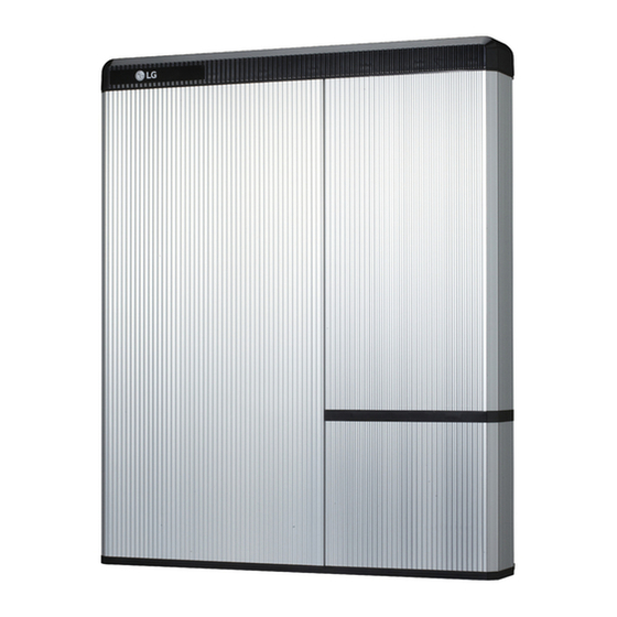
Installation 3.1.7 Appearance and dimension • Appearance Proper handling and care is recommended as disassembly, change of color, scratches, leakage of liquid, and stains may influence the economic value of the battery pack. • Pack appearance and dimension 907mm (35.7") Color and Material 744mm Front / Rear Cover : Silver or Gold, Aluminum... -
Page 22: Installing The Battery Pack
Installation 3.1.9 Installing the battery pack CAUTION Make sure that the inverter AC and DC disconnects are turned off before connecting the power cable to the battery pack. 1. Fix the lift handles to the hex-socket screws on the rear (marked position) of both left and right sides. - Page 23 Installation 4. Tighten the two hex-socket screws enclosed and remove the lift handles. The nuts for these screws are welded to the battery pack chassis. Tighten to a torque of 5 N m using the M6 • torque wrench. 5. Press the two buttons and pull the two latches (marked position) on the rear side of the wiring box cover (hinged door).
- Page 24 Installation 7. Loosen the screw (marked position), and remove the transparent protection cover. CAUTION If you lose or break a protection cover, that violates NEC Regulation. Transparent protection cover 8. Remove the cap on hole in the bottom side, and assemble the ¾" conduit plug.
- Page 25 Installation 10. Power (wire AWG, Max length, Pinning) a) Connect the ground wire to terminal 1. b) Connect the negative line of the power cable to terminal 2. c) Connect the positive line of the power cable to terminal 3. ※...
- Page 26 Installation 13. Reattach the transparent protection cover and tighten with the screw (Marked position) Close the wiring box cover. Reattach battery over the two latchets on the rear.
-
Page 27: Cable Connection
Installation Cable connection 3.2.1 Spring terminal blocks Power terminal block Communication terminal block 1. Power terminal block • Max. cable length: 10m (35ft) • Cable type : 4~10㎟ (10~12AWG) • DC 600V insulated • Pinning ( + ) • Phoenix contact ( - ) •... -
Page 28: Connect/Disconnect The Wire To Connector Sequence
Installation 3.2.2 Connect/disconnect the wire to connector sequence 1. To remove one of the wires from its terminal, insert a small screwdriver into the rectangular hall above the terminal. 2. Apply slight pressure to the screwdriver and at the same time pull out the wire. -
Page 29: Commissioning
4 Commissioning LED status 4.1.1 LED indicators The LED indicators on the front of the battery pack show its operational state as follows: LED status Action Power on, Idle Charging Discharging Fault... -
Page 30: Functionality
5 Functionality Powering up the system Put the battery pack in operation by taking the following steps : 1. Make sure that the circuit breaker switch is in the OFF position. (including Trip position) 2. Move the circuit breaker switch to the ON position to turn on the main battery pack. -
Page 31: Emergency Procedure
Damaged or smoking batteries may pose a danger to people or property. If the battery pack is suspected to be damaged or when smoke comes out from the battery, immediately stay away from it and contact LG Chem for advice and information. -
Page 32: Troubleshooting
CAUTION If the fault LED is on, please contact your local dealer or installer who installed the product or directly contact the LG Chem personnel (page 35) within 24 hours. -
Page 33: Uninstallation & Return
7 Uninstallation & Return Return/replacement instructions 7.1.1 Uninstallation from the wall 1. Switch OFF the Inverter before starting the uninstallation of the battery pack. 2. Press the two buttons and pull the two latches (marked position) on the rear. 3. Open the wiring box cover (about 2~10 degrees), and pull to remove it. - Page 34 Uninstallation & Return 5. Switch off the circuit breaker. ※ If you have Auxiliay Power ON/OFF switch, turn off Auxiliay Power switch. CAUTION Do not turn off the Auxiliary Switch while the battery is in operation. 6. Disconnect the communication cable from the communication port.
-
Page 35: Contact Information
If the battery pack seems to be damaged, contact LG Chem or your distributor. Use the contacts below for technical assistance. These phone numbers are available only during business hours on weekdays. - Page 36 Keep this manual for later use. © 2016 LG Chem LG Twin Towers, 128 Yeoui-daero Yeongdeungpo-gu Seoul, Korea. 07336 TEL : (82) 2-3773-1114 FAX : (82) 2-3773-7005 http://www.lgesspartner.com http://www.lgchem.com...
Need help?
Do you have a question about the RESU10H and is the answer not in the manual?
Questions and answers