LG Chem RESU10H Installation Manual
Hide thumbs
Also See for RESU10H:
- Installation manual (36 pages) ,
- Installer's manual (26 pages) ,
- Installation manual (8 pages)
Table of Contents
Advertisement
Quick Links
Installation Manual for RESU10H(Type-C)
Compatible Inverter: SMA Sunny Boy Storage
LG Chem strongly advises to take due care in following LGC's RESU10H
installation manual and user guide. A warranty claim is invalid if damage is caused
by human error, inconsistent with the installation manual and/or the user guide.
Version 2.1
Advertisement
Table of Contents
Troubleshooting

Related Manuals for LG Chem RESU10H


Summary of Contents for LG Chem RESU10H
- Page 1 Installation Manual for RESU10H(Type-C) Compatible Inverter: SMA Sunny Boy Storage LG Chem strongly advises to take due care in following LGC’s RESU10H installation manual and user guide. A warranty claim is invalid if damage is caused by human error, inconsistent with the installation manual and/or the user guide.
- Page 2 The information included in this manual is accurate at the time of publication. However, this manual is subject to change without prior notice. In addition, the illustrations in this manual are meant only to help explain system configuration concepts and installation instructions.
-
Page 3: Table Of Contents
Contents Safety ........................5 1.1 Symbols ........................ 5 1.2 Safety instructions ....................6 1.2.1 General safety precautions................6 1.2.2 Battery handling guide ................7 1.2.3 Response to emergency situations .............. 8 1.3 Warning label ......................9 1.4 Qualified personnel ..................... 10 Product Introduction .................... - Page 4 Commissioning ....................... 27 4.1 LED indicators ....................27 4.2 Powering up the battery pack ................28 4.3 Shutting off the battery pack ................28 Troubleshooting ...................... 29 5.1 Troubleshooting ....................30 5.1.1 Post-Installation Check List..............30 5.1.2 Troubleshooting Guideline ............... 30 Uninstallation &...
-
Page 5: Safety
Safety Symbols Caution, risk of electric shock Do not place nor install near flammable or explosive materials Install the product out of reach of children Read the instruction manual before starting installation and operation Heavy weight may cause serious injury to the back Do not dispose of the product with household wastes Recyclable Disconnect the equipment before carrying out maintenance or repair... -
Page 6: Safety Instructions
Do not store the battery pack upside down on the ground. Notify your LG Chem regional contact if the product cannot be installed within 5 months after the manufacturing date. The product may require recharge. If the battery pack is installed in the garage then ensure the product is above the height of the vehicle bumper and/or door ... -
Page 7: Battery Handling Guide
Do not disconnect, disassemble or repair by unqualified personnel. Services must be made by qualified personnel only. Do not step on the product or the product package. The product may be damaged. Do not place any foreign objects on the top of the Battery Pack and on the cooling fin. ... -
Page 8: Response To Emergency Situations
1.2.3. Response to emergency situations The RESU10H battery pack comprises multiple batteries that are designed to prevent hazards resulting from failures. However, LG Chem cannot guarantee their absolute safety. If a user happens to be exposed to internal materials of the battery cell due to damage on the outer casing, the following actions are recommended. -
Page 9: Warning Label
Warning label Warning labels and other relevant labels are attached to the inside of the battery pack. 1. Warning label 2. Product label 3. Traceability label R15563P3SDLT1 1610317001... -
Page 10: Qualified Personnel
Qualified personnel This guide for the tasks and procedures described herein is intended for usage by skilled workers only. A skilled worker is defined as a trained and qualified electrician or installer who has all of the following skills and experience: ... -
Page 11: Product Introduction
2. Product Introduction 2.1 Technical data 2.1.1 Dimensions and weight RESU10H (Type-C) EVESPBO100A0 Width 744 mm (29.3“) Height 907 mm (35.7“) Depth 206 mm (8.1“) 99.8kg(220lbs) 1) A battery pack’s weight varies slightly. -
Page 12: Performance
※ Energy is measured under specific condition from LGC (0.3CCCV/0.3CC). 1) Value for Battery Cell Only(Depth of Discharge 95%). 2) LG Chem recommends 2.1kW for maximum battery lifetime. 3) Peak Current excludes repeated short duration(less than 5 sec. of current pattern). -
Page 13: Feature
2.2 Feature Compact Energy storage unit for domestic photovoltaic system compatibility Residential 400V DC battery pack system : Daily cycle residential battery system No Additional Devices : Protection Devices* Included * Protection Devices - Inverter interface (between Battery Pack and Inverter) : Over Voltage, Over Current, External Short Circuit, Reverse Polarity, Inrush Current, Ground Fault, Over Temp. -
Page 14: Installation
3. Installation 3.1 Mechanical requirements 3.1.1 Unboxing the package 1. Cut the packing tape and open the carton. 2. Pull out other items. Take them out and check if any item is missing. See Package items on section 3.1.2... - Page 15 3. Remove the wall bracket guide pad & cushioning pad & paper pipes (4ea).. 4. Remove the side pad. 5. Pull out the battery pack using handles and stand it up. (Lift handles are sold separately for this product.) CAUTION According to regional regulations, several people may be required for moving equipment.
-
Page 16: Items In The Package
3.1.2 Items in the package These items are included in the package. 3.1.3 Installation locations Required : There must be no highly flammable or explosive materials nearby. The ambient temperature should be within the range of 14 ~ 113°F (-10 ~ 45°C). ... -
Page 17: Clearance
3.1.4 Clearance Recommended clearances for the left, right, top and bottom of the product is shown in the figure for the proper ventilation and installer convenience. 3.1.5 Tools & safety gears required Tools The following tools are required to install the battery pack :... - Page 18 Safety gears for personal protection It is recommended to wear the following safety gears when handling the battery pack.
-
Page 19: Mounting Bracket
3.1.6 Mounting bracket When installing the battery pack on a wall, make sure that the wall is capable of supporting the weight of the battery pack. To mount the battery pack on a wall, take the following steps : 1. Mark the location on the wall for the holes. 2. -
Page 20: Appearance And Dimension
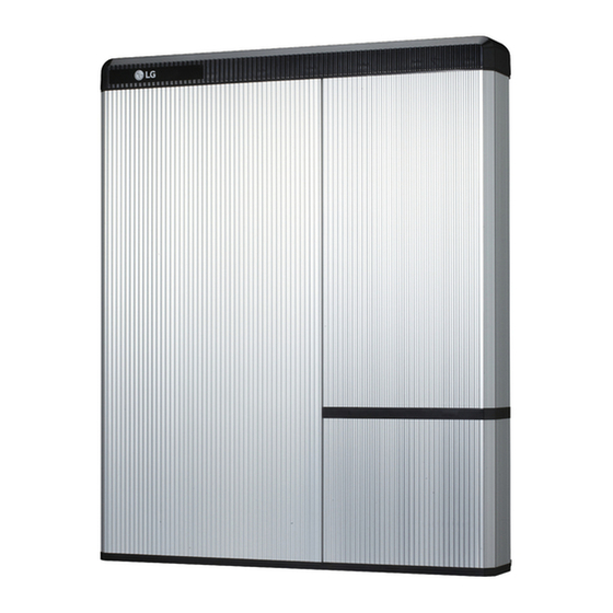
3.1.7 Appearance and dimension Appearance Proper handling and care is recommended as disassembly, change of color, scratches, leakage of liquid, and stains may influence the economic value of the battery pack. Pack appearance and dimension Color and Material - Front / Rear Cover : Silver or Gold, Aluminum - Top / Bottom / LED Cover : Black, Plastic 3.1.8... -
Page 21: Installing The Battery Pack
3.1.9 Installing the battery pack CAUTION Make sure that the inverter AC and DC disconnects are turned off before connection the power cable to the battery pack. 1. Fix the lift handles to the hex-socket screws on the rear (marked position) of both left and right sides. - Page 22 4. Tighten the two hex-socket screws enclosed and remove the lift handles. The nuts for these screws are welded to the battery pack chassis. Tighten to a torque of 5 N•m using the M6 torque wrench. 5. Press the two buttons and pull the two latches (marked position) on the rear side of the wiring box cover (hinged door).
- Page 23 7. Loosen the screw (marked position), and remove the transparent protection cover. CAUTION If you lose or break a protection cover, that violates NEC Regulation. 8. Assembly power cable connector after removing protection cover. 9. Remove the cap on hole in the bottom side, and assemble the ¾...
- Page 24 10. Connection Power / Communication cables, according to the labels marked. 11. See 3.2.1. for Power Cable specifications a) Connect the ground wire to terminal 1. b) Connect the negative line of the power cable to terminal 2. c) Connect the positive line of the power cable to terminal 3.
- Page 25 14. Reattach the transparent protection cover and tighten with the screw (Marked position) Close the wiring box cover. Reattach battery over the two latchets on the rear. ※ Connect/disconnect the wire to connector sequence 1. To remove one of the wires from its terminal, insert a small screwdriver into the rectangular hall above the terminal.
-
Page 26: Cable Connection
3.2 Cable connection 3.2.1 Spring terminal blocks 1. Power terminal block Max. cable length: 10m (35ft) Cable type : 4~10㎟ (10~12AWG) DC 600V insulated Pinning Phoenix contact PCB terminal block SPT 5/3-V-7,5-ZB P/N : 1719325 2. -
Page 27: Commissioning
4. Commissioning 4.1 LED indicators The LED indicators on the front of the battery pack show its operational state as follows: There are four LED indicators on the front of the battery packs to show its operating status. ON: This indicator stays on while the battery pack is ON. Charging: This stays on while the battery pack is charging. -
Page 28: Powering Up The Battery Pack
4.2 Powering up the battery pack Put the battery pack in operation by taking the following steps : Make sure that the circuit breaker switch is in the OFF position. Move the circuit breaker switch to the ON position to turn on the main battery pack. -
Page 29: Troubleshooting
5. Troubleshooting 5.1 Troubleshooting Check the indicators on the front to determine the state of the battery pack. A warning state is triggered when a condition, such as with voltage or temperature, is beyond design limitations. The battery pack’s BMS periodically reports its operating state to the inverter. -
Page 30: Troubleshooting
5.1.1 Post-Installation Check List Visual check if the wiring matches with the installation manual. (3.2 Cable connection) The Circuit Breaker is ON. The battery "ON" LED is ON. The inverter power is ON. The inverter has the latest firmware. The inverter recognizes the battery. The battery can operate after installation is correctly done. - Page 31 If the battery LED is ON, but the battery is not charging or discharging Update both the inverter and battery firmware version. Refer to the inverter's troubleshooting guide for instruction. Check the inverter's setting for battery. Refer to the inverter's troubleshooting guide for the battery set-up instruction.
-
Page 32: Uninstallation & Return
6. Uninstallation & Return 6.1 Return/replacement instructions 6.1.1 Uninstallation from the wall Switch OFF the Inverter before starting the uninstallation of the battery pack. When the inverter operate(switch on/off), installer must follow the installation guide for the inverter Press the two buttons and pull the two latches (marked position) on the rear. - Page 33 6. Check for voltage at power cable terminal. 7. Disconnect the communication cable from the communication port. 8. Disconnect the power cable from the terminal block. Disconnect the positive terminal (+) ① first, and next the negative terminal (−) ② and finally ground terminal ③.
-
Page 34: Contact Information
6.1.2 Contact information Damaged batteries are dangerous and must be handled with extreme caution. They are not fit for use and may pose a danger to people or property. If the battery pack seems to be damaged, contact LGC regional contact point or your distributor. Use the contacts below for technical assistance.
Need help?
Do you have a question about the RESU10H and is the answer not in the manual?
Questions and answers