Advertisement
Quick Links
Advertisement

Related Manuals for AURATON S14


Summary of Contents for AURATON S14
- Page 1 www.auraton.pl...
-
Page 2: Description Of The Display
AUTO S MIN STOP HI STOP LO The display of the AURATON S14 controller is divided into four parts. Each part corresponds to a separate device supported by the controller: Part : Control of the central heating (CH) pump, Part... - Page 3 8 9 10 AUTO S MIN STOP HI STOP LO Temperature measured by individual sensors, User's setting, Counted operation time of the fan and the duration of the interval between the blow-throughs, Indicator of extinguished fire in the furnace, Indicator of emergency shutdown of the fan, Indicator of manual activation of the device , Indicator of ignition, Indicator of fan power percentage value,...
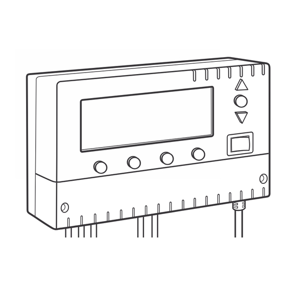
- Page 4 Description of buttons and cable terminals NOTE: In order to access the cable terminals, remove the front cover. SR1 SR2 SR3 OUT1 OUT2 OUT3 OUT4 OUT5 1. Buttons "A, B, C, D" for configuration of individual settings, 2. Terminals for connecting temperature sensors (SR1 through SR3), 3.
- Page 5 Description of the controller working in a CH circuit (part A of the display) 1. CH pump operation indicator, 2. CH pump's sensor indicator, 3. Manual mode operation indicator, 4. Current temperature on the CH sensor (SR1), 5. Set temperature indicator. The controller-pump assembly forces the water to circulate in a CH system with a coal-fired boiler or a gas boiler without a system controlling the operation of the pump.
-
Page 6: Installation
3.1. Installation 3.1.1. Mounting the controller The controller must be mounted on a wall or another support using two screws (the concrete anchors with screws are delivered with the controller). The cables extending from the controller must be fixed to the wall with cable clips. - Page 7 3.2.2. Description of the display The top part of the display (4) shows the current temperature of the sensor while the bottom part (5) shows the set temperature. Movement of the blades on the indicator (1) indicates operation of the CH pump. 3.2.3.
- Page 8 3.2.7. Manual mode - continuous operation In order to manually switch on the circulating pump (regardless of the current temperature at the SR1 (CH) sensor), press the " " button and hold it pressed for 3 seconds. The display will show the hand symbol " "...
- Page 9 6. Indicator of operation of a tee valve or the second CH pump, 7. Indicator of manual activation of a tee valve or the second CH pump. AURATON S14 in a circuit with a boiler stove fireplace uses two control outputs: ź...
- Page 10 4.1. Installation 4.1.1. Mounting the controller The controller must be mounted on a wall or another support using two screws (the concrete anchors with screws are delivered with the controller). The cables extending from the controller must be fixed to the wall with cable clips.
- Page 11 4.2. Operation of the controller 4.2.1. Switching the controller on Set the power supply switch [on/o in the "I" position. After power is switched on, all segments of the display light up. Then the controller indicates the current temperature of measured by the sensor. 4.2.2.
- Page 12 4.2.5. Changing the forced pump operation mode Press the " " button under the temperature setting. The digits begin to blink and indicate the value of the current setting (left indicator). When the " " button is pressed again, the right temperature indicator starts blinking.
-
Page 13: Wiring Diagram
4.3. Wiring diagram An example wiring diagram. This is a simplified diagram that does not contain all the elements necessary for proper operation of the system. SR1 SR2 SR3 OUT1 OUT2 OUT3 OUT4 OUT5 230V mains power supply 1. Boiler stove fireplace, 6. - Page 14 5. I n d i c a t o r o f m a n u a l activation of the pump in the HDW circuit. The AURATON S14 electronic pump controller is also intended for automatic control of the circulation pump (depending on the temperature) in the hot domestic water (HDW) circuit.
- Page 15 5.1.2. Programming of the HDW functions When the " " button is pressed, the value of 50 °C (factory setting) starts blinking. Use the "+" or "-" button to set the desired temperature. Once the desired temperature value is set, it must be confirmed (do not forget to do so) within 10 seconds by pressing the "...
- Page 16 5.2. Operation with the HDW over CH priority switched on If the HDW over CH priority function is switched on, then activation of the pump in the HDW circuit depends not only on the setting and on the temperature measured by the SR3 sensor, which is installed in the HDW tank, but also on the temperature measured by the SR1 (CH) sensor.
- Page 17 5.3.4. Connecting the controller After the wires are secured to prevent accidental ripping, connect the power supply cable on the side of the controller to the IN terminals (L, N). Then connect the cable to a 230V/50 Hz power outlet with a grounding pin.
- Page 18 5.4.5. Switching on the emergency heat takeoff function NOTE: As a default setting, the emergency heat takeoff function is switched off. Be very careful when using this function. The maximum temperature of water in the tank is 85 °C, which may lead to the risk of scalding of people, in particular small children! Press the "...
- Page 19 5.5.2. With the HDW tank SR1 SR2 SR3 230V mains OUT1 OUT2 OUT3 OUT4 OUT5 HDW sensor power supply tank boiler Pump NOTE: When only the SR3 sensor is connected, the remaining functions of the controller are inactive, i.e. there is no indication of operation of CH pump (SR1) and of the control of the CH pump and the tee valve in the fireplace circuit, and the blower is not controlled.
- Page 20 AURATON S14 is a modern processor-based controller intended for work also with forced-draught coal and fine coal fired boilers. Depending on the temperature of water in the boiler, the controller automatically starts or stops the water pump in the CH circuit with a coal- fired boiler and the blower installed under the furnace.
- Page 21 6.2. Operation of the controller 6.2.1. Switching the controller on Set the power supply switch in the "I" position. After power is switched on, all segments of the display light up and the software version is shown for about 2 seconds. Then the controller indicates the current temperature of measured by the SR1 sensor.
- Page 22 AUTO operation mode During normal operation, when the controller attempts to reach the temperature value set in the " " section, the AUTO text is displayed. At that time, the fan is working at full power (programmed as a percentage) until the set value is reached.
- Page 23 6.2.8. Setting the fan's soft start time AURATON S14 enables setting the time within which, after its start, the fan will reach its full power (the percentage value that has been set - see item 6.2.7. Setting the maximum fan power value). It is possible to set the fan's soft start time in the range of 0 seconds (start with the full set power) to 15 seconds, after which the fan reaches its full preset power.
- Page 24 6.2.10. Automatic ignition function symbol displayed in the " " section means that the fan is switched on permanently with the maximum power (programmed as a percentage value) and that simultaneously the circulating pump in the " " section is switched on.
- Page 25 6.3. Explanation of the display's functions the controller displays the "LO" text if the temperature measured by the SR1, SR2, and SR3 sensors drops below 0°C . the controller displays the "EE" text if the temperature measured by the SR1, SR2, and SR3 sensors exceeds 99 °C 6.4.
-
Page 26: Technical Data
RESET In extreme situations (such as crashing of the controller), the RESET function can be used. The RESET button is located under the flap covering the outlet terminals. RESET MASTER RESET This function enables restoring the factory settings. In order to use it, press the "+"... -
Page 27: Cleaning And Maintenance
C. Data pertaining to the controller working with a hot domestic water (HDW) pump Temperature settings range: °C ÷ 85 °C Range of measured values: °C ÷ 99 °C Hysteresis (start stop diff. rom °C to °C Supply voltage: 230V / 50Hz Maximum load for output sum: D. - Page 28 www.auraton.pl...
Need help?
Do you have a question about the S14 and is the answer not in the manual?
Questions and answers