Table of Contents
Advertisement
Advertisement
Table of Contents

Related Manuals for SHOWTEC SC-2412


Summary of Contents for SHOWTEC SC-2412
- Page 1 SC-2412 ORDERCODE 50710...
- Page 2 For more information: iwant@showtec.info You can get some of the best quality, best priced products on the market from Showtec. So next time, turn to Showtec for more great lighting equipment. Always get the best -- with Showtec ! Thank you!
-
Page 3: Table Of Contents
Showtec Showtec SC-2412 Product Guide ™ Warning..…...................…………………………………………....Safety-instructions…………………………………………………………………………………….…...... Operating Determinations……………………………………………………………………………....... Description..…................……….……………………………….…....Features…….……………………………………………………………………………………….……..…....Overview………………………………………………………………………………………………………....Controller front..............................Controller backside............................Installation................…...……………………………………..…....Installation............………………………………………..………........Common Terms...........………………………………………..………........Set Up and Operation..............……..…………………………….…....General Operations................……….…………………………....- Physical fader assignment..........……………………..........- Switching between page A and page B.............………......Entering Program Mode..................………........ -
Page 4: Warning
If your Showtec device fails to work properly, discontinue use immediately. Pack the unit securely (preferably in the original packing material), and return it to your Showtec dealer for service. -
Page 5: Operating Determinations
Repairs, servicing and electric connection must be carried out only by Showtec. For replacement use fuses of same type and rating only. This device falls under protection class I. Therefore it is essential to connect the yellow/green conductor to earth. -
Page 6: Description
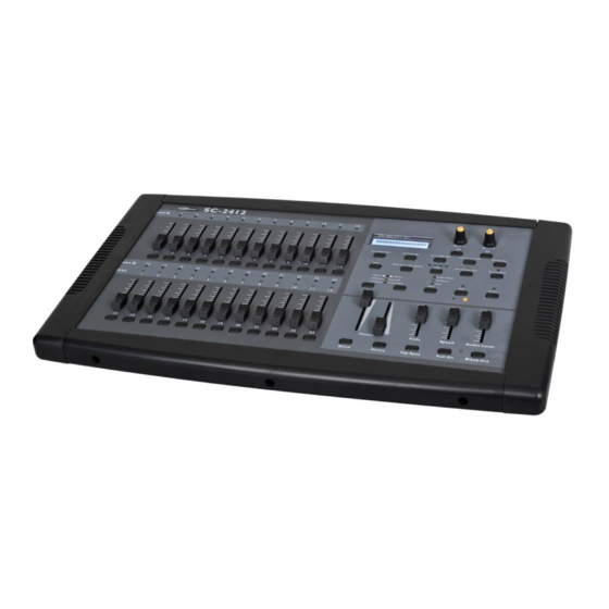
Description of the device The SC-2412 is a universal intelligent lighting controller. It allows the control of 48 channels with 96 scene/chase playback faders. Each scene/chase can contain up to 1000 individual steps, or looks. On the surface, when in the CHASE◄►SCENE mode, there are 12 physical faders for the playback of the saved programs. - Page 7 1) Channel Fader Indicators Indicates channels 1-12(25-36). 2) Channel Fader Used to adjust the intensity of channels 1-12(25-36). 3) Channel Flash button Brings the relevant fader to 100% or DMX value to 255. 4) Channel Fader Indicators Indicates channels 13-24(37-48). 5) Scene Playback indicators Indicates that the playback is active.
-
Page 8: Controller Backside
27) Master A Adjusts overall intensity. 28) Blind Takes the channel out of a program temporarily in Chase ◄► Scene mode. 29) Park Used to select Single/Mix Chase, bring Channel 13-24(37-48) to full of current setting, or momentarily program a scene into Master B slider depending on the current mode. -
Page 9: Installation
Installation Remove all packing materials from the SC2412. Check that all foam and plastic padding is removed. Screw the equipment into a 19" rack. Connect all cables. Always disconnect from electric mains power supply before cleaning or servicing. Damages caused by non-observance are not subject to warranty. Common Terms The following are common terms used in intelligent light programming. -
Page 10: Set Up And Operation
Set Up and Operation Before plugging the unit in, always make sure that the power supply matches the product specification voltage. Do not attempt to operate a 120V specification product on 230V power, or vice versa. 2.1 General Operations 2.1.1 Physical fader assignment Use this feature to combine or unify fixture control attributes for different fixtures. -
Page 11: Entering Program Mode
2.2 Entering Program Mode (record enable) Step Description While holding the record button, tap the flash buttons #1-5-6-8 in sequence. Release the record button. The record LED lights up. 2.2.1 Create a scene Step Description Record enable Select the 1-24 Single mode by tapping the Mode Select button. This will give you control of all 24 channel of the first page. -
Page 12: Erase A Program
2.2.3 Erase a program Step Description Record enable Use the page button to select the page the scene you wish to erase is on. Press and hold the edit button & tap the flash button (13-24) of the scene you wish to erase twice. -
Page 13: Step Operations
Step Operations 2.3.1 Delete a step or steps Step Description Enter the edit mode. Tap the step button to scroll the step you wish to delete. Tap the delete/ rev one button when you reach the step you wish to delete. All the LEDs will light, indicating the deletion of the step. -
Page 14: Playback
2.4 Playback This controller uses the Channel Faders and Channel Flash buttons for multiple uses. In this instance, Channel Faders 13-24 (37-48) are used for the playing back of Scenes already recorded. This is only when the controller is in the Chase◄►Scene mode. In this instance, Master Fader A will control the manual fader controls, while Master Fader B will control the Scenes being played back. -
Page 15: Playing A Scene Using The Speed Fader
2.4.3 Playing a scene using the speed fader Step Description Select your scene as described in the above section. Move the speed fader to show mode position (fully down). Press and hold the rec speed button & tap the corresponding flash button (13-24) The scene tapped will no longer run with the standard beat. -
Page 16: Auxiliary Controls
2.5 Auxiliary controls This is the process of assigning the Auxiliary controls. These will act as shortcuts and are most commonly used for DMX strobe lights or DMX fog machines. However, they are not limited to these functions, such as Pan/tilt control-very useful for remote followspot controls. -
Page 17: Setting Midi Out
MIDI note Function (TURN ON/OFF) 27-69 Turn on or off program 1-48 70-93 Activate channel 1-24 FULL-ON DARK (momentary blackout) HOLD Turn on or off AUDIO MODE: CHASE ◄► SCENE MODE: 1-12A_1-12B MODE: 1-24A Step BLACKOUT Note: When working with MIDI notes 22-93, you may simulate a fader’s increase and decrease by adjusting the velocity of the note. -
Page 18: Sending Midi File Dump
2.6.4 Sending MIDI File Dump Step Description While holding down the record button, simultaneously tap the flash button #3 four times. The display reads MIDI FILEDUMP SENDING 000% when the device is in the correct mode. When holding down record tap the rec exit button to exit the MIDI setting. Notes: This is the process of copying your entire show to another SC2412. -
Page 19: Maintenance
7. Check power from the wall, all cables, the fuse, the settings (return to default), etc. 8. If all of the above appears to be O.K., plug the unit in again. 9. If nothing happens after 30 seconds, unplug the device. 10. Return the device to your Showtec dealer. -
Page 20: Product Specifications
Product Specification Model: Showtec SC2412 Power Adapter : DC 12-18V 500mA Min. DMX-Output: 3-pin female XLR MIDI-Signal: 5-pin standard interface Audio Input: 100 mV~1Vpp. Internal Fuse: F0.5A 250V 5x20 mm Weight : 4,7 kg Design and product specifications are subject to change without prior notice.
Need help?
Do you have a question about the SC-2412 and is the answer not in the manual?
Questions and answers