Table of Contents
Advertisement
Quick Links
Advertisement
Table of Contents

Related Manuals for Extron electronics HDXP 1616


Summary of Contents for Extron electronics HDXP 1616
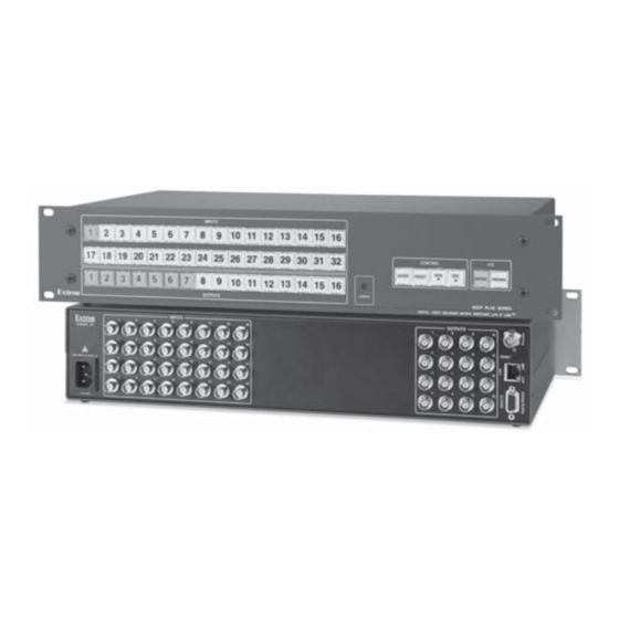
- Page 1 HDXP Plus Series Serial Digital Video Matrix Switchers 68-1200-01 Rev. A 06 06...
- Page 2 Precautions Safety Instructions • English Warning Power sources • This equipment should be operated only from the power source indicated on the product. This This symbol is intended to alert the user of important operating and maintenance equipment is intended to be used with a main power system with a grounded (neutral) conductor. The (servicing) instructions in the literature provided with the equipment.
-
Page 3: Front Panel Controls
Quick Start — HDXP Plus Series Matrix Switchers Installation Step 5 If desired, connect a network WAN or LAN Step 1 hub, a control system, or computer to Turn off power to the input and output devices, the Ethernet RJ-45 port. See chapter 2, and remove the power cords from them. - Page 4 Quick Start — HDXP Plus Series Matrix Switchers, Cont’d Preview button places the HDXP in preview 2. Press and hold an output button until it lights mode, in which one input at a time can be steadily (approximately 2 seconds). selected for viewing.
-
Page 5: Table Of Contents
Table of Contents Chapter One • Introduction ...................... 1-1 About this Manual ........................1-2 About the HDXP Plus Series Matrix Switchers ............1-2 Features ............................1-3 Application Diagrams ......................1-6 Chapter Two • Installation ......................2-1 Mounting the Switcher ......................2-2 Rear Panels and Cabling ...................... - Page 6 Table of Contents, cont’d Locking out the front panel (executive mode) ..............3-25 Setting the button background illumination ..............3-25 Selecting the RS-232/RS-422 protocol and baud rate ............3-26 Resetting ..........................3-27 Resetting using front panel buttons ................3-27 Resetting using the rear panel Reset button ..............3-28 Soft system resets ......................
- Page 7 Sync Time to PC button ..................... 5-11 Setting the offset from GMT .................... 5-11 Enabling daylight savings time ..................5-12 Setting the administrator password ................. 5-12 Setting the user password ....................5-12 Setting the mail server IP address ..................5-13 Setting the mail server domain name ................
- Page 8 Table of Contents, cont’d Set and View Ties Page ......................6-13 Creating a tie ........................... 6-14 Output Settings page ......................6-14 Muting and unmuting the output ................... 6-14 Changing the output re-clocker rate ................6-15 Global Presets page ........................ 6-15 Saving a preset ........................
-
Page 9: Chapter One • Introduction
HDXP Plus Series Matrix Switchers Chapter One Introduction About This Manual About the HDXP Plus Series Matrix Switchers Features Application Diagrams... -
Page 10: About This Manual
-based control software via the RS-232/422 link or an Ethernet connection. The HDXP 1616 and 3216 models are housed in rack-mountable, 2U (3.5") high, full rack metal enclosures. The HDXP 3232 has a 3U (5.25") high, full rack metal enclosure, also rack mountable. Each model has an internal 100 VAC to 240 VAC, 50/60 Hz, 80 watt, autoswitchable power supply that provides worldwide power compatibility. -
Page 11: Features
Features Inputs — 16 or 32 SDI/HD-SDI video inputs on BNC connectors Outputs — 17 or 33 SDI/HD-SDI video outputs (including one preview output) on BNC connectors Serial digital data rates from 143 Mb/s to 2.97 Gb/s — The HDXP switchers can switch signals conforming to all serial digital and high defi... - Page 12 Introduction, cont’d Video Genlock (HDXP 3232 only) — Allows for vertical interval switching, and enables smooth, seamless transitions when switching between synchronous video sources. Separate bi-level (SDI) and tri-level (HD-SDI) references are provided on two additional BNC connectors. Input/output grouping — Allows the matrix to be virtually divided into smaller sub-switchers, making installation and control easier.
- Page 13 • Front Panel Control — The QuickSwitch Front Panel Controller (QS-FPC™) provides a discrete button for each input and each output. An input or output can be selected or switched by a single press of its front panel button. The front panel buttons are large, positive touch, illuminated pushbuttons that can be labeled with text or graphics.
-
Page 14: Application Diagrams
Introduction, cont’d Application Diagrams The following diagrams show examples of HDXP applications. Extron HDXP Plus Series Multi-Rate Digital High Definition Matrix Switcher Digital Media Servers TCP/IP U TS IN PU Remote User and Administration Control SDI/HD-SDI Displays/Monitors Digital Video Tape Recorders SDI/HD-SDI Projectors Figure 1–1 —... -
Page 15: Chapter Two • Installation
HDXP Plus Series Matrix Switchers Chapter Two Installation Mounting the Switcher Rear Panels and Cabling Connections... -
Page 16: Mounting The Switcher
Secure the switcher to the rack using the supplied bolts. The following fi gure shows a diagram of an HDXP 1616 or 3216 being mounted to a standard 19" rack. Figure 2–1 — Rack mounting the HDXP Rear Panels and Cabling Most of the HDXP connectors are on the rear panel. -
Page 17: Connections
INPUTS OUTPUTS RESET Figure 2–3 — HDXP 3216 rear panel GEN-LOCK PREVIEW Figure 2–4 — HDXP 3232 rear panel Connections Use Electrostatic discharge precautions (be electrically grounded) when making connections. Electrostatic discharge (ESD) can damage equipment, although you may not feel, see, or hear it. Remove power from the system before making any connections. -
Page 18: External Sync Connections (Hdxp 3232 Only)
Installation, cont’d External sync connections (HDXP 3232 only) External sync connectors for bi-level and tri-level — Connect an external sync signal to this BNC connector to genlock the video signal in broadcast or other sync-critical applications. The HDXP switchers switch between inputs during the vertical interval period, resulting in glitch-free video switching when the input devices are also using the same sync timing. -
Page 19: Reset Button
Extron SDI/HD-SDI VGA Input VSC 900D Monitor Computer-to-Video Scan Converter (SDI only) Extron HDXP Plus 3232 Extron Matrix Switcher BBG 6 A Blackburst/Color Bars/ Y, Y Audio Generator 0.3A -240 0 Hz 50/6 IE W SDI/HD-SDI SDI/HD-SDI SDI/HD-SDI Video Camera Video Camera Video Camera Figure 2–6 —... -
Page 20: Ethernet Connection
Installation, cont’d Ethernet connection Ethernet port — If desired, connect the HDXP switcher to a PC or to an Ethernet LAN via this RJ-45 connector. You can use a PC to control the networked switcher with SIS commands from anywhere in the world. -
Page 21: Rs-232 And Rs-422 Remote Connections
The cable used depends on your network speed. The switcher supports both 10 Mbps (10Base-T — Ethernet) and 100 Mbps (100Base-T — Fast Ethernet), half-duplex and full-duplex, Ethernet connections. • 10Base-T Ethernet requires CAT 3 UTP or STP cable at minimum. •... -
Page 22: Power
Installation, cont’d 6 feet (1.8 m) Part #70-335-01 Ring Sleeve (Gnd) 9-pin D Connection TRS Plug Pin 2 Computer's RX line Pin 3 Computer's TX line Ring Pin 5 Computer's signal ground Sleeve Figure 3–3 — 2.5 mm connector cable for the confi guration port See chapter 4, Programmer’s Guide, and chapter 5, Matrix Software, for details about using SIS commands and the control software to confi... -
Page 23: Chapter Three • Operation
HDXP Plus Series Matrix Switchers Chapter Three Operation Front Panel Controls and Indicators Front Panel Operations Troubleshooting Confi guration Worksheets... -
Page 24: Front Panel Controls And Indicators
4 5 6 7 Figure 3–1 — HDXP 1616 and HDXP 3216 front panel N On the HDXP 1616, which has only 16 input connectors, the input buttons in the second row (buttons 17 through 32) can be used only for preset selection. -
Page 25: Input And Output Buttons
1 2 3 4 5 6 7 8 9 10 11 12 14 15 16 17 18 19 20 21 22 23 24 25 26 27 28 30 31 32 1 2 3 4 5 6 7 8 9 10 11 12 CONTROL 14 15 16 VIEW... -
Page 26: Control Buttons
Operation, cont’d Control buttons Enter button — The Enter button has three primary functions (•) and fi ve secondary (❏) functions: • Saves changes that you make on the front panel. To create a simple confi guration: Specify a Matrix connection (see I/O buttons [ Press the desired input button ( Press the desired output button(s) ( Press the Enter button. - Page 27 < < button — The View button has two primary functions (•) and View eight secondary (❏) functions: • Places the switcher in view-only mode to display the current confi guration. N View-only mode also provides a way to mute and unmute outputs. See Muting and unmuting outputs, later in this chapter.
-
Page 28: I/O Buttons
Operation, cont’d I/O buttons You must select the input/output connection mode when you are creating or viewing a confi guration. This is done with the Matrix ( ) and Preview ( buttons. Matrix button — The Matrix button has two primary functions (•) and four secondary (❏) functions: •... -
Page 29: Operations
Computer Computer VTG 200 30 31 32 Document Camera Figure 3–4 — Example of button labels on an HDXP front panel section Operations The following sections detail the powering up process and provide procedures for operations that can be performed from the front or rear panel. Powering on Apply power by connecting the power cord to an AC source. -
Page 30: Example 1: Creating A Set Of Ties
Operation, cont’d Press the button for each output that you want to tie to the selected input. • The output buttons blink green when pressed, indicating potential ties. • The Enter button also blinks green. N Outputs that are already tied can remain tied (buttons lit), along with your new blinking selections;... - Page 31 Press and release the Input 5 button. Press and release the Input 5 button. The button lights green. INPUTS 17 18 19 20 21 22 23 24 Figure 3–7 — Selecting input 5 Press and release the Output 3, Output 4, and Output 8 buttons. Press and release the Output 3, Output 4, and Output 8 buttons.
-
Page 32: Example 2: Adding A Tie To A Set Of Ties
Operation, cont’d The confi guration now is: Input 5 tied to output 3, output 4, and output 8 Input 5 Tied to Outputs 3, 4, and 8 Input Output Figure 3–10 — Example 1, fi nal confi guration Example 2: Adding a tie to a set of ties In the following example, a new tie is added to the current confi... - Page 33 Press and release the output 1 button. Press and release the Output 1 button. The button blinks green to indicate that the selected input will be tied to this output. CONTROL VIEW ENTER PRESET OUTPUT The Enter button blinks green to indicate the need to = Blinking button confirm the change.
-
Page 34: Breaking Ties
Operation, cont’d Breaking ties To undo an existing I/O tie, follow these steps: Press the Matrix button. The button lights green. Press the input button whose tie you want to dissolve. The input button and its tied output buttons light green. Press one of the lit output buttons. -
Page 35: Previewing An Input
Press and release the Output 4 button. C O N T R O L The button blinks green to indicate the pending change: output 4 will be untied. VIEW ENTER PRESET The Enter button blinks green to indicate the need to OUTPUT confirm the change. -
Page 36: Viewing The Confi Guration
Operation, cont’d I / O MATRIX PREVIEW Press the Preview button to enter preview mode. The button lights red when selected. Figure 3–23 — Selecting Preview mode N If an input has already been selected in preview mode, its button also lights red when you press Preview. - Page 37 < Press and release the View button. Press the View button to enter view-only mode. CONTROL VIEW ENTER PRESET The button lights red. Figure 3–26 — Entering view-only mode < • The View button lights red. • The Matrix button lights green. •...
-
Page 38: I/O Grouping
Operation, cont’d I/O grouping I/O grouping is a matrix switcher feature that allows you to subdivide the front panel control of the matrix into four smaller functional sub-switchers and limit tie creation from the front panel only. Inputs and outputs can be assigned to one of four groups or not assigned to any group. -
Page 39: Creating I/O Groups
Suggested applications for the I/O grouping feature include: • Segregating specifi c video formats to prevent an input in one video format from being inadvertently applied to an output device that supports another video format (see the illustration below). • Segregating input and output devices that are in separate rooms. - Page 40 Operation, cont’d Inputs Release the Input 1 button and the Output 1 button. Press and hold the 17 18 17 18 Input 1 button and the Output 1 button. 3 Seconds Ungrouped input and output buttons light. Outputs Figure 3–31 — Selecting I/O Group mode Press and release one of the Control buttons to select a group number: •...
-
Page 41: Viewing I/O Groups
• Figure 3-35 on the next page shows the presets associated with the input and output buttons on each HDXP model. (On the HDXP 1616, which has only 16 input connectors, input buttons 17 through 32 are used for presets, but not for input selection.) HDXP Plus Series Switchers •... -
Page 42: Saving A Preset
17 18 19 20 21 22 23 24 25 26 27 28 29 30 31 32 Preset Preset Preset Preset Preset Preset Preset Preset Preset Preset Preset Preset Preset Preset Preset Preset HDXP 3216 and HDXP 1616 Preset Preset Preset Preset Preset Preset Preset Preset Preset Preset Preset Preset Preset Preset Preset Preset... -
Page 43: Recalling A Preset
Press and release the input or output button for the desired preset number. Press and release an input button. The button blinks red to indicate that this C O N T R O L preset number is selected but not saved. VIEW ENTER PRESET... - Page 44 Operation, cont’d (Preset Assigned) Press and release the Preset button. PRESET The Preset button lights. Inputs 17 18 17 18 All input buttons with assigned presets light red. Unlit (No Preset Assigned) Figure 3–41 — Entering Recall Preset mode In the example above, the Input 2 button lights red, because a preset has been assigned to it.
-
Page 45: Muting And Unmuting Outputs
Muting and unmuting outputs You can mute and unmute the outputs on the HDXP using the front panel. (You can also mute/unmute them via SIS commands, the Windows-based control software, and/or the Web pages.) N Mutings are saved to non-volatile memory. When power is removed and restored, the mute settings are retained. -
Page 46: Unmuting An Output
Operation, cont’d < N The front panel times out after 30 seconds, and the View and the blinking output buttons become unlit or return to background lighting. If you want to < mute another output after a timeout, you must press the View button again (repeat steps 2 and 3). -
Page 47: Locking Out The Front Panel (Executive Mode)
Locking out the front panel (executive mode) The front panel security lockout (executive mode) limits the operation of the HDXP from the front panel. When the switcher is locked, all of the front panel functions are disabled except for the view-only mode functions (see Viewing a confi guration, earlier in this chapter). -
Page 48: Selecting The Rs-232/Rs-422 Protocol And Baud Rate
Operation, cont’d Selecting the RS-232/RS-422 protocol and baud rate The HDXP switchers can support either RS-232 or RS-422 serial communication protocol, and operate at 9600, 19200, 38400, and 115200 baud rates. The settings of these variables can be viewed and changed from the front panel. N This information applies to only the rear panel Remote RS232/RS422 port. -
Page 49: Resetting
Press and release the button(s) to configure the port as follows: Baud rate: Enter — 9600 Preset — 19200 < > View — 38400 — 115200 Serial protocol: Matrix — RS-232 Preview — RS-422/RS-485 The selected buttons blink and the others remain lit. In this example, the port is set to RS-422 at 38400 baud. -
Page 50: Resetting Using The Rear Panel Reset Button
Operation, cont’d Press and hold the Matrix and Preview buttons while you apply power to the switcher. I / O MATRIX PREVIEW Power The input and output buttons blink green, red, and amber, then off. Continue to hold the Matrix and Preview buttons until all input and output buttons become unlit and the Matrix button lights green. -
Page 51: Hard Reset
Follow these steps to perform a soft reset of the HDXP from the rear panel: Press and hold in the Reset button until the front panel Matrix and Preview buttons blink once (for events reset), twice (for system reset), or three times (for absolute reset) (fi... -
Page 52: Troubleshooting
Operation, cont’d Troubleshooting This section gives recommendations on what to do if you have problems operating the switcher: Ensure that all devices are plugged in and powered on. The switcher is receiving power if one of the front panel Power Supply LEDs is lit green. Check to see if one or more outputs are muted. -
Page 53: Worksheet Example 2: Daily Confi Guration
Worksheet example 2: Daily confi guration Figure 3-58 continues from worksheet example 1 by showing the video ties that make up the confi guration of preset 1. A solid ink line shows video ties. Input sources Editing Editing SDI/ SDI/ SDI/ Editing VTG 400... -
Page 54: Worksheet Example 3: Test Confi Guration
Operation, cont’d Worksheet example 3: Test confi guration The A/V system in our fi ctional organization needs to be fi ne tuned on a regular basis. Figure 3-59 shows a typical test confi guration, with an Extron video test generator (input 12) generating a test pattern to all monitors (outputs 1, 2, 3, 4, and 8). - Page 55 HDXP Plus Series Switchers • Operation 3-33...
- Page 56 Operation, cont’d HDXP Plus Series Switchers • Operation 3-34...
-
Page 57: Chapter Four • Programmer's Guide
HDXP Plus Series Matrix Switchers Chapter Four Programmer’s Guide RS-232/RS-422 Link Ethernet Link Host-to-Switcher Instructions Switcher-Initiated Messages Switcher Error Responses Using the Command/Response Tables... -
Page 58: Rs-232/Rs-422 Link
Programmer’s Guide Programmer’s Guide, cont’d RS-232/RS-422 Link The HDXP has two connectors that can be used for serial control. Both ports enable use of SIS commands and the Windows-based control software. The default protocol for these ports is as follows: •... -
Page 59: Ethernet Link
Ethernet Link The rear panel Ethernet connector on the switcher can be connected to an Ethernet LAN or WAN. This connection makes SIS control of the switcher possible using a computer connected to the same LAN or WAN. Ethernet connection The Ethernet cable can be terminated as a straight-through cable or a crossover cable and must be properly terminated for your application (see fi... -
Page 60: Default Ip Addresses
The switcher-initiated messages are listed below (underlined). With an RS-232/422 connection: (c) Copyright 2006, Extron Electronics HDXP Plus Series, Vx.xx, 60-XXX-01 With an Internet connection: (c) Copyright 2006, Extron Electronics HDXP Plus Series, Vx.xx, 60-XXX-01 Ddd, DD Mmm YYYY HH:MM:SS The switcher initiates the copyright message when it is fi... -
Page 61: Switcher Error Responses
The switcher initiates the Qik message when a front panel switching or preset recall operation has occurred. Sprnn The switcher initiates the Spr message when a memory preset has been saved from the front panel. “nn” is the preset number. Vmtnn•x The switcher initiates the Vmt message when a video output mute is toggled on or off from the front panel. -
Page 62: Using The Command/Response Table For Sis Commands
HDXP 1616: 0 – 16 HDXP 3216 and 3232: 0 – 32 Input 0 = muted input = Output number HDXP 1616 and 3216: 01 – 16 HDXP 3232: 01 – 32 = Output re-clocking rate 00 = Auto (default) - Page 63 = Room # (for room presets): 0 – 10. (Each room can have up to 10 presets assigned.) A Room is a subset of operator-selected outputs that relate to each other. The HDXP switcher supports up to 10 rooms, each of which can consist of from 1 to 16 outputs per room.
- Page 64 Programmer’s Guide, cont’d = Matrix name (up to 240 characters) The following characters are invalid in the name: ~ , @ [ ] { } ‘ < > “ ” ; \ | and ? = GMT date and time (read) in the format Www,•DD•Mmm•YYYY•HH:MM:SS Www = day of the week (Mon through Sun) DD = day of the month (01 through 31)
- Page 65 = Notifi cation selections HDXP 3216 and 3232: 01 – 32 = Inputs 1 through 32 HDXP 1616: 01 – 16 = Inputs 1 through 16 Power supply: 98 = Notify status for reading (16-digit number). For each digit, 0 = Do not notify...
- Page 66 Programmer’s Guide, cont’d = Event data size b = bit B = byte (8 bits) S = short (16 bits) L = long (32 bits) This parameter is case sensitive. = Event data to write = Number of bytes to read = Event status fi...
-
Page 67: Command/Response Table For Sis Commands
™ Programming and Control, cont’d Command/response table for SIS commands ASCII (Telnet) Response Command Additional description (host to switcher) (switcher to host) Create ties N Commands can be entered back-to-back, with no spaces between commands. Example: 1*1!02*02&003%4*24$. N The HDXP switchers support 1-, 2-, and 3-digit numeric entries. Example: 1*1, 01*01, or 001*001. Tie an input to an output •... - Page 68 Programmer’s Guide, cont’d Command/response table for SIS commands (continued) ASCII (Telnet) Response Command Additional description (host to switcher) (switcher to host) Global presets, continued Directly write global presets ! ... X1! ] Tie input to output as many ties as desired, at the same time saving all ties to preset N A direct write of a global preset should always be preceded by a Clear Global Preset command for that same preset...
- Page 69 (or the fi rst position on the right) is the starting output + 15. The number actually displayed in each position is the input tied to that output. N For the HDXP 1616 and 3216, the starting output number (StO#) should always be 1. Example for HDXP 3232: (See below.)
- Page 70 Programmer’s Guide, cont’d Command/response table for SIS commands (continued) ASCII (Telnet) Response Command Additional description (host to switcher) (switcher to host) View settings, continued View output mutes Each response is the mute status of an output, starting from output 1. n is the maximum number of outputs for the model.
- Page 71 A zero in an input’s position indicates that the input is not in a group. Example (HDXP 1616): See below. Input 1 in group 1 Input 9 not grouped Input 16 in group 2...
- Page 72 Programmer’s Guide, cont’d Command/response table for SIS commands (continued) ASCII (Telnet) Response Command Additional description (host to switcher) (switcher to host) Rooms E X* Write room outputs , ... Y/ ] , ... Assign outputs through to room Example: Outputs 3, 4, 5, and 6 are 8,3,4,5,6MR Mpr8,03,04,05,06 assigned to room 8.
- Page 73 16 video outputs. It has no audio inputs or outputs. Request part number HDXP 3232 = 60-797-01 60-XXX-01 HDXP 3216 = 60-790-01 HDXP 1616 = 60-807-01 X2@ ] Request system status = Power supply voltages and Internal temperature in degrees Fahrenheit.
- Page 74 Programmer’s Guide, cont’d Command/response table for SIS commands (continued) ASCII (Telnet) Response Command Additional description (host to switcher) (switcher to host) Information requests, continued Request system memory usage n bytes used out of n kBytes Show amount of memory used and total available memory for system operations.
- Page 75 Command/response table for SIS commands (continued) ASCII (Telnet) Response Command Additional description (host to switcher) (switcher to host) IP setup commands, continued E X3( X3( ] Set GMT offset Set the Greenwich Mean Time (GMT) offset value ( for the HDXP’s location. GMT offset (-12.00 to +14.0 hours) represents the time difference in hours and...
- Page 76 Programmer’s Guide, cont’d Command/response table for SIS commands (continued) ASCII (Telnet) Response Command Additional description (host to switcher) (switcher to host) IP setup commands, continued E X4^ X1& Confi gure receive timeout X1& X1* ] • Cce X1& = time in 10s of ms to wait for characters coming into port before terminating...
- Page 77 Command/response table for SIS commands (continued) ASCII (Telnet) Response Command Additional description (host to switcher) (switcher to host) IP setup commands, continued E X2& X2& X3* ] Set mail server IP address Set the e-mail domain name X2& and domain name for IP address domain (e.g., extron.com).
- Page 78 . For each input represented by a digit in 0 = do not notify (or no input exists) 1 = notify Example (HDXP 1616): See below. 72EM Notify failed and fixed E-mail input 8 status Ignore input 16 3, 1 1 0 0 0 0 0 1 0 0 0 0 0 0 0 0 1...
- Page 79 Command/response table for SIS commands (continued) ASCII (Telnet) Response Command Additional description (host to switcher) (switcher to host) IP setup commands, continued X1^ ] View whether RAM needs Show dirty RAM status to be saved to fl ash memory 0 = RAM needs to be saved to fl...
- Page 80 Programmer’s Guide, cont’d HDXP Plus Series Switchers • Programmer’s Guide 4-24...
-
Page 81: Chapter Five • Matrix Software
HDXP Plus Series Matrix Switchers Chapter Five Matrix Software Matrix Switchers Control Program Special Characters Button-Label Generator... -
Page 82: Matrix Switchers Control Program
Matrix Software The following software programs accompany the HDXP 3232, 3216, and 1616 switchers: ® • The Windows -based Extron Matrix Switcher Control Program, which communicates with the switcher via the RS-232/RS-422 port and the Ethernet port, provides an easy way to set up ties and sets of ties. •... -
Page 83: Using The Software
To run the Matrix Switcher Control Program, click on the Matrix Switcher + Control Pgm icon (shown at right) in the Extron Electronics group or folder on your Start menu. You can access this icon from your Start menu by selecting the following:... - Page 84 N The following fi gures show the HDXP 3232, which has 32 inputs and 32 outputs. The window for the HDXP 3216 has 32 input boxes and 16 output boxes, while the HDXP 1616’s window has 16 input boxes and 16 output boxes. HDXP Plus Series Matrix Switchers • Matrix Software...
- Page 85 Figure 5–4 — Extron Matrix Switcher Control Program window (no ties or rooms) Figure 5–5 — Sample Matrix window with ties and rooms HDXP Plus Series Matrix Switchers • Matrix Software...
-
Page 86: Setting Up The Matrix Window
Matrix Software, cont’d Setting up the Matrix window On the Matrix window, the inputs and outputs are represented by boxes. You can make the control program easier to use by assigning device icons that represent your connected devices to each input and output box. Click on an input or an output box. -
Page 87: Managing Ties
To change an icon in an input or output box, drag the new icon to the box. It replaces the previous one. To remove the icon from a box and leave the box empty, drag an empty square to the box. Alternatively, you can display the input and output numbers in the boxes instead of icons. -
Page 88: Ip Setup
Matrix Software, cont’d Figure 5–8 — Matrix window section with pop-up information on input 4 IP Setup The IP Settings/Options window (fi gure 5-9) lets you view and, if connected via the RS-232/RS-422 link or if you are logged on via the Ethernet port as an administrator, editing settings unique to the Ethernet interface. -
Page 89: Setting The Ip Address
N Editing the following fi elds on the IP Settings/Options screen while connected via the Ethernet port can immediately disconnect your computer from the switcher: IP Address Gateway IP Address Subnet Mask Use DHCP Administration Password Extron recommends editing the settings on this screen using the RS-232/422 link and protecting the Ethernet access to this screen by assigning an administrator’s password to qualifi... -
Page 90: Setting The Gateway Ip Address
Matrix Software, cont’d Edit the Extron Name/Descriptor fi eld as follows: Click in the Extron Name/Descriptor fi eld. The graphic cursor becomes a text cursor. Edit the name as desired. Press the Tab key on the keyboard or click in another fi eld to exit the Extron Name/Descriptor fi... -
Page 91: Enabling/Disabling Dhcp
Enabling/disabling DHCP Selecting the Use DHCP check box directs the HDXP to ignore any entered IP addresses and to obtain its IP address from a Dynamic Host Confi guration Protocol (DHCP) server (if the network is DHCP capable). Contact the local system administrator for information about DHCP on your system. -
Page 92: Enabling Daylight Savings Time
Matrix Software, cont’d Enabling daylight savings time When daylight savings time is enabled, the switcher updates its internal clock between daylight savings time and standard time in the spring and fall on the date that the time change occurs in your location. When daylight savings time is turned off, the switcher does not adjust its time reference. -
Page 93: Setting The Mail Server Ip Address
Setting the mail server IP address The Mail Server IP Address fi eld displays the IP address of the mail server that handles the e-mail for the facility in which the HDXP switcher is installed. Valid IP addresses consist of four 1-, 2-, or 3-digit numeric subfi elds separated by dots (periods). -
Page 94: Updating The Fi Rmware
Matrix Software, cont’d Press the Tab key on the keyboard or click in another fi eld to exit the e-mail addressee fi eld. Use the check boxes associated with each addressee to select the options about which the addressee will be e-mailed: missing input(s) and/or power supply. When you select either a radio button or a check box for an addressee, the fl... - Page 95 Start the Matrix Switcher Control Program and connect to the HDXP switcher. (See steps 1 through 4 under Using the software, earlier in this chapter, for the procedure.) N The Ethernet connection is much faster than the RS-232/RS-422 connection. Extron recommends using the Ethernet connection rather than the serial port for fi...
-
Page 96: Uploading Html Fi Les
Matrix Software, cont’d Uploading HTML fi les You can create customized HTML pages for the HDXP to display. The HTML Files List window (fi gure 5-13) provides a way to view the contents of the HDXP’s fi le system and to upload custom HTML pages to the switcher. Figure 5–13 —... -
Page 97: Windows Buttons, Menus, And Trash Can
Windows buttons, menus, and trash can The buttons, drop-down menus, and trash can on the right side of the program window perform the following functions: Power — This button is unavailable for HDXP switchers, because the HDXP cannot be powered on and off via software. Executive mode —... -
Page 98: Tools Menu
Matrix Software, cont’d Tools menu The Tools menu contains the following options. (Grayed out options are unavailable on your switcher.) Assign Device Icons — Displays the complete set of input and output device icons. You can drag any of these icons to the input and output boxes. Edit Device Palette —... - Page 99 Hardware status — Provides an overall view of the status of the matrix switcher, including the primary and secondary power supply status and the individual voltages, the internal temperature, the Remote RS-232/RS-422 port confi guration, the number of IP connections, and the installed and updated fi...
-
Page 100: Preferences Menu
Matrix Software, cont’d I/O Group settings — Allows you to establish I/O groups. Drag two or more of the small boxes representing inputs and/or outputs to one of the input or output Group boxes. Repeat as desired. Click Take to establish the group(s). Figure 5–16 —... - Page 101 Ties as Lines — Displays ties as lines (fi gure 5-17). Figure 5–17 — Ties shown as lines Ties as Crosspoints — Displays ties as a matrix of inputs and outputs (fi gure 5-17). Ties that have been made are indicated as amber boxes. Ties that will take effect when you click the Take button are indicated by + in the crosspoint box.
-
Page 102: Master-Reset Selection
Matrix Software, cont’d Frequency-read options — Provides a submenu that allows you to set the input signal detection (DSVP) feature to do one of the following: • Automatically refresh the display (set this option to Automatically every 10 seconds). • Sample the sync and update the display whenever you make a confi... - Page 103 Figure 5–19 — Selecting an emulation fi le N Selecting the Demo.mtx fi le provides a sample of a completed matrix setup. Selecting the New.ini fi le or clicking Cancel provides a blank setup to get you started. On the Save Emulated Matrix Settings window, enter a fi le name under which you want to save any changes to the fi...
-
Page 104: Using The Matrix Switcher Help System
For information about program features, you can access the Matrix Switcher Help program in any of the following ways: • From the Extron Electronics program folder or Start menu group, select the MATRIX Switcher+ Help icon (shown at right). •... -
Page 105: Using The Button Label Generator
By default, the Windows installation goes in either the C:\Program Files\Extron\ ButtonLabelGenerator directory. The Button Label Generator icon is placed in the “Extron Electronics” group or folder. To run the Button Label Generator program, double-click on the Button Label Generator icon (shown at right) in the Extron Electronics group or folder. - Page 106 Matrix Software, cont’d Edit the selected button by using any of the tools provided on the Button Label Generator window. Some of the edits you can make are: • Enter text, and select the font, text size, and text color from the drop- down menus on the tool bar.
-
Page 107: Chapter Six • Html Operation
HDXP Plus Series Matrix Switchers Chapter Six HTML Operation Accessing the Web Pages System Status Page System Settings Page Using the File Management Page Set and View Ties Page Special Characters... -
Page 108: Accessing The Web Pages
HTML Operation The HDXP can be controlled and operated through its Ethernet port, connected via a LAN or WAN, using a web browser such as Microsoft’s Internet Explorer. The browser displays the switcher’s Web pages, which provide an alternative means of viewing and operating the HDXP. -
Page 109: System Status Page
In the Password fi eld, enter the appropriate administrator or user password. If desired, select the check box to have the system input your password the next time you enter your HDXP’s IP address. Click OK. N A User Name entry is not required. The HDXP switcher checks several possibilities, in the following order, and then responds accordingly: •... -
Page 110: Dsvp Page
HTML Operation, cont’d DSVP page You can view a snapshot-in-time of the input frequencies of connected inputs on the Digital Sync Validation Processing (DSVP) page (fi gure 6-3). Click the DSVP link on the sidebar menu to the left of the Status page to display the DSVP page. Figure 6–3 —... -
Page 111: Ip Settings Fi Elds
On password-protected connections, there are two levels of protection: administrator and user. Administrators have full access to all switching capabilities and editing functions. Users can create ties, create and recall presets, and view all settings with the exception of passwords. •... -
Page 112: Mac Address Fi Eld
HTML Operation, cont’d MAC Address fi eld The Media Access Control (MAC) Address is hard coded in the switcher and cannot be changed. Date/Time Settings fi elds The Date/Time Settings fi elds (fi gure 6-5) provide a location for viewing and setting the time functions. -
Page 113: Passwords Page
Passwords page Access the Passwords page (fi gure 6-6) by clicking the Passwords link on the sidebar menu on System Settings page. Figure 6–6 — Passwords page The fi elds on the Passwords page are for entering and verifying administrator and user passwords. -
Page 114: Email Settings Page
HTML Operation, cont’d Email Settings page Access the Email Settings page (fi gure 6-7) by clicking the Email Settings link on the sidebar menu on the System Confi guration page. The Email Settings page has fi elds for setting up the HDXP’s e-mail notifi cation capabilities. For the e-mail settings and for each row of the e-mail notifi... -
Page 115: Smtp Authorization Required Fi Elds
SMTP Authorization Required fi elds Selecting the SMTP Authorization Required check box sets the HDXP to require SMTP authorization before accepting any e-mail. To set up this authorization requirement, follow these steps: To enable the SMTP authorization fi elds, click the Edit button at the right of the Mail IP Address fi... -
Page 116: Firmware Upgrade Page
HTML Operation, cont’d Firmware Upgrade page The Firmware Upgrade page provides a way to replace the fi rmware that is coded on the HDXP’s control board without needing to take the switcher out of service. Access the Firmware Upgrade page (fi gure 6-9) by clicking the Firmware Upgrade link on the System Confi... - Page 117 Click the Browse button. A Choose fi le window opens. Navigate to the folder where you saved the fi rmware upgrade fi le. Select the fi le. Figure 6–10 — Choose fi le window with a fi rmware fi le selected N Valid fi...
-
Page 118: Using The File Management Page
HTML Operation, cont’d Using the File Management Page To delete fi les (such as HTML pages) from the switcher or to upload your own fi les to the switcher, click the File Management tab. The switcher displays the fi le management HTML page (fi... -
Page 119: Other Fi Le Management Activities
To add more fi les to the directory, click the directory name to open it, then use the Uploading fi les procedure. To exit the directory, click (root) or (back). Other fi le management activities You can also perform the following tasks on the File Management screen: Open a fi... -
Page 120: Creating A Tie
HTML Operation, cont’d Creating a tie Select and switch an input as follows: Move the mouse over the matrix of input and output selection buttons. Click on a button to create a preliminary tie of the input and output associated with that button (if they are not already tied) or a preliminary untie (if the input and output are tied) . -
Page 121: Changing The Output Re-Clocker Rate
Changing the output re-clocker rate To change the output re-clocker rate, do the following: Select the desired output from the pull-down menu. From the Re-Clocker Rate pull-down menu, select the desired rate. • Select Automatic if you want the re-clocker to automatically adapt the output to the input signal. -
Page 122: Recalling A Preset
HTML Operation, cont’d Click the Accept button. If you do not rename an unassigned button, the HDXP names the preset as Preset nn (nn is the next available number). If you do not rename an existing preset when it is overwritten, the HDXP retains the same name. -
Page 123: Ethernet Link
HDXP Plus Series Matrix Switchers A ppendix A Ethernet Connection Ethernet Link Subnetting — A Primer... -
Page 124: Default Address
Ethernet Connection Ethernet Link The rear panel Ethernet connector on the HDXP switcher can be connected to an Ethernet LAN or WAN. This connection makes SIS control of the switcher possible using a computer connected to the same LAN. Ethernet connection The Ethernet cable can be terminated as a straight-through cable or a crossover cable and must be properly terminated for your application (fi... -
Page 125: Ping To Determine Extron Ip Address
Ping to determine Extron IP address The Microsoft Ping utility is available at the DOS prompt. Ping tests the Ethernet interface between the computer and the HDXP switcher. Ping can also be used to determine the actual numeric IP address from an alias and to determine the web address. -
Page 126: Telnet Tips
Ethernet Connection, cont’d Microsoft (R) windows 2000 (TM) Version 5.0 (Build 2195) Welcome to Microsoft Telnet Client Telnet Client Build 5.00.99203.1 Escape Character is 'CTRL+]' Microsoft Telnet> Figure A–3 — Telnet screen Telnet tips It is not the intention of this manual to detail all of the operations and functionality of Telnet;... -
Page 127: Local Echo
Local echo Once your computer is connected to the HDXP switcher, by default Telnet does not display your keystrokes on the screen. SIS commands are entered blindly, and only the SIS responses are displayed on the screen. To command Telnet to show all keystrokes, enter set local_echo at the Telnet prompt before you open the connection to the switcher. -
Page 128: Local And Remote Devices
Ethernet Connection, cont’d Local and remote devices The local and remote devices are defi ned from the point of view of the function being described. In this manual, subnetting is an issue when you are using the controlling PC to set TCP/IP and e-mail values in the HDXP switcher (see IP Settings/Options window in chapter 5, Matrix Software, and Email Settings page in chapter 6, HTML Operation). - Page 129 If the unmasked octets of the two IP addresses match (indicated by = in fi gure A-6, example 1), the two addresses are on the same subnet. If the two unmasked fi elds do not match (indicated by an unequal sign in fi...
- Page 130 Ethernet Connection, cont’d HDXP Plus Series Matrix Switchers • Ethernet Connection...
-
Page 131: Appendix B • Reference Information
HDXP Plus Series Matrix Switchers A ppendix B Reference Information Specifi cations — HDXP Plus Series Part Numbers and Accessories Button Labels... - Page 132 Reference Information Specifi cations Video Routing 1616 Series ......16 x 17 matrix 3216 Series ......32 x 17 matrix 3232 Series ......32 x 33 matrix Gain ..........Unity Data rates ........19 Mbps to 2.970 Gbps Auto data rate lock ......Yes Standard .........
- Page 133 Control/remote — switcher Serial control ports ......1 RS-232 or RS-422, 9-pin female D connector 1 RS-232 front panel 2.5 mm mini stereo jack Baud rate and protocol ....9600 (default), 19200, 38400, 115200 baud (adjustable); 8 data bits, 1 stop bit, no parity Serial control pin confi...
-
Page 134: Included Parts
Reference Information, cont’d Part Numbers and Accessories Included parts Replacement part Included part number HDXP 1616 60-807-01 HDXP 3216 60-790-01 HDXP 3232 60-797-01 US style IEC power cord Rubber feet, self-adhesive HDXP Plus Series Matrix Switchers User’s Manual Tweeker (small screwdriver) -
Page 135: Button Labels
Button Labels Page B-7 provides strips of blank button labels. If desired, photocopy them or cut them out of the manual, write button information in each button area as desired, and put them in the switcher’s input or output buttons’ windows. You can also create labels using the Button-Label Generator software (see chapter 5, Matrix Software). - Page 136 Reference Information, cont’d Insert one of the new label you created in step 1 into the clear button cap, align the white backing plate with the cap, and fi rmly snap it into place. Gently, but fi rmly, press the reassembled button into place on the HDXP front panel.
- Page 137 HDXP Plus Series Matrix Switchers • Reference Information...
- Page 138 Reference Information, cont’d HDXP Plus Series Matrix Switchers • Reference Information...
- Page 139 Extron’s Warranty Extron Electronics warrants this product against defects in materials and workmanship for a period of three years from the date of purchase. In the event of malfunction during the warranty period...
- Page 140 Beeldschermweg 6C 16 Ichibancho Anaheim, CA 92805 3821 AH Amersfoort PM Industrial Building Chiyoda-ku, Tokyo 102-0082 Japan The Netherlands Singapore 368363 +81.3.3511.7655 714.491.1500 +31.33.453.4040 +65.6383.4400 Fax +81.3.3511.7656 www.extron.com Fax 714.491.1517 Fax +31.33.453.4050 Fax +65.6383.4664 © 2006 Extron Electronics. All rights reserved.
Need help?
Do you have a question about the HDXP 1616 and is the answer not in the manual?
Questions and answers