Table of Contents
Advertisement
Installation Data
Installation Man u al
TM
ePump
Variable
Speed Pump
User Interface
FOR YOUR SAFETY - This product must be installed and serviced by a pro fes sion al pool/spa service
technician. The procedures in this manual must be followed ex act ly. Failure to follow warning notices
and instructions may result in property damage, serious injury, or death. Improper installation and/or
operation will void the warranty.
WARNING
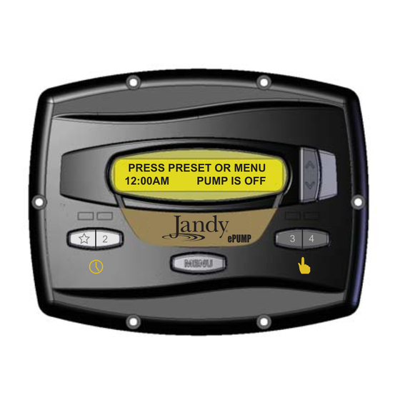
PRESS PRESET OR MENU
12:00AM
PUMP IS OFF
2
ePUMP
3
4
Advertisement
Table of Contents

Related Manuals for Jandy ePump


Summary of Contents for Jandy ePump
- Page 1 Installation Data Installation Man u al ePump Variable Speed Pump User Interface PRESS PRESET OR MENU 12:00AM PUMP IS OFF ePUMP WARNING FOR YOUR SAFETY - This product must be installed and serviced by a pro fes sion al pool/spa service technician.
-
Page 3: Table Of Contents
Section 6. Menu Flow Chart ......15 Connection to the Jandy ePump Variable Speed Pump ............7 Jandy ePump™ Variable Speed Pump Switch Settings ............... 7 Connection to Remote Contacts ......8 Remote Operation ..........8 2.10 Remote Closure 4 Behavior ........ 8 Section 3. -
Page 4: Section 1. Important Safety Instructions
Page 4 Important Safety Instructions Section 1. READ AND FOLLOW ALL INSTRUCTIONS LIRE LA NOTICE TECHNIQUE. All electrical work must be performed by a licensed electrician and conform to all national, state, and local codes. When installing and using this electrical equipment, basic safety precautions should always be followed, including the following: DANGER To reduce the risk of injury, do not remove the suction fittings of your spa or hot tub. -
Page 5: Save These Instructions
Page 5 WARNING People with infectious diseases should not use a spa or hot tub. To avoid injury, exercise care when entering or exiting the spa or hot tub. Do not use drugs or alcohol before or during the use of a spa or hot tub to avoid unconsciousness and possible drowning. Pregnant or possibly pregnant women should consult a physician before using a spa or hot tub. -
Page 6: Section 2. Installation Of The User Interface
LCD Display Arrow Keys LED Lights WARNING ELECTRICAL SHOCK HAZARD Turn off all switches and the main breaker in the ePump™ PRESS PRESET OR MENU electrical circuit before starting the procedure. Failure to 12:00AM PUMP IS OFF comply may cause a shock hazard resulting in severe personal injury or death. -
Page 7: Installation Of The Backplate On A Flat Wall
4-Position WARNING DIP Switch ELECTRICAL SHOCK HAZARD Turn off all switches and the main breaker in the ePump™ RS485 Cable electrical circuit before starting the procedure. Failure to comply may cause a shock hazard resulting in severe personal injury or death. -
Page 8: Connection To Remote Contacts
Turn off all switches and the main breaker that supplies power to the ePump™. WARNING ELECTRICAL SHOCK HAZARD Turn off all switches and the main breaker in the ePump™ REMOTE ENABLED electrical circuit before starting the procedure. Failure to 10:00AM... -
Page 9: Section 3. User Operation
œ "4", press button " " through "4" corresponding to the pump shuts down, the ePump™ will continue to run desired speed. The associated LED will light red and the for 30 minutes, and the ePump™ Controller will controller enters the RUN mode. -
Page 10: Timeclock Setup And Operation
NOTE Pump speed is adjustable only within a certain range. The minimum and maximum limits of the range are set by the installer. 2:PRESET 2 TIMECLOCK ENABLE ePUMP MENU Ÿ 2:PRESET 2 10:00AM RPM: 1400 ePUMP MENU 3.5.2... -
Page 11: Section 4. Service Setup Options
A clock icon appears controller, and create the range of allowable speed that may on the display when the timer has assumed control of the off be sent to the ePump™. time. To set the minimum speed, from the service setup menu, select SET MIN LIMIT using the arrow keys. -
Page 12: Last Fault
MENU Pump Freeze Protect Operation When enabled to do so, the ePump™ controller monitors the temperature inside the pump and will activate the ePump™ at the eStar speed when the temperature approaches freezing. To set priming speed, select PRIMING SPEED using the The run duration of the pump freeze protect operation is arrow keys. -
Page 13: Selecting Pump Type
Pressing the key " " once overrides the pump freeze protect The ePump™ controller comes from the factory with pre- run time, pressing it twice turns off the pump. Pressing other programmed labels or names for the preset speeds. The labels preset keys will override the pump freeze protect run time and may be changed as desired to suit your particular installation. -
Page 14: General Labels
Preset. Press MENU to assign the label to the Preset. SELECT USER SETUP DISPLAY LIGHT LABEL PRESET FILTRATION ePUMP MENU ePUMP MENU Language Selection From the setup menu, select LANGUAGE using the arrow keys. Press MENU. Using the arrow keys, select the desired Custom Labels language. -
Page 15: Section 6. Menu Flow Chart
SET ESTAR I: 10 PUMP SPEED TYPE SET TO [1750]RPM NOTES [ePUMP] R: MIN TO MAX I: 10RPM Default parameters are shown in [ ]. VSP AC “R” stands for Range. “I” stands for Increment. 1. Accessed directly by front panel button. -
Page 16: Limited Warranty
If the dealer is not available, you can locate a service center in your area by visiting www.jandy.com or by calling our technical support department at 1.800.822.7933. All returned parts must have a Returned Material Authorization number to be evaluated under the terms of this warranty.
Need help?
Do you have a question about the ePump and is the answer not in the manual?
Questions and answers