Table of Contents
Advertisement
Quick Links
POWER
D604
PROFESSIONAL POWER AMPLIFIER
Owner's Manual
10
10
11
9
11
9
12
8
12
8
13
7
13
7
PROTECT
15
6
15
6
17
5
17
5
CLIP
19
4
19
4
22
3
22
3
29
2
29
2
SIGNAL
54
1
54
1
0
0
CHANNEL 1
CHANNEL 2
D604
10
10
11
9
11
9
12
8
12
8
13
7
13
7
PROTECT
15
6
15
6
17
5
17
5
CLIP
19
4
19
4
22
3
22
3
29
2
29
2
SIGNAL
54
1
54
1
0
0
CHANNEL 3
CHANNEL 4
Advertisement
Table of Contents

Related Manuals for HPA D604


Summary of Contents for HPA D604
- Page 1 Owner’s Manual D604 POWER D604 PROTECT PROTECT CLIP CLIP PROFESSIONAL POWER AMPLIFIER SIGNAL SIGNAL CHANNEL 1 CHANNEL 2 CHANNEL 3 CHANNEL 4...
- Page 2 WARNING...
-
Page 3: Table Of Contents
Table of Contents D604 Table of Contents Introduction ………………………………………………………… 2 Front Panel Controls ………………………………………………… 3 Rear Panel Controls ………………………………………………… 4 Connections …………………………………..……………… 5 Wiring ..................7 Block Diagrams ……………………………………………..……… 8 Specifications …………………………………………………….… 9... -
Page 4: Introduction
CHANNEL 4 D604 Welcome This section briefly describes the possibilities of the HPA D604 Class-D Power Ampli- fiers. The D series amplifiers are digital power amplifiers designed to meet the specialized needs of sound contractors. They are designed in six different models of Class D power amplifiers, divided in three different architectures to meet the requirements for all kinds of applications. -
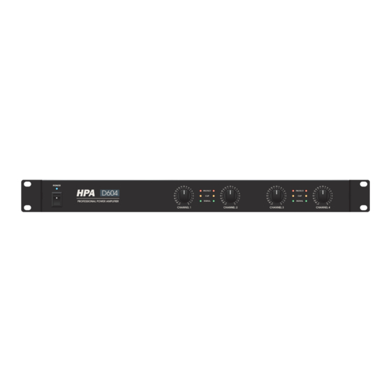
Page 5: Front Panel Controls
D604 Front Panel Controls Front Panel Controls POWER D604 PROTECT PROTECT CLIP CLIP PROFESSIONAL POWER AMPLIFIER SIGNAL SIGNAL CHANNEL 1 CHANNEL 2 CHANNEL 3 CHANNEL 4 1. Power switch: By means of the power switch, the amplifier can be turned ON and OFF. When the amplifier is switched on, the blue LED located above the power button will illuminate. -
Page 6: Rear Panel Controls
Rear Panel Controls D604 Rear Panel Controls OUTPUT BALANCED BALANCED INPUT INPUT CH 3 CH 1 BRIDGE BRIDGE BRIDGE PARALLEL BRIDGE PARALLEL CH 4 CH 3 CH 2 CH 1 CH 4 CH 2 CONNECT 2 CONNECT 1 STEREO STEREO 1. -
Page 7: Connections
Connections D604 Binding posts connectionS 1) Stereo Mode: OUTPUT BALANCED BALANCED INPUT INPUT CH 3 CH 1 BRIDGE BRIDGE BRIDGE PARALLEL BRIDGE PARALLEL CH 4 CH 3 CH 2 CH 1 CH 4 CH 2 CONNECT 2 CONNECT 1 STEREO... - Page 8 Connections D604 Speakon connections 1) Stereo Mode: OUTPUT BALANCED BALANCED INPUT INPUT CH 3 CH 1 BRIDGE BRIDGE BRIDGE PARALLEL BRIDGE PARALLEL CH 4 CH 3 CH 2 CH 1 CH 4 CH 2 STEREO STEREO CONNECT 2 CONNECT 1...
-
Page 9: Wiring
Wiring D604 Wiring These are several ways to interface the D 604 amplifier to support a variety of applica- tions. The D 604 features balanced inputs and outputs; so connecting balanced and unbalanced signals is possible. Unbalances 1/4” Connector Speakon® Output Connector Balances TRS 1/4”... -
Page 10: Block Diagrams
D604 Block diagrams Block diagrams... -
Page 11: Specifications
Specifications D604 Specifications D604 Satellite Stereo@8 Ohm 4 x 80 Watt Rated Power Satellite Stereo@4 Ohm 4 x 150 Watt (1 kHz, THD 1%) Satellite Bridge@8 Ohm 2 x 300 Watt input Sensitivity (Impedance 20 kOhm) +4 dBu Frequency response (± 1dB)
Need help?
Do you have a question about the D604 and is the answer not in the manual?
Questions and answers