Advertisement
Technical
Manual
Table of Contents
Specification.....................................1
Parts List ..........................................2~5
Destination Setting...........................6
Wiring Diagram ...............................7
PCB Assembly .................................8
Schematic Diagram..........................9
Specification
Power Configurations
Watts/Channel
Total Harmonic Distortion (20Hz-20kHz, 8 ohms)
Continuous Rated Power
One-Half Rated Power
One Watt per Channel
Power Output (4 Ohms, 0.09% THD)
Output Peak Current
Intermodulation Distortion 60 Hz:7 kHz, 4:1
Damping Factor (8 ohms)
Amp Gain
Input Sensitivity/Impedance
Frequency Response
Signal to Noise Ratio (IHF A)
Power Requirements
USA
Europe
Power Consumption
Dimensions (W x H x D)
Panel Height (for rack mounting)
Weight (net)
10-10 SHINSEN-CHO , SHIBUYA-KU,
TOKYO 150-0045, JAPAN
Quality Uncompromised
RB-1092/v02
2 x 500 Watts
500 watts, all channels driven, with 20KHz filter,
8 ohm load, 20-20 kHz, 0.03% THD
< 0.03%
< 0.03%
< 0.03%
1000 watts
40A
< 0.03%
400
27.2dB
2.2 V / 11.1 k ohms
10 - 40 KHz (±3dB)
118 dB
120 Volts, 60 Hz
230 Volts, 50 Hz
600 Watts
69 Watts - Idling
3 Watts - Standby
432 x 92 x 407 mm
17
/
x 3
/
x 16
1
5
8
8
80 mm, 3
1
/
in
8
10 kg, 22 lb.
®
STEREO POWER AMPLIFIER
/
in
1
8
Serial. NO.
Y-388A-0610/pdf
Advertisement
Table of Contents

Related Manuals for Rotel RB-1092/v02


Summary of Contents for Rotel RB-1092/v02
-
Page 1: Table Of Contents
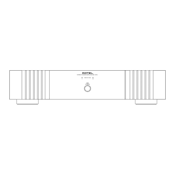
Quality Uncompromised ® Technical STEREO POWER AMPLIFIER RB-1092/v02 Manual Table of Contents Specification........1 Parts List ..........2~5 Destination Setting......6 Wiring Diagram .......7 PCB Assembly .........8 Schematic Diagram......9 Specification Power Configurations 2 x 500 Watts Watts/Channel 500 watts, all channels driven, with 20KHz filter, 8 ohm load, 20-20 kHz, 0.03% THD... - Page 2 RB-1092v02 Appearance STEREO POWER AMPLIFIER RB-1092 PROTECTION POWER Please be requested: When the fault are in the 1000ASP module, replace the module and send back the modules later. History to RB-1092v02 from RB-1092: AC Line is replaced with three conductors from two conductors.
-
Page 3: Parts List 1/2
RB-1092 Parts List 1/2 SYMBOL PARTS NO. DESCRIPTION 016 X-1438A01-02 PCB ASSY 501 X-1438-C PCB ASSY 013 4TTU-13 PCB SUPPORT T101 022 T-1075NO2 SUB TRANSFORMER IC101 031 PC817X2 IC (PHOTO COUPLER) PC817X2J000F Q101 032 TC3708-ST TRANSISTOR 2SC3708AA-ST D102,103,104,106,107 034 T1N4148-86 DIODE 1N4148TAP-50 D105 034 TRD12JST1... -
Page 4: Parts List
RB-1092 Parts List 2/2 SYMBOL PARTS NO. DESCRIPTION 072 4TR-2489 3.5mm PLUG SHIELD CORD 072 C-4621A03 AC CORD SET (SJT AWG16) for RAA (RB-1092) 072 C-4392A04 AC CORD SET (SJT AWG14) for RAA (RB-1091v02) 072 C-4622A02 AC CORD SET for AUSTRALIA (RB-1092) 072 C-4423A04 AC CORD SET for AUSTRALIA (RB-1092v02) 072 C-4624A03... - Page 5 Addendum List for Black and Silver RB-1092 SYMBOL PARTS DESCRIPTION 011 FP-590-B BLACK PANEL ASSY 011 FP-590-S SILVER PANEL ASSY 011 VP3-01A00 H/S PANEL H150 013 VP3-03A00 SUB PANEL HOLDER (BLK) 013 VP3-03A01 SUB PANEL HOLDER (SLV) 012 RV4-09A00 PUSH BUTTON 14F (BLK) 012 RV4-09A01 PUSH BUTTON 14F (SLV) 034 SEL1124R...
-
Page 6: Destination Setting
RB-1092 Destination setting 1. find the FUSE in the 092 ICEPOWER1000ASP. 2. Set the Fuse to the destination country voltage on the PCB. 3. Replace the fuse value to the destination. 5HT10-R for 115V and 5HT6.3 for 230V on both PCB's. 4. -
Page 7: Wiring Diagram
RB-1092v02 Wiring Diagram Wiring-1 CNT ASSY PCB,etc 1000ASP X-1445-01 X-1438-01 068 C-4897A01 K205 PIN JACK (L) L (P2) (9P-2P3P 120mm) 068 C-4897A01 K206 PIN JACK (R) R (P2) (9P-2P3P 120mm) 068 C-4896A01 X-1445-01 (K201) L (P4) (4P 160mm) 068 C-4896A01 R (P4) X-1445-01 (K202) (4P 160mm) -
Page 8: Pcb Assembly
RB-1092 PCB Assembly 016 X-1445A01 - 03 Output and Protection PCB 016X-1445A01 K209 L201 L202 K204 RY201 RY202 K201 K203 K202 S901 016X-1445A03 Sub Transformer PCB 016 X-1438A01 -02... -
Page 9: Schematic Diagram
RB-1092v02 Schematic Diagram FUSE FUSE C30B...
Need help?
Do you have a question about the RB-1092/v02 and is the answer not in the manual?
Questions and answers