Table of Contents
Advertisement
Quick Links
Thank you for choosing a GREE air conditioner. Please read this owner's manual
carefully before operating the unit and keep it handy for future reference.
WWW.GREE.CA
St-Mathieu-de-Beloeil (Québec) Canada
1-866-680-GREE
00510-14/07/11
Please read this manual carefully before running the unit.
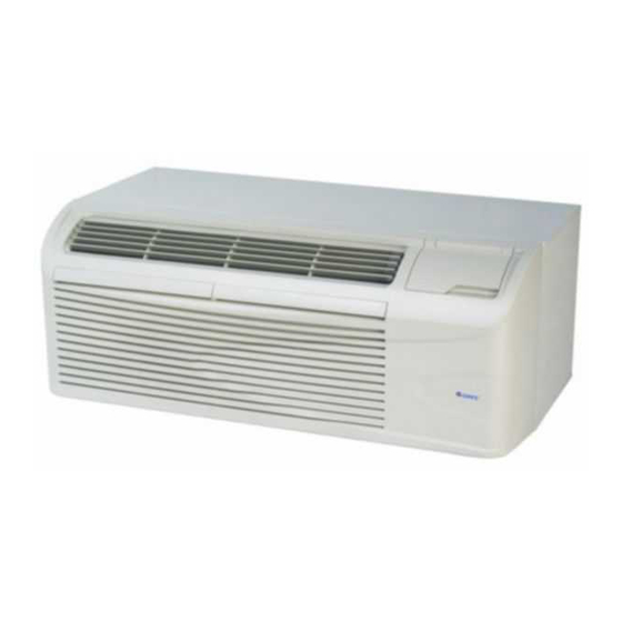
PACKAGED TERMINAL
AIR CONDITIONER
OWNER'S MANUAL
MODELS:
13-04690 / GAE09AB-D3RNB1A
13-04704 / GAA09AB-D3RNB1A
13-04691 / GAE12AB-D3RNB1A
13-04705 / GAA12AB-D3RNB1A
13-04692 / GAE15AB-D3RNB1A
13-04706 / GAA15AB-D3RNB1A
© Copyright, Sunrise Tradex Corp., 2011
Advertisement
Table of Contents

Related Manuals for Gree GAE09AB-D3RNB1A


Summary of Contents for Gree GAE09AB-D3RNB1A
- Page 1 13-04691 / GAE12AB-D3RNB1A 13-04705 / GAA12AB-D3RNB1A 13-04692 / GAE15AB-D3RNB1A 13-04706 / GAA15AB-D3RNB1A Thank you for choosing a GREE air conditioner. Please read this owner's manual carefully before operating the unit and keep it handy for future reference. WWW.GREE.CA St-Mathieu-de-Beloeil (Québec) Canada...
-
Page 2: Table Of Contents
CONTENTS 1. SAFETY CONSIDERATIONS ...................... 1 2. GENERAL INFORMATION ......................1 3. UNIT FEATURES ........................2 4. ELECTRICAL DATA ........................ 4 5. INSTALLATION ........................5 6. HOW TO CONNECT ........................ 8 7. SYSTEM CONFIGURATION ...................... 9 8. AUXILIARY CONTROLS ......................12 9. -
Page 3: Safety Considerations
NOTE: We strongly recommend that any servicing be performed by a qualified individual. GENERAL INFORMATION GREE packaged terminal air conditioners and heat pumps provide high quality performance, workmanship, durability and appearance, as they heat and cool the living space year round. This manual provides information for installation, operation and maintenance. -
Page 4: Unit Features
UNIT FEATURES This premium unit has many exciting features that differ from those of most standard PTAC models. The owner must be familiar with these features in order to fully understand the operation and capability of the unit. • Intelligence – Your premium unit has a computer that utilizes real-time diagnostics to prolong the life of your unit. - Page 5 UNIT FEATURES CONTINUED • Unit configuration – There are many different possible configurations, set with both DIP switches and the digital keypad, that allow you to configure the unit for your exact needs. See the section on unit configuration for more details. The following are the configuration selections that have not previously been mentioned: •...
-
Page 6: Electrical Data
ELECTRICAL DATA WARNING ELECTRICAL SHOCK HAZARD Failure to follow this warning could result in personal injury or death and/or property damage. DO NOT alter cord or plug. DO NOT use an extension cord. • POWER CONNECTION OPTIONS The appropriate power cord accessory kit is determined by the voltage and amperage of the branch circuit. The unit does not come with a power cord (or hard wire kit). -
Page 7: Installation
Units are shipped without a sleeve. In applications where unit is a replacement, it is recommended that a GREE or Carrier sleeve be used. These units can retrofit General Electric, Amana, Trane, and Friedrich sleeves/grills (be sure outdoor grill is installed on the sleeve). -
Page 8: Electrical Shock Hazard
Carrier sleeve is used with an existing non-GREE grill. Use of a GREE or Carrier wall sleeve with a non-GREE grill requires the installation of a baffle accessory kit (see Fig. 8), which ensures a good seal between the unit and the exterior grill to prevent air recirculation. Air recirculation is a large contributor to performance loss and premature damage to major components. -
Page 9: Install Unit Into Wall Sleeve
• INSTALL UNIT INTO WALL SLEEVE 1. Carefully remove the shipping tape from the front panel and vent door. See Fig. 9. 2. Remove the shipping screw from the vent door, if present. See Fig. 10. 3. Remove the front panel. See Fig. 11. 4. -
Page 10: How To Connect
Fig. 15 – Power connection Junction box cover Junction box Table 4—POWER CONNECTION CHART Fig. 14 – Junction box location CODE OF POWER SUPPLY KIT UNIT MODEL 230/208 VOLT GAE09AB-D3RNB1A N/A* GAA09AB-D3RNB1A PWRCORD- PWRCORD- 230V - 20A 230V - 15A GAE12AB-D3RNB1A... -
Page 11: System Configuration
SYSTEM CONFIGURATION • VENTILATION CONTROL • The ventilation control lever is located on the left side of the unit, behind the front panel. Vent control NOTE: The vent door shipping hardware must be removed before (Pull lever through Open using the vent control lever. See Installation Instructions. label to operate.) •... -
Page 12: Dip Switches
• DIP SWITCHES • Auxiliary DIP switch controls are located behind the front panel, through an opening below the control panel. To access, remove the front panel. See Fig. 11. • DIP switches are accessible without opening the control box. The unit must be OFF to effectively change their status. -
Page 13: Keypad Configuration
• KEYPAD CONFIGURATION Keypad configuration Allows further configuration of system to desired application. Changes do not take effect until power to the unit is turned on. To enter keypad configuration Turn on the unit. Press and hold the Fan Speed button and the COOLER button for 5 continuous seconds, within 30 seconds of the unit being turned on. -
Page 14: Auxiliary Controls
AUXILIARY CONTROLS • WALL THERMOSTAT TERMINAL IMPORTANT: Only trained, qualified personnel should access the unitʼs electrical panel and install electrical accessories. Please contact your local electrical contractor, dealer, or distributor for assistance. Thermostat wire routing The thermostat wire is field supplied. Recommended wire gauge is 18 to 20 gauge solid thermostat wire. NOTE: It is recommended that extra wires be run to the unit in case any are damaged during installation. - Page 15 • INTELLIGENT SELF-CHECKING CONTROL Your GREE PTAC has a computer that continuously checks key components of the unit to ensure they are operating properly. Under normal operation, the unit status indicator (STATUS, on main PCB), light is always ON. If there is a major problem, the unit will shut down and display a diagnostic failure code on the unitʼs display screen.
-
Page 16: Operation
OPERATION IMPORTANT: When unit is first started, high humidity conditions can cause condensation to form on discharge grill. Keep doors and windows closed. Room humidity will decrease and moisture will evaporate. TEMP CONTROL FAN, MODE& OPERATION Fig. 26 – PTAC CONTROLS •... -
Page 17: Care And Cleaning
CARE AND CLEANING • FRONT PANEL AND CASE Turn unit off and disconnect power supply. To clean, use water and a mild detergent. DO NOT use bleach or abrasives. Some commercial cleaners may damage the plastic parts. • OUTDOOR COIL Coil on outdoor side of unit should be checked regularly. -
Page 18: Preventative Maintenance
PREVENTATIVE MAINTENANCE Preventative maintenance is essential to proper unit operation, efficiency and longevity. To ensure that the equipment works properly, it must be properly maintained. Equipment should be checked and verified several times during the year. During regular unit inspection and maintenance, follow the guidelines below: •... -
Page 19: Troubleshooting
TROUBLESHOOTING POSSIBLE CAUSES SOLUTIONS UNIT DOES NOT START • Check that plug is plugged securely in wall receptacle. Note: Plug has a test/reset button on it. Make sure that the plug has • Unit may have become unplugged • Fuse may have blown not tripped. -
Page 20: Warranty
Note : The internal compressor is covered by a 5-YEAR limited warranty. During the warranty period, if this air conditioner fails under normal use, GREE will, at its option, either repair the unit or replace it, free of charge, within a reasonable period of time after the air conditioner is returned.
Need help?
Do you have a question about the GAE09AB-D3RNB1A and is the answer not in the manual?
Questions and answers