
Subscribe to Our Youtube Channel
Related Manuals for Gree GVA60AH-M3NNA5A


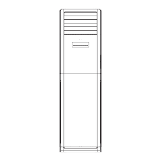
Summary of Contents for Gree GVA60AH-M3NNA5A
- Page 1 S e r v i c e Man u a l MODEL: GVA60AH-M3NNA5A (Refrigerant R410A) GREE ELECTRIC APPLIANCES,INC.OF ZHUHAI...
- Page 4 AUTO HEALTH X-FAN HUMIDITY FILTER TURBO HOUR ON/OFF ON/OFF MODE X-FAN TEMP TIMER TURBO SLEEP LIGHT...
- Page 5 Installing, starting up, and servicing air conditioner can be Make sure the outdoor unit is installed on a stable, level hazardous due to system pressure, electrical components, surface with no accumulation of snow, leaves, or trash and equipment location, etc. beside.
- Page 8 Condition Indoor: DB29 ,WB19 ; Indoor air flow: Super High Pipe length: 5m. Condition Indoor: DB20 ; Indoor air flow: Super High Pipe length: 5m. Outdoor temp.( ) Outdoor temp.(...
- Page 11 GAS SIDE 3-WAY VALVE 4-Way valve Muffler Di s charge HEAT EXCHANGE (EVAPORATOR) Suction Accumlator COMPRESSOR HEAT EXCHANGE (CONDENSER) LIQUID SIDE 2-WAY VALVE i a r t r e n Capillary i a r t r e n COOLING HEATING...
- Page 12 Symbol Parts name Symbol Color symbol Symbol Color symbol OVERLOAD BLUE VIOLET COMP COMPRESSOR YELLOW ORANGE PROTECTIVE EARTH BLACK YEGN CBB65 YELLOW GREEN BROWN CBB61...
- Page 13 POWER YEGN 1YEGN 13BN 14BK 15VT 27BU YEGN OVERLOAD 28YEGN PROTECTOR 21YE 26BU 39VT 23OG 17BU 24WH 12BU 22BK 38BU 19BU 16WH OVERLOAD REVERSAL DEFENSIBLE RELAY PROTECTOR 20BU CONTACTOR 9BK 10VT 11BN (WH) (WH) BN BN COMP (BK) (BK) COMPRESSOR DISCHARGE GAS ROOM TUBE...
- Page 14 Copper insert of live wire Protective tube Copper insert of wire of compressor Control relay of compressor Copper insert of wire of outdoor fan Copper insert of wire of 4-way valve Copper insert of neutral wire Wiring terminal of indoor fan Relay of auxiliary heater Terminals of DISP1 and DISP2...
-
Page 15: Mode Icon
ON/OFF Press it to start or stop operation. MODE Press it to select operation mode (AUTO/COOL/DRY/FAN/HEAT). Press it to decrease temperature setting. Press it to increase temperature setting. Press it to set fan speed. Press it to set swing angle. HEALTH SAVE Press it to turn on or off health function. -
Page 16: Digital Display
Up & down swing icon: is displayed when pressing the up & down swing button. Press this button again to clear the display. Left & right swing icon: is displayed when pressing the left & right swing button.Press this button again to clear the display. SET TIME display: After pressing TIMER button, ON or OFF will blink.This area will show the set time. -
Page 17: Replacement Of Batteries
●In static swing condition, pressing button, the swing angle of left & right louver changes as below: ●If the unit is turned off during swing operation,the louver will stop at present position. X-FAN: Pressing X -FAN button in COOL or DRY mode,the icon "X-FAN" is displayed and the indoor fan will continue operation for 10 minutes in order to dry the indoor unit even though you have turned off the unit. - Page 18 E-HEATER Speed ON/OFF Function AMB. Mode ON/OFF Button ON/OFF Button Under the situation without setting ● Press this button, to turn on the unit. ● buttons, the function, press When unit is turned on, the original setting like Timer, Sleep function will the setting temperature goes up be canceled.Note: When the unit is and down 1...
- Page 19 E-HEATER Function AMB. Speed Mode ON/OFF Speed Buttons (Continued) Speed Button After switch-on at first time, if without ● Press this button, the speed can ● any button input:1. consecutively press shift in the circulation among of twice of buttons in 20 seconds and →...
- Page 20 E-HEATER ON/OFF AMB. Speed Mode Function AMB. AMB. AMB.Buttons (Continued) AMB. Buttons (Continued) The modes of living room, restaurant, ● Under the modes of living room, ● conference/office can only be called restaurant, conference/office,The out by pressing buttons of air con- setting temperature, speed, blowing ditioner panel.
- Page 21 E-HEATER Mode Speed Function AMB. ON/OFF Swing Status of swing Display status of swing. ● Setting Swing Display setting temperature. Status of swing ● Display status of swing. Room temperature ● Indicate temperature of indoor ● BLOW circumstances. BLOW Function Supper strong When the typeface light is on, it ●...
-
Page 22: Running Mode
1. Running Mode 1. cooling; 2. dry; 3. fan; 4: heating; 5. AUTO; 6. others (Freon recovery mode). Temperature Para meter 1. Indoor ambient temperature Tamb. (adopt 15K temperature sensor, external connect 15K partial resistance); 2. Outdoor ambient temperature T (adopt 15K temperature sensor, external connect 15K partial resistance);... - Page 23 ( 3 ) Heating Mode ( this mode is not available for c ooling only un it) 1. Working condition and process for heating When Tamb. Tpreset-1 , the unit will run in heating mode. Meanwhile, compressor and outdoor fan will start running. Indoor fan may be start running after delayed for a period of time to prevent blowing out cold air.
-
Page 24: Other Controls
Freon Recovery Mode That’s the recovery operation method for refrigerant: After the A/C is energized for the first time, set the A/C at FAN mode, low fan speed by remote controller and the indoo r temperature is set as 20 ; Meanwhile, indoor fan will start running. Press the light button on remote controller for twice successively within 5s;... -
Page 25: Protective Measures
When turning on the unit each time, the swing blade must be open to angle 5 (mini position), and then compressor, fan etc. can run. When switching on controller or turning off the unit each time, the swing blade must be at OFF status. 4. - Page 26 2. When compressor is stopped, if it’s detected that the low pressure switch is broken for 30s successively, the complete unit will stop running. Meanwhile, E3 will be displayed and the unit can’t resume running automatically. Only after restarting up the unit and the low pressure switch is resumed, the unit can resume sunning.
- Page 27 1. ON/OFF button Controller is turned on/off by pressing this button. After each pressing of this button, the on/off status will be switched for once. 2. Mode button After pressing this button, it will be selected and displayed as below: Auto cooling heating...
-
Page 28: Display Method
Setting: default to display the setting temperature at ON status, default to display the setting temperature at off status Room temperature: default to display room temperature at on status, default to display to room temperature at off status. (3) After pressing ▲ button and ▼button simultaneously, all buttons on the display panel will be shielded. When pressing any buttons, the buzzer will give out a sound and dual 8 will display “LC”. - Page 29 Blow: when setting blow function, the icon and character will blink; when this function is selected, the icon and character will be displayed. If the blow function hasn’t been selected, the icon and character won’t be displayed. During the time of blow, only the icon and character are displayed, others won’t be displayed.
-
Page 30: Basic Requirements For Installation Location
1. The unit installation work must be done by qualified personnel according to the local rulesand this manual. 2.When removing the unit to the other place, please firstly contact with the local maintenance center. Basic requirements for installation location Installation at the following places may cause failure of the air conditioner. Please contact installation and service agency if the installation at such places cannot be avoided. -
Page 31: Electric Wiring
1.5 meters. Air switch capacity Models GVA60AH-M3NNA5A GVA48AH-M3NNA5B Note: Please pay attention to surrounding conditions (eg. Ambient temp., direct sun shine, rain drops etc.) The data of lead wire cross section listed above is the min. -
Page 32: Notes For Electric Wiring
Notes for electric wiring: Installation diagram, please refer to the following. 1. Special circuit must be used for power supply. For the Signal pahse: 2. The circuit must be installed by special serviceman. Fig.1 3. Please do the wiring according to the following wiringdiagram. The screws Power supply must be tightly fastened, the slippery screws must be changed, the tapping Air switch... - Page 33 30cm Space to the ceiling Air outlet side Space to the wall: (30cm at 10cm least for the pipe side) Space to the rear side Space to the obstruction Air inlet side above Space to the wall above Space to the wall Air outlet side This is just the schematic plan.
-
Page 34: Installation Of Connection Pipe
Installation of connection pipe Drainage Connection pipe pipe Before wiring and piping, please remove the filter after opening the glass panel. Flare-end connection 1.As shown in Fig.2,take out the decorative strip at position 1 and Flare-end connection then unscrew the screws.Remove the screws fixing the filter after Fig.2 Fig.3 opening the glass panel.At last take out the filter along the arro w... - Page 35 5.Place the section with sleeve of the power connection wire into the wire groove, then cover the electric box cover, tighte n the fixing screw,and tighten the connection wire . 6. Recover the electric box cover. 7.For the cooling and heating unit, the signal control wire is connected via connector and indoor unit, and clasp the signal control wire with the wire clamp, which is under the bottom of body case.
-
Page 36: Notes For Piping
Notes for piping Indoor unit Pipes for refrigerant and drainage pipeshould be insulated to avoid frostingand dripping. 1. Both of the indoor and outdoor unitsadopt flare-end connection. Refrigerantpipe as shown below is used to connect indoor and out- door units.(As shown in Fig.8) Bendable pipe Note:Don't bend the bendable pipe back and forth more than 3 times. - Page 37 Installation of connection pipe 1.Align the center of the piping flare with the pyramidal face of relevant valve. 2.Screw in the flare nut by hand and then tighten the nut with spanner and torque wrenc h refer to the following. Indoor unit piping Taper nut Piping Hex nut...
-
Page 38: Leakage Detection
When using vacuum pump 1.Connect charging hose of to charge nozzle. (both cores of gas and Manometer liquid valves should be shut down tightly.) -76cmHg 2.Connect joint of charging hose to vacuum pump. Low-pressure High-pressure 3.Fully open low-pressure valve(Lo) of manometer. valve (Lo) Open valve (Hi) closed 4.Make vacuum pump operate for 15 min above.Close lowpressure... -
Page 39: Wiring Method
Wiring method 1. Remove the front side plate. 2. Put it through to the outdoor wire hole . 3. Please refer to the electric wiring connection of the indoor unit, then fix them with wire clamp.(As shown in Fig.17) Terminal board L1 L2 L3 Rear side plate... - Page 44 Be cautious during installation and maintenance. Do operation following the regulations to avoid electric shock and casualty or even death due to drop from high attitude. Static maintenance is the maintenance during de-energization of the air conditioner. For static maintenance, make sure that the unit is de-energized and the plug is disconnected. dynamic maintenance is the maintenance during energization of the unit.
-
Page 45: Indicator Lamp
Display Method of Indoor Unit Indicator lamp (During blinking, ON for 0.5S Possible Causes A/C Status Error Malfunction Name and OFF for 0.5 S) Code Operation COOL HEAT Lamp Lamp Lamp 1. The main board and the display panel are not connected well. 2. - Page 46 OFF 3S and blinks 3 times 1. The main board and display (inverter panel are not connected well. unit); running 2. The LPP terminal on the main indicator board is not connected well with the blinks high pressure switch on the Low pressure (non-inverter complete unit.
- Page 47 Start Connect the display panel with the main board well Are the display panel and main board Malfunction is eliminated. connected tightly? Are the OVC terminal on the main board connected Connect the OVC terminal on the main board with Malfunction is eliminated.
- Page 48 Start Solve the problem Malfunction is Is there poor air return in the indoor unit? of system. eliminated . Solve the problem Malfunction is Is the fan speed abnormal? of speed. eliminated . Clean the Problem is Is the evaporator dirty ? evaporator solved.
- Page 49 “E3" is displayed on the unit. Is the terminal Re-insert it tightly of low pressure switch to ensure reliable inserted well? contact. Is the malfunction eliminated? Is the system pressure higher than the acting Add refrigerant. value of the low pressure switch? Is the malfunction...
- Page 50 Check the wiring and fan capacitor, replace the motor Check the unit, make the air intake and outlet smooth.
- Page 51 Start Normal fluctuation is within 10% of the rated voltage on the Is the supply voltage unstable with big fluctuation? Malfunction is eliminated. nameplate Is the supply voltage too low with overload? Adjust the supply voltage to maintain it within normal range Malfunction is eliminated.
-
Page 52: Appendix 1: Resistance Table Of Ambient Temperature Sensor For Indoor And Outdoor Units(15K)
Appendix 1: Resistance Table of Ambient Temperature Sensor for Indoor and Outdoor Units(15K) Temp. Resistance kΩ Temp. Resistance kΩ Temp. Resistance kΩ Temp. Resistance kΩ 138.1 18.75 3.848 1.071 128.6 17.93 3.711 1.039 121.6 17.14 3.579 1.009 16.39 3.454 0.98 108.7 15.68 3.333... -
Page 53: Appendix 2: Resistance Table Of Outdoor And Indoor Tube Temperature Sensors(20K)
Appendix 2: Resistance Table of Outdoor and Indoor Tube Temperature Sensors(20K) Temp. Resistance kΩ Temp. Resistance kΩ Temp. Resistance kΩ Temp. Resistance kΩ 181.4 25.01 5.13 1.427 171.4 23.9 4.948 1.386 162.1 22.85 4.773 1.346 153.3 21.85 4.605 1.307 20.9 4.443 1.269 137.2... -
Page 54: Appendix 3: Resistance Table Of Outdoor Discharge Temperature Sensor(50K)
Appendix 3: Resistance Table of Outdoor Discharge Temperature Sensor(50K) Resistance Temp. Temp. Resistance kΩ Temp. Resistance kΩ Temp. Resistance kΩ kΩ 853.5 18.34 4.754 799.8 93.42 17.65 4.609 89.07 16.99 4.469 703.8 84.95 16.36 4.334 660.8 81.05 15.75 4.204 620.8 77.35 15.17 4.079... - Page 55 Steps Procedure Remove air-in panel Remove screws fixing air-in panel and then remove air-in panel. screw air-in panel Remove air-out panel Remove retaining screws on the top and bottom of the air-out panel. Then air-out panel remove air-out panel.
- Page 56 Steps Procedure Remove display panel and step motor Remove retaining screws of controller display panel box and the cover of controller box. Then remove the display panel. Remove screws fixing motor and then remove the step motor. step motor Remove air guard Remove retaining screws of air guard.
- Page 57 Steps Procedure air guard Remove controller box Remove retaining screws of electric box cover and then remove the cover. Unplug each wiring terminal and remove components which need to be removed. Remove retaining screws of electric box and then remove the electric box cover electric box.
- Page 58 Procedure Steps Remove cover plate cover plate Remove screws fixing cover plate and then remove the plate. Remove evaporator Remove retaining screws connecting boards respective on the top and the bottom of evaporator. evaporator Then draw the side plate outwards to remove evaporator, splash plate and water tray.
- Page 59 Procedure Steps Remove propeller housing clamp Remove retaining screws of propeller housing clamp and then draw the clamp outwards to remove it. propeller housing clamp Remove propeller housing Remove retaining screws of propeller housing and then remove the propeller housing. propeller housing...
- Page 60 Steps Procedure Remove centrifugal fan blade Remove nut fixing centrifugal fan blade and then remove the fan blade. centrifugal fan blade Remove motor Remove wire clamp on rear plate and then unplug motor wire. Remove screws fixing motor and then remove motor.
- Page 61 Steps Procedure Remove chassis Remove screws fixing chassis and then remove the chassis. chassis Remove right and left side plates left side plate right side plate Remove screws fixing right and left side plates and then remove the side plates.
- Page 62 Note: Electric heating band is not exemplified in the disassembly below. Steps Procedure 1. Remove the rear grille Remove the tapping screws connecting the rear grille back grille with the back-side plate, the front case and the chassis. Remove the back grille.
- Page 63 Steps Procedure 4. Remove the cabinet Remove the connecting screws fixing the cabinet. Remove the cabinet. cabinet 5. Remove right side plate sub-assembly right side plate Remove the screws fixing the right side plate. Remove the right side plate. 6. Remove electric box sub-assembly Remove the screws fixing the electric box cover.
- Page 64 Steps Procedure 7. Remove axial flow blades axial flow blades Remove the nut on the axial flow blades. Remove the blades. 8. Remove the motors Remove the 4 screws fixing the motors. Disconnect the leading wire inserts of the motors. Remove the motors. motors 9.
- Page 65 Steps Procedure 10. Remove the 4-way valve (Only available for heat pump unit) Remove the nut on the 4-way valve coil and then remove the coil. Wrap the 4-way valve with a wet cloth. Unsolder the 4-way valve quickly and remove it. Ensure that the cloth keeps wet and do not burn the compressor lead.
- Page 66 Steps Procedure 12. Remove the valve Remove the 2 bolts fixing the gas valve. Unsolder the welding joint between the gas valve and the return air pipe. Remove the gas valve. Remove the 2 bolts fixing the liquid valve. Unsolder the welding joint between the liquid valve and the Y-type connecting pipe.
- Page 67 Steps Procedure 14. Remove condenser subassembly Remove the screws connecting the condenser and the chassis. Raise the condenser subassembly to remove it. condenser subassembly 15. Remove valve support subassembly Remove the screw connecting the valve support and the chassis. Remove the valve support subassembly.
-
Page 68: Gree Electric Appliances,Inc.of Zhuhai
GREE ELECTRIC APPLIANCES,INC.OF ZHUHAI Add:Jinji west Rd.Qianshan Zhuhai Guangdong China Tel:86-756-8522219 (After sale Service Dept) Post code 519070...
Need help?
Do you have a question about the GVA60AH-M3NNA5A and is the answer not in the manual?
Questions and answers