Table of Contents
Advertisement
Quick Links
Operating Instructions
3-349-592-02
4/4.12
METRAVOLT 12D+L
Voltage and Continuity Tester
with Phase and Polarity Tester
and Phase Sequence Indicator
GMC-I Messtechnik GmbH
Südwestpark 15
90449 Nürnberg • Germany
Phone +49 911 8602-111
Fax
+49 911 8602-777
E-Mail
info@gossenmetrawatt.com
www.gossenmetrawatt.com
Advertisement
Table of Contents

Related Manuals for Gossen MetraWatt METRAVOLT 12D+L


Summary of Contents for Gossen MetraWatt METRAVOLT 12D+L
- Page 1 Operating Instructions 3-349-592-02 4/4.12 METRAVOLT 12D+L Voltage and Continuity Tester with Phase and Polarity Tester and Phase Sequence Indicator GMC-I Messtechnik GmbH Südwestpark 15 90449 Nürnberg • Germany Phone +49 911 8602-111 +49 911 8602-777 E-Mail info@gossenmetrawatt.com www.gossenmetrawatt.com...
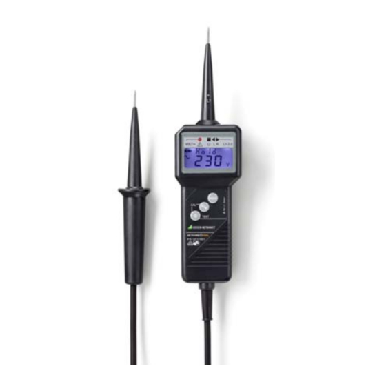
- Page 2 1 Test probes 2 Low voltage display (red LED): as of 50 V AC / 120 V DC 3 LED (green): lights up for resistance measurement from 0 to 1999 k (continuity is indicated by means of a sound generator) 4 LEDs for phase sequence indication left/right 5 Polarity display (~ or –) 6 LCD panel for voltage and resistance...
-
Page 3: Table Of Contents
Rental Instrument Service ....12 Product Support ........12 Applications The METRAVOLT 12D+L is a 2-pole voltage tester with digital display, combined with an integrated continuity, phase and polarity tester, and a phase sequence indicator. It allows for safe detection and... -
Page 4: Safety Precautions
Safety Precautions You have selected an instrument which provides you with a high level of safety. The METRAVOLT 12D+L voltage tester has been manufactured and tested in accordance with requirements set forth in DIN EN 61243-3 (VDE 0682 part 401) regarding 2-pole voltage testers. -
Page 5: Initial Start-Up
Initial Start-Up Battery Your instrument is supplied with an installed 9 V block battery in accordance with IEC 6 LR 61. Attention! Be sure to refer to chapter 6.1 before initial start-up, or after your device has been in storage for a lengthy period of time. Testing for Correct Display and Function According to DIN VDE 0105 part 1, voltage testers must be tested for correct functioning shortly... -
Page 6: Measuring And Testing
Measuring and Testing General Instructions Automatic On/Off The voltage tester is switched on automatically as soon as a voltage value as of 24 V is applied. If “continuity testing” has been activated, the instrument switches automatically to “voltage testing”. The instrument automatically selects the measuring range which corresponds to the applied voltage value (see Characteristic Values). -
Page 7: Voltages Of Less Than 24 V
„–“ appears before the displayed value. Testing of Phase and Phase Sequence The METRAVOLT 12D+L is equipped with two tri- angular LED displays in order to perform phase sequence tests. These tests can be performed at a nominal voltage of at least 165 V (50 Hz) to earth. -
Page 8: Phase Test
4.3.1 Phase Test The phase conductor is determined by applying the test probe (+L1) to the conductor. If “POL” appears at the LCD panel, the conductor is live. 4.3.2 Testing of Phase Sequence The phase sequence between two phases in a grounded 3-phase system is determined as follows by applying both test probes and by clasping the handle bar of the display component:... -
Page 9: Characteristic Values
Characteristic Values Frequency Meas- Measuring Reso- Range / Intrinsic ured Ranges lution Measuring Uncertainty Qty. (auto-ranging) Current 0.10 V 8.99 V 0.01 V (1.5% rdg. 9.0 V 99.9 V U– 0.1 V — + 3 digits) 100 V 1500 V 1.0 V 99.9 V (1.5% rdg. -
Page 10: Maintenance - Recalibration
Electromagnetic Compatibility Interference emission EN 61326:2006 Class B Interference immunity EN 61326:2006 Ambient Conditions Operating temperatures –10 ... + 55 C Relative humidity max. 85% Elevation max. 2000 m Mechanical Design Protection IP 65 Extract from table on the meaning of IP codes IP XY Protection against IP XY... -
Page 11: Housing
The instrument requires one 9 V block battery per IEC 6 LR 61 (alcaline-manganese). Replacing the Battery Ð Loosen the screw at the back of the instrument which secures the battery compartment lid, and remove the lid. Ð Let the battery slide out of the battery compartment with its CAT IV protection cover and replace it. -
Page 12: Device Return And Environmentally Compatible Disposal
Device Return and Environmentally Compatible Disposal The instrument is a category 9 product (monitoring and control instrument) in accordance with ElektroG (German Electrical and Electronic Device Law). This device is not subject to the RoHS directive. We identify our electrical and electronic devices (as of August 2005) in accordance with WEEE 2002/96/EG and ElektroG with the symbol shown to the...
Need help?
Do you have a question about the METRAVOLT 12D+L and is the answer not in the manual?
Questions and answers