Nokia 800Xi Service Manual

18.1” tft-lcd panel colour monitor

Advertisement

Nokia Display Products Oy
P .O.Box 14
FIN ---24101 Salo, Finland
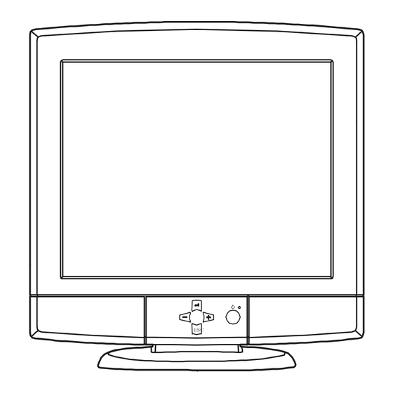
18.1" TFT-LCD PANEL COLOUR MONITOR
800Xi and 800XA and 820L
456A0...
Controller Board.................. SMZ082D
Power/Audio Board.............
456A1...
Controller Board..................
Power/Audio Board.............
Connector Board................. SMT002
456A1...
Controller Board..................
Power/Audio Board.............
Connector Board.................
When re--- ordering manuals, please quote the model name and part number.
Chassis 456A
ESC
1
SMM054D
SMZ090
SMM056
SMZ090
SMM056
SMT002
Contents
Service
Monitor Dismantling
Parts List
PCB Part List
PCB Layout Pictures
Circuit Diagram
ZB1613A
01.00

Advertisement

Table of Contents
loading

Summary of Contents for Nokia 800Xi

  • Page 1 Chassis 456A Nokia Display Products Oy P .O.Box 14 FIN ---24101 Salo, Finland 18.1” TFT-LCD PANEL COLOUR MONITOR 800Xi and 800XA and 820L Contents Service Monitor Dismantling Parts List PCB Part List PCB Layout Pictures Circuit Diagram 456A0... Controller Board....SMZ082D Power/Audio Board.....
  • Page 2 456A...
  • Page 3 Equipment box ZA2559 TCO99 label ZZ2859 Plastic bag ZA0453 Power supply PS0006 Power cord QM0061 Power cord QM0063 Owners CD Nokia 820L/800PRO ZK0034 Installation guide ZF5844 Microfiber cloth XD0050 Padding foamed plastic ZA6032 Microphone cable QM0151 Signal cable QM0312 Label set...
  • Page 4 Part Item Number Description 456A3..
  • Page 5 456A0..
  • Page 6 456A0..
  • Page 7 456A1..
  • Page 8: Table Of Contents

    Service Contents Revision history 1. Important Notes to the User 1.1. Before Installing Your Monitor 1.2. Synchronization 1.3. Image Properties 1.4. Cleaning 2. Product Overview 2.1. Technical Specifications 2.2. Preset Display Modes 2.3. Monitor Connection 2.4. User Controls 2.4.1. Power Switch 3.
  • Page 9: Revision History

    Revision History Rev. Date Prepared by Changed Items 11.98 06.11.98 A. Ahola 05.99 J. Paukku 456A052 added 456A058 added 456A151 added 456A159 added 01.00 27.01.00 J. Paukku 456A351 added 456A359 added 456A...
  • Page 10: Important Notes To The User

    1. Important Notes for the User 1.1. Before Installing Your Monitor Make sure that the monitor is disconnected from the mains supply and the computer is switched off using the power switch Do not place this monitor on an unstable base. Keep the monitor away from heat generating equipment and moist, dusty or unclean places.
  • Page 11: Image Properties

    Do not use water or any other liquid for cleaning. Use a soft, clean and dry cloth (e.g. Nokia Hitec 860003) for cleaning. The use of microfibre cloth is recommended. Dampen the cloth with water or mild detergent if necessary.
  • Page 12 1.5. Audio (Optional in 456A151 and 456A159) 1.5.1. Connectors Audio in 3.5 mm DC in 2xVGA 1.5.2. Amplifier Output power 2 * 1.5 W (RMS) to 16 τ load 1.5.3. Loudspeakers Nominal power 3W Nominal inpedance 16 τ Frequency range 200 Hz --- 18 KHz 1.5.4.
  • Page 13: Product Overview

    2. Product Overview 2.1. Technical Specifications Display ....Active matrix SUPER TFT -- LCD viewable diagonal size 18,1” Stripe Pitch ....Pixel pitch 0.28 (hor) mm x 0.28 (ver) mm Display Surface Treatment Hard coating and anti--clare coating Color Pixel Arrangement...
  • Page 14 Size and Tilt Dimensions Monitor (without stand) ......432.4 mm ......446.9 mm .
  • Page 15: Preset Display Modes

    2.2. Preset Display Modes Right Border Left Border Full 0.7 V intensity Video Blanking H Blanking H Active Video H Back porch H Front Porch H Sync H Sync. Signal Bottom Border Upper Border Full 0.7 V intensity Video Blanking V Blanking V Active Video V Back Porch...
  • Page 16 Right Border Left Border Full 0.7 V intensity Video Blanking H Blanking H Active Video H Back porch H Front Porch H Sync H Sync. Signal Bottom Border Upper Border Full 0.7 V intensity Video Blanking V Blanking V Active Video V Back Porch V Front Porch V Sync...
  • Page 17: Monitor Connection

    2.3. Monitor Connection Make sure that the monitor is disconnected from mains and the power switches of the computer and all attached devices are turned off before connecting the monitor. 1. Connect the signal cable plug to the videocontroller con- nector at the back of the computer.
  • Page 18: User Controls

    2.4. User Controls 2.4.1. Power Switch Push the power switch to turn the monitor on or off When the power is turned on, the power- -on indicator will light. The monitor is turned off with power switch or disconnected from mains outlet if light is out. Input Signal selector Volume...
  • Page 19: Menu

    3. Menu All adjustments and settings are covered with following main menu displays: Brightness, Contrast, Position, Information, All Reset 3.1. Moving in the Menu a) Call the menu to the screen by pushing button. b) Select the header with - -/+ buttons. c) Push to confirm the selection.
  • Page 20: Contrast

    3.5. Contrast Contrast increases the brightness difference between light and dark colors. Adjust contrast adequately according to ambient light conditions to obtain the best picture quality. 3.6. Sub Contrast (R, G, B) With red(R), green(G), and blue(B) intensity controls you may adjust general tint of the picture 3.7.
  • Page 21: Picture Adjustment

    4. Picture Adjustment Start LCDNTEST --program from Nokia Monitor Drivers diskette or use another on/off picture. 1. Select Position / H.Size and adjust vertical disturbances on the screen to minimum. 2. Select Position / Clock Phase and focus the the picture horisontally with the help of text and vertical lines on the white background.
  • Page 22: Display Modes

    5. Display Modes The screen has 1280 horizontally addressable pixels and vertically 1024 pixels. If the incoming signal resolution is 1280 x 1024, the picture fills whole screen. If the resolution of the signal is less than 1280 x 1024, the picture does not fill the whole screen and as a result there may be a black border around the picture.
  • Page 23: Site Preparation

    6. Site Preparation 6.1. Troubleshooting These troubleshooting instructions are meant to eliminate interruptions of use caused by possible easy--to--find defects (e.g. loose connector). Symptom Measures Picture The indi- Check that the power cord is correctly connected to the monitor and to the power screen is cator on unit.
  • Page 24: Workshop Maintenance

    Digital multimeter: Fluke 87 or equivalent true RMS multimeter Signal generator: VTG220 + PC or programmable video generator Color analyzer: e.g. Topcom BM--7 Oscilloscope 40--100 MHz band width ESD protection necessary Nokia Monitor Setup diskette 7.4. Test Patterns Active vertical video time...
  • Page 25: Precautions

    8. Precautions Please pay attention to the following when the TFT--LCD module with the Back--light unit is used, handled and mounted. 8.1. Precautions to Mounting Since the module is thin and heavy, applying strong force to a part of the module may cause partial deformation of frame or mould, and cause malfunctions of the module.
  • Page 26: Precautions To Handling Protection Film

    8.5. Precautions to Handling Protection Film The protection film for polarizer shall be pealed off slowly and carefully by persons who are elec- trically grounded with adequate methods such as list bands. Besides, ionized air shall be blown over during the peeling action. Dusts on the polarizer shall be blown off by an ionized nitrogen gun and so on.
  • Page 27 456A...
  • Page 28: Replacing Lamp Holder Set (Backlight)

    9. Replacing Lamp Holder Set (Backlight) 9.1. Precautions to Replacing Lamp Holder Set During the procedures, all power supplies not only to the module but also to the inverter shall be switched off. Replacing work shall be started after the inverter and backlights become sufficiently cool. Special care shall be taken to the display area in order not to damage its surface The shall not be touched with bare hands to protect its surface from stains.
  • Page 29 Turn the monitor Loosen screws. Turn the monitor Remove the bottom plate Loosen screws and connectors Remove the panel 456A...
  • Page 30 Loosen screws and connector Remove Inverter Loosen screws and connector Remove lamp holder set 456A...
  • Page 31 456A...
  • Page 32: Defect Specifications

    10. Defect Specifications 10.1. Inspection Conditions Room temperature is 25_C ± 5_C Inspect at 20 cm from display Viewing angle and Illumination: Display specifications: --30 ≤ °x ≤ +30, 0 ≤ ∞y ≤ +20 60 lux at a LCD surface Appearance specifications: --45...
  • Page 33: Appearance Specification

    10.3. Appearance Specification Item Specifications Measurement criteria Quality Foreign Materials, Dot shape Average diameter ( ) mm Allowed value St i Stain, Dust ( ) ≤ 0.2 All allowed 0.2 < ( ) < 0.3 ≤ 10 points 0.2 ≤ ( ) ≤ 0.3 ≤...
  • Page 34 456A0.. BLOG DIAGRAM R , G , B G sync TFT COLOR LCD MODULE NL128102AC28- -01A Hs , Cs DCC1/2B VDD VDDB User interface ON / OFF - - select - - up - - down - - reset AC/DC adapter DC/DC 19 V 70 W 12 V 5 A...
  • Page 35 456A...
  • Page 36 456A1.. BLOG DIAGRAM R , G , B G sync TFT COLOR LCD MODULE Hs , Cs NL128102AC28- -01A DCC1/2B Video input selector R , G , B G sync Hs , Cs VDD VDDB Input sel DCC1/2B User interface ON / OFF - -select - -up...
  • Page 37 456A...
  • Page 38 Description Part Part Description Item Number Item Number CN3362 ELCAP 680U M 25V RM5 105ïIMPED QK1497 MINIATURE JACK 3.5MM FOR MIC.OUT CC3580 CHIP CERCAP Y5V 100N Z 50V 0805 QK0923 ROW CONN 1X02 2,5 HOR CB3151 CHIPCERCAP NP0 100P 50V J 0805 AC6100 CHIPRES 1W0 0R02 5% 2512...
  • Page 39 SMM056 SB5231 05.99 Page 2 456A...
  • Page 40 ELECTROLYTIC SMD 1W 3W etc. POLYCARBONATE 0.25W 0.25W NF POLYESTHER POLYPROPYLENE 0.5W 0.5W NF BC857B CERAMIC BC847B 820R VOL1 VOL2 470u 820R 100p 100n VI(1) OUT1+ LEFT OUT OUT1- 100n H8FE-1200 VI(2) OUT2- QK1497 OUT2+ TDA7057AQ 820R n.c. 100p UC7126 0R02 IRF7805 680u...
  • Page 47 Part Description Item Number Number AC4449 CHIPRES 0W1 100R 5% 0805 2013 002 004 005 006 AC4461 CHIPRES 0W1 330R 5% 0805 2013 001 003 CB3121 CHIPCERCAP NP0 6P8 50V D 0805 001 003 004 005 JL0058 LED DUALCOLOR RED/GREEN 3 MM QG0309 PUSH--BUTTON SWITCH 12V 50MA MOM.
  • Page 48 SMZ082D SB5209D 11.98 Page 2 456A...
  • Page 49 Part Description Item Number Number AC4449 CHIPRES 0W1 100R 5% 0805 2013 002 004 005 006 AC4461 CHIPRES 0W1 330R 5% 0805 2013 001 003 CB3121 CHIPCERCAP NP0 6P8 50V D 0805 001 003 004 005 JL0058 LED DUALCOLOR RED/GREEN 3 MM QG0309 PUSH--BUTTON SWITCH 12V 50MA MOM.
  • Page 50 SMZ085 SB5216 11.98 Page 2 456A...

This manual is also suitable for:

820l800xa

Table of Contents